(V) John F. Patterson, Dennis M. Buede, and Robert N. Kraft. (%J ... EDGAR M. JOHNSON ... PERI-POT, 5001 Eisenhower Avenue, Alexandria, Virginia 22333.
Technical Report 628
An Investigation of the Feasibility for Implementing an Advanced Terrain Representation System IC) (V)
John F. Patterson, Dennis M. Buede, and Robert N. Kraft Decisions and Designs, Inc.
(%J 00
I
Nancy B. Mitchell Army Research Institute Battlefileld Information Systems Technical Area Systems Research Laboratory
C3
DTIC (~i~.',)
DEC 031984
E U. S. Army Research Institute for the Behavioral and Social Sciences March 1984 Ap~proved for public release; distribution unlim-te.d
24 -al
20
180
U. S. ARMY RESEARCH INSTITUTE FOR THE BEHAVIORAL AND SOCIAL SCIENCES d
~A Field Operating Agency under the Jurisdiction of thew
Deputy Chief of Staff for Personnel
L. NEALE COSBY Colonel. IN Commiander
EDGAR M. JOHNSON Technical irecctor
Research accomplished under contract to Department of the kirmy Decisions and Detricns, Inc. Technical review by Randall M. Chambers Beatrice J. Farr
NOT ICES OISTRIBUiTION: Please address Army Research
PERI-POT,
Primary distribution of this report has been made by Alil. U.S. correspondence concerning distribution of reports to: ATTN: Sciences, and Social for the Behavioral Institute
5001 Eisenhower Avenue, Alexandria, Virginia 22333.
be dentroyed when Th Is report may FINAL UItPOSITION: Please do not return It to the U.S. ArmyRsac neeed. the Behavioral and Social Sciences. NOTE:
Tre
Vbpartlnent documents.
It
is no longer initefo
findings In this report are not to b~e construed as an officiafl the Army po,.ition, unless so designated by 'ýthet o.uthoriedd
of
%
-4
UNC LASS I FlEDUU SCCURITY CI.ASSIIFICATION
OF THIS PAGE (ti-eRn nlee lIneerd)
REPORT DOCUMENTATION PAGE 1', REPORT NUMBER
I'iechnical 4.
jZ. GOVT
Report
BEFORE COMPLETING FORM ACCESSION NO.
3.
ýLAIYT'-
0~28
RECIPIENT'S CATALOG
NUMBER
______________
S,
TITLE (and Sutbtitle)
TYPE OF REPORT & PERIOD COVERED
Technical Report Period ending October 1982
AN INVESTIGATION OF THE FEASIBILITY FOR IMPLEMENTING AN ADVANCED TERRAIN REPRESENTATION SYSTEM
6. PERFORMING ORG. REPORT NUMBER
DDI/PR 82-10-331 7.
AUTHOR(Q)
S. CONTRACT OR GRANT NUMBER(e)
John F. Patterson, Dennis M. Buede, and Robert N. Kraft (Decisions and Designs, Inc.); Nancy B. Mitchell (ARI) 9.
10. PROGRAM ELEMENT. PROJECT. TASK
PERFORMING ORGANIZATION NAME AND ADDRESS
Decisions and Designs,
Inc.
AREA & WORK UNIT NUMBERS
Suite 600, 8400 Westpark Drive, McLean, VA 22101 II.
MDA903-81-C-0568
P.O.
Box 907
2QI62717A790
CONTROLLING OFFICE NAME AND ADDRESS
14.
REPORT DATE
12.
U.S. Army Research Institute for the Behavioral and Social Sciences 5001 Eisenhower Avenue, Alexandria, VA 22333 MONITORING AGENCY NAME & ADDRESS(If dItsetent from Controlingr
Office)
March 1984 I3. NUMBER OF PAGES
86 IS.
SECURITY CLASS. (of this report)
UNCLASSIFIED IS1.
16.
DISTRIBUTION
STATEMENT (of
DECL ASSI FIC ATI ON/DOWNGRADING SCHEDULE
eths Report)
Approved for public release; distribution unlimited.
17.
IS.
DISTRIBUTION
STATEMENT (of the abesract entered In Block 20, If different from Rp•-,f)
SUPPLEMENTARY NOTES
Contracting officer's representative was Nancy B. Mitchell. A related report is ARI Research Note 84-68, Psychological Research on Advanced Terrain Representation: Formatting the Visual Material. 1I.
,
KEY WORDS (Continue on
efewer#
side If neceseary mid Identity by block number)
Military training Training devices
Videodiscs Terrain Tanks (combat vehicles)
"Simulation 20.
A
'STRACT (Cmutfm
em reiwree
iarwIf nrrec
eary
Surrogate travel Computer-generated imagery Terrain boards
ind Ideniufy by block nu nbet)
Z---7This report describes a feasibility study for- developing a videodiscbased computer system for training small unit armor tactics. This system "will generalize the techniques of-' urrogate travel0•il:.oidez)to provide an advanced terrain representation (ATR) system permitting free travel within a simulated environment. The purpose of ATR is to provide a ground-level perspective of a simulated battle. Using pictures tak-n from many points and perspectives on tlu Lui:ain, the system displays the appropriate pictures in a fashion simulating the movement of the user's tank. *---, (Continued)
DD
FOR
1473
EDITION OF I NOV 65 IS ODSOLETE
.,K
UNCLASSIFIED j
............................
SECURITY CLASStFICATION OF THIS PAGE (Wies" DetS Entfred)
UINCIA,.L. I P1l 1,1, SUCURVtY CLASSIPICATION OF THIS PAGIE(Whe
Dab
8ne.,.d)
ARI Technical Report TR 628 21).
(Cont il.led)
The results of this investiqation indicate that present technology is inadequate to allow for the use of computer-generated imagery (CGI) overlays if the visual base is photographs of real terrain; that a terrain board may be appropriate to CGI use; and that a computer-generated image base, while * lackinq some other desirable properties, provides the greatest certaintj that overlays can be made available. Cr-i,• -or ,-'Li /
Accession For NTIS GRA&i DTIC TAB Unannounced justification
03
By
Distribiition/
AvalniltyCodes i, Dist
Avail and/or Special
af
'
UNCLASSIFIED SECURITY CLASSIFICATION OF THIS PAGEW•Wen Oaf-t •,erod) Si
•"7
7
7
-:."
Technical Report 628
An Investigation of the Feasibility for Implementing an
Advanced Terrain Representation System John F. Patterson, Dennis M. Suede, and Robert N. Kraft Decisions and Designs, Inc. Nancy B. Mitchell
Army Research Institute Submitted by Franklin L. Moses, Chief Information Systems Technical Area
SBattlefield
Approved as technically adequate and submitted for publication by Jerrold M. Levine, Director Systems Research Laboratory
U.S. ARMY RESEARCH INSTITUTE FOR THE BEHAVIORAL AND SOCIAL SCIENCES 6001 Eluenhowat Avenue, Alexandria. Virginia 22333 Offric, Deputy Chief of Staf for Personn-el Deprtment of the Army
MarchJerli. 1984
eie
Army Project Number 20182717A790
Drco
human Performance Effectiveness and Simulation
Aandod for Pumitraen;
unlp
foribuiion
l
tned.
ARI Research Reports and Technical Reports are intended for sponsors of R&O taiks and for other research and military agencies. Any findings ready for implementation at the time of publication are presented in the last part of the Brief. Upon completion of a major phase of the task, formal recon-. mendations for official action normally are conveyed to appropriate military "agenciesby briefing or Disposition Form.
I•
P--
.
..
.
..
FOREWORD 0
The Battlefield Information Systems Technical Area of the Army Research Institute (ARI) has supported the Advanced Terrain Representation (ATR) systems development research presented in this report. The research on the feasibility of implementing the ATR has been done in the interest of producing simulated terrain travel which can be used to enhance both product development and training where navigation over terrain is required.
-
The information presented in this report provides a basis for evaluating the efficacy of producing a terrain travel simulation and offers, in addition, prospects for future considerations as technological development proceeds. Based on this guideline, ARI has proceeded with the development of a terrain travel simulation.
EDGAR M. JOHNSON Technical Director
~.*' ***
*'~.**%
*.% . .
.
%%°
v
*---.-.•
-..
-
AN
INVESTIGATION OF TILE FEASIBILITY
ADVANCED TERRAIN
EXECUTIVE
REPRESENTATION
FOR
IMPLEMENTING
AN
SYSTEM
SUMMARY
Background Battle simulations are important training techniques which have been developed largely for the purpose of tactical and leadership training. Several types of battle simulations, such as CAMMS, Dunn Kemp, and BATTLE, are currently used for training at several levels of command and for somewhat different purposes, but all battle simulations have one or more of the following
characteristics
*
in common.
o
The simulation is manpower intensive, requiring a welltrained controller who derives minimum benefit from the exercise.
o
The information sent by the controller is less than fully realistic because the entire playing surface is not in full view.
o
The simulation cannot be played in
o
The most significant missing element is surprise.
real-time. tactical
This report describes the technical considerations for the development of a battle simulation which would provide a groundlevel view, be played in real-time, incorporate tactical surprise, and eliminate the need for a controller. This prospective simulation is based on a generalization of the "surrogate travel" technology which, by definition, produces an interactive system utilizing a videodisc, a microcomputer, and a CRT. In its current form, it allows the user to control his movement through a display on a CRT in four directions: forward, backward, right, and left. The generalization proposed for the present system would provide an opportunity to travel freely, in more than four directions, over open terrain, in a manner similar to the movement of a tank. The purpose of this particular simulation system is the training of small armored units in tactics, leadership, and land navigation. This report contains the results of "research which was done by Decisions and Designs, Inc. (DDI), "in cooperation with the Army Research Institute (ARI), to determine the feasibility of implementing the simulation now called an Advanced Terrain Representation (ATR).
PRECEDING PAGE BLANK vi-
- --...
-
.- .
.
.
.
",
Method
The production of a videodisc, which is the base for the visual display shown on the CRT, requires pictures that are taken front many grid centers and from many directions of view. These pictures are then displayed in a fashion simulating the -"
movement of the user's If
-. S-tives
the user is
view
o
a simulated area on the order of 2km by 4km;
o
a sense of continuity and travel coherence must be maintained as the user moves from grid center to grid center;
o
the feeling that one is any direction;
o
sufficient detail and texture to support visually guided behavior; and
o
the ability to overlay d~namically changing symbols, such as those of friendly or opposing forces.
free to travel in virtually
In order to achieve these goals, two closely related but distinct information sources are needed, image data and intervisibility data. The image data are generated by the procedures used to create the ground-level pictures for each grid, then placed on the videodisc, and later presented to the user. Intervisibility data refer to information which is extracted, stored, and used to control the overlay of dynamic imagery. The intervisibility data must include information ccncerning the extent to which objects within the full field of view will occlude or obscure an object which is overlayed.
"
'.
I-.
to have any appropriate ground-level
of the terrain and sufficient interactivity and realism to permit him to maneuver his vehicle in the direction called for by the situation represented on the display, then specific objecmust be met. They are as follows:
_
"-.{
tank.
Results The results of this study demonstrate
.
that the development
of an ATR system is feasible and can meet these goals. jor conclusions are: 1.
The tradeoff
between increasing
terrain
The ma-
coverage and
decreasing
the minimum travel speed is
creases
coverage require larger distances between
in
critical.
In-
the grid centers from which the terrain pictures are taken. However, decreases in the minimum travel speed can only be achieved by decreasing these distances
viii
W;W.' • .-'•'''. ,
.
_
.''-
."*r•• ."--'.-*
I..-
-"-'..
.
.'
'
''
""°
"
'""
-
-"
"
"
-''
"
.
.-
,-.
.
" -
" -'""
between
qrid centers.
The minimum time between the
presentation of images to the user is in this tradeoff.
also a factor
2.
In order to achieve an acceptable minimum presentation time, the grid pictures must be allocated to multiple videodiscs in square block patterns. That is, if four videodiscs were used, two videodiscs would store pictures from alternate grids on the odd rows of the grid pattern and the other two videodiscs would cover the even rows in the same fashion. Our recommendation is to use nine videodiscs in a three by three block pattern.
3.
A panoramic (3600) image provides a continuous pivoting (scanning) capability. However it is not achievable at this time if terrain boards are used as the source material for the imagery. In addition, a frame buffer or special effects generator must be included in the system to take advantage of a panoramic image. Therefore, sixteen or twenty-four equally spaced, discreet images should be photographed from each grid and used to simulate pivots. The images should be laid out sequentially on the videodiscs to enable the "step" mode of the videodisc player to be utilized.
4.
The overlay of dynamic symbols (e.g., tanks) on the terrain image requires a range image in registration with the terrain image. The only alternative at this time for creating such a range image is to build an object model of the terrain. The ATR system requirement to achieve this symbolic overlay is a frame buffer with four frames; one each for the terrain image, range image, symbol(s) , and composite image.
Three major uncertainties remain. They can be resolved only by implementing a prototype system and through experimentation: 1.
The responsiveness of the ATR system design to the user's open field travel demands,
2.
The ability of terrain that is computer-generated to provide the needed stimuli for simulating travel, and
3.
The accuracy with which dynamic symbols can be overlayed on noncomputer-generated terrain.
1X
AN INVESTIGATION OF TIlE FEASIBILITY FOR IMPLEMENTING AN ADVANCED TERRAIN REPRESENTATION SYSTEM
CONTENTS Page 1.0
INTRODUCTION .................... 1.1 1.2
2.0
1
Report Organization ............
2
...............
SIMULATING OPEN FIELD TRAVEL ............
.............
2.1
Issues in Videodisc Generat.i.on for ATR ...
2.2
ATR System Parameters ......
2.3
ATR System Parameter Tradeoffs ...
2.4
Videodisc Organization and Use ... 2.4.1 Grid/videodisc patterns ...
2.5
2.6
1
The General Concept of an Advanced Terrain Representation ............... .................
2.4.2
3.0
.....................
6 .....
..............
6 .
11
.........
..
18
......... .........
.. ..
24 25
.
27
Other options for extending coverage
.
.
Simulating Straight Travel, Turns, and Pivots 2.5.1 Straight travel ....... ............. 2.5.2 Turns ........... .................. 2.5.3 Pivots .......... ..................
.
..
31 31 32 33
Hardware Configurations ...... ............. .. 2.6.1 Low cost system configuration ...... .. 2.6.2 System configurations with a frame buffer.
35 36 36
..
TECHNOLOGICAL ISSUES AND SIMULATING INTERVISIBILITY 3.1
3.2
Technological Research Issues .... .......... 3.1.1 Range images ........ ............... 3.1.1.1 Intervisibility calculations 3.1.1.2 Alternatives for achieving range images ... .......... 3.1.2 Terrain boards ...... .............. 3.1.2.1 Terrain boards at Fort Rucker 3.1.2.2 Terrain boards outside the United States .... .......... 3.1.3 Computer-generated imagery ... ........ 3.1.4 Panoramic images ...... ............. 3.1.5 Image rectification ..... ........... Simulating Intervisibility .....
PRECEDING PAGE BLANK
Xi
...........
41 .. ..
41 42 42
.. ..
46 49 49
.. .. .. ..
52 52 53 57
..
59
CONTENTS
(Continued)
Page 4.0
CONCLUSIONS
REFERENCES
AND RECOMMENDATIONS
...........
.....
..
........................
.................
61 65
APPENDIX A ...................
........................
A-I
APPENDIX B ...................
........................
B-I
LIST OF TABLES Table
2-1.
2-2.
Format recommendations based on empirical research .................................. Relationship between number of travel tions and maximum jump ..... ............
2-3.
Minimum presentation
2-4.
System parameters ........
2
.
time
..
10
direc14
(seconds) ........ ...............
Grid size for empirical recommendations maximum jump ........... .................
..
14
..
15
..
19
of
2-6.
Estimates for low cost system configuration
3-1.
Contacts for CGI quality/availability
4-1.
Evaluation of terrain sources ...
.....
.........
38 ..
54
..
64
LIST OF FIGURES Figure 1-1.
Example of ATR grid ...........
2-1a.
4,
2-lb.
24 travel directions ......
8,
.............
and 16 travel directions ...
Plot
of travel
2-3.
Plot
of
frames vs.
grid size
2-4.
Plot
of
frames vs.
coverage
2-5.
Plot of minimum speed vs.
2-6.
Grid allocation
p
vs.
..
12
..
12
..
17
.........
..
21
.........
..
22
.............
2-2.
speed
........
grid
size ... ...
........
grid size
.....
for four videodiscs/players
xii /
.
.
.
.
3
* .. *.".
* * . :
23
26
CONITNTS (Continued) Page
Figure 2-7.
2-8.
Four terrain
images
frame
per videodisc
29
.
Plot of frames vs. grid size (packing four .............. images per frame) .......
30 .
34
2-10.
Low cost system configuration ...................
37
2-11.
System configuration with frame buffer
40
2-9a,b,c.
3-1.
Videodisc sequences for view directions
.
.
.
..
.
Example of overlay size and position determination ........ ................
43
Example of the distinction between the base image and the range image (picture=horizontal white bar in front of vertical black bar on grey field) ........... .................
45
3-3.
Illustration of the computation of occlusion
47
3-4.
Example of encoding scheme for panoramic ................. photography ..........
56
3-2.
3-5.
Example of image
rectification
.
hardware
58
.
m .
xiii
.
.
.
.-..
AN INVESTIGATION OF THE FEASIBILITY FOR IMPLEMENTING AN ADVANCED TERRAIN REPRESEN¶.ATION SYSTEM
1.0
INTRODUCTION
""
One of the major goals of the research presented in this report is the development of a low cost alternative to field training exercises and engagement simulations. The recent development of videodisc-based surrogate travel provides the technological basis for the development of such a battle simulation. Surrogate travel uses photographs that have been stored on a videodisc to provide a realistic simulation of groundlevel travel. Ground-level scenes are photographed at tenfoot intervals along the roads of a town, and then replayed at the request of the rser. The scenes can be sped up, reversed, and stopped. Of even greater significance, choice points (such as right and left turns onto side streets) can be selected, thereby providing a freedom of travel that is unavailable on film or videotape. Although surrogate travel was developed to represent travel through urban streets, the concept can be generalized to represent travel through open terrain. By using this technique of terrain representation, a battle simulation, which presents the player with a ground perspective on the battle, can be implemented. The investigation of the feasibility of developing an Advanced Terrain Representation (ATR) is the subject of this report. 1.1
The General Concept of an Advanced Terrain Representation
The concept of an ATR is the extension of the surrogate travel technology to free travel over opex, terrain. Since a
*
-.
~
S
-
*
•.-."'-'.,
...
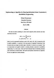
tracked vehicle is not limited to travel over roads, the visual representation of off-road travel is essential to a battle simulation aimed at training the tactics of combined arms. The addition of computer-generated dynamic overlays representing friendly and opposing forces would create a realistic training technique. Figure 1-1 represents one means of segmenting terrain for image capture. Photographs taken from each of these grid centers are represented by the walls surrounding the grid. When these photographs are stored on a videodisc, they can then be displayed on a CRT, and visual travel is produced by moving from grid center to grid center. The variable presentation capability using the random access mode of the videodisc player (as opposed to the deterministic, sequential presentation of film) allows the user to control ie direction of travel; by doing so, the user can respond to a situation by maneuvering in the appropriate direction. The addition of dynamic overlays can create the tactical situation to which users can respond. The objective of this project is the utilization of L-•"is approach to provide a realistic battle simulation for the purpose of training small unit armor tactics.
-'-
1.2
Report Organization
The four sections of this report include the project goals, this section; a summary of the supporting psychological research (Kraft, Patterson, and Mitchell, 1982); a discussion of pivot construction, detailed imagery, and dynamic overlays, Section 3.0; and Conclusions and Recommendations,
-•
Section 4.0.
Goals one through four of the project (large coverage, coherent travel, travel in any direction, and 3600 pivots) are chiefly governed by the pxocedure for acquiring the image data -...
and placing it
on the videodisc.
Travel coherence,
travel
2 i)
*.
.
s-.........'*****
*%.'.%
%
*
IL
Figure 1.-1 EXAMPLE OF ATR GRID
3
freedom, and 3600 pivots are largely a matter of the granularity of the grid and the number of different directions of view photographed for each grid location. In this case, granularity in defined as the distance between grid centers. More pictures will provide the user a richer travel experience, but w.1il result in
less coverage per videodisc.
port to this document (Kraft, et al.,
1982)
The companion reprovides the re-
sults of empirical research on the effects of expanding or relucing granularity relative to these issues. A summary of this research in provided in
Section 2.0.
This section also
contains a definition of the system parameters as well as a discussion of the tradeoffs between these parameters that will define the extent to which these four goals can be achieved. Design alternatives for producing a travel system are also presented in Section 2.0. The last three goals
(3600 pivots, detailed imagery,
and
dynamic overlays) have implications for aspects of the system other than the source to image mapping. Image detail is a matter of the richness of the visual source, regardless of the granularity with which it is filmed. The possibilities for using two sources other than the real world (terrain boards and computer-generated imagery) are discussed in Section 3.0. Dynamic overlays require a particular approach to extracting intervisibility information from the image source. The technological implications for achieving this information are discussed in sented in
Section 3.0 and the system design issues are prea later portion of the same section. Finally, there
are specific technological options available for achieving 3600 pivots, in addition to a large number of discrete views represented by pho~ographs. These options were outlined in the research plan (Patterson, Kraft, and Buede, 1982) and are described in Section 3.0.
4 S. "•
•
.
"--
°
o.*
"
°..
.* *.
.
-
..
.
.
.
s!
°***
.
..
.,.
*w
"\'
Section 4.0 of this report presents our conclusions and recommendations.
5,
""'
v..-
2.0
in
SIMULATING OPEN FIELD TRAVEL
The critical parameters for an ATR system are described this section which also includes a summary of the research
results of Kraft, Patterson, and Mitchell (1982), and a discussion of the major tradeoffs between the various system pa-
rameters. in
A glossary of parameter abbreviations can be found
Section 2.3.
The section is
concluded with a discussion of
the details of the ATR travel concept, videodisc organization, travel components, and hardware requirements. 2.1
Issues in Videodisc Generation for ATR As part of the ATR research,
(Kraft,
Patterson,
an empirical investigation
and Mitchell,
1982) was conducted to help
design a videodisc-based system for Advanced Terrain Representation (ATR). Ideally, the system would present a complete and veridical representation of a natural tactical environment. However, because of the storage constraints inherent in videodisc technology, the amount of information which can be presented is limited. Psychological research was conducted to help define the boatds for a compelling, pedogogically effective system within the storage constraints. The research was designed to examine tactically motivated perceptual issues related to the format of the visual material. The primary issue was concern with the most efficient way to represent a large piece of terrain in a perceptually coherent and tactically informative fashion. The purpose of this research was to establish the bounds of perceptual acceptability for use in subsequent technological development.
guiding
Angle of View, Jump Distance, Number of Viewing, and Travel Directions were format variables examined empirically
*
6 *
S.........'...........
.
..
¥
...
~
*
,{
*-***.-4.**
'
'
because they represent the basic building blocks for constructing a videodisc-based representation of open-field terrain. Angle of View refers to the angular size of the photograph used to create the visual display for the system and is directly related to the focal length of the camera lens. Angle of View typically ranges from 300 and below (telephoto) to 450 ("normal") up to 900 (wide angle) and beyond. The wider the angle, the greater the amount of information contained in the photograph, and the more the objects in the pho-
-.
tograph appear to be stretched out.
-
Jump Distance refers to the maximum jump size that can be allowed between grid centers, and Number of Viewing Directions and Number of Travel Directions are both determined by the number of photographs taken from each grid center.
The proper parameters for each of these format variables was determined by four experiments which are summarized balow. In Experiment 1 distance perception was examined as a function of viewing angle. Findings showed that distance perception along the depth plane was significantly affected by viewing angle; the wider the angle, the greater the perceived distance. A viewing angle of 900 appears to be the widest distortionfree angle, closely approximating distance perception in the real world. The results of Experiment 1 also demonstrated that the perceived distance between any two objects depicted
•-2
in the scene was unaffected by viewing angle. The perception of hills was examined in Experiment 2. The results demonstrated that viewing angle significantly affected steepness perception, and further, that visual travel over terrain interacted with perceived steepness. A 900 viewing angle created no more distortion or variability than any of the other viewing angles being tested. This experiment 7 ..
. ...
-
also replicated the major finding of the first experiment, i.e., widening the Angle of View increases estimates of distance. In addition, Experiment 2 results demonstrated that height perception can be affected by viewing angle: when viewers were visually on a hill, viewing angle significantly affected height perception; when the hill -as viewed from a distance, perceived height remained constant across the different viewing angles. The two format variables of concern in Experiment 3 were: Jump Distance and Number of Viewing Directions in two types of terrain. In lightly wooded terrain, visual travel remained coherent up to Jump Distances of 20m, but began to fall apart at 30m. At a Jump Distances of 40m, travel coherence was unacceptably poor. These results suggested that the maximum allowable jump size for lightly wooded terrain should be 25m. Pivots remained coherent with successive angular displacements of 150, but become increasingly incoherent with displacement of 22.50 and 300. These results suggested that the maximum allowable angular displacement in lightly wooded terrain should be 151 and thus, 24 viewing directions would be needed to specify a complete 3600 pivot. In open terrain, visual travel remained coherent up to Jump Distances of 35m. At 55m, travel coherency broke down, but at 75m, a high degree of travel coherence returned. It appears that the greater the Jump Distances, the greater the likelihood that a significant landmark will disappear between successive views or that the general terrain characteristics will change from from one view to the next. It was still possible to maintain coherent linear travel with a Jump Distance of 75m, given a highly homogeneous stretch of terrain. Since a potential loss of coherence can occur at 75m, however, the maximum allowable Jump Distance in open terrain should be set at 50m. Pivot coherence in open terrain was consistently high
.•.
V• 'y-
".
'V•E'
•~g
~• t
÷'•
.;÷÷•..•.
'•$
,
*'•:.v
..
.
.
.- ... .
.
..
-..
.
..
o
.
.
.
across all the levels of angular displacement that were tested. A 300 angular displacement was as coherent as a 7.5° angular
Thus, the maximum allowable angular displacedisplacement. ment in open terrain should be set at 300, indicating that 12 viewing directions would be needed to specify a complete 3600 pivot. The objective of Experiment 4 was the determination of the Minimum Number of Travel Directions needed to provide the ATR user with a sense of free travel. Subjects viewed film sequences representing linear travel along a path which was oblique to the desired direction of travel. The results suggest that for a 900 viewing angle, subjects will become uneasy about going astray when the angular discrepancy between the desired and actual direction of travel is approximately 150, indicating an upper limit of 24 travel directions. Subjects will experience a strong need to correct their travel path when the angular discrepancy reaches approximately 22.50, indicating a lower limit of 16 travel directions. These results apply to both lightly wooded and open terrain. For a more complete description of this research, see Kraft, Patterson, and Mitchell, 1982. It should be noted that a nonempirical investigation was conducted concerning image resolution. The results of this investigation indicate that a resolution of 256 x 256 pixels would provide sufficient detail and texture to support visually guided behavior for the ATR visual display. Table 2-1 summarizes the empirical findings for formatting the ATR videodisc imagery.
9
~~..-.
•
FORMAT VARIABLE
PARAMETER VALUE 900
VIEWING ANGLE
MAXIMUM ALLOWABLE JUMP DISTANCE
S-
Lightly Wooded Terrain
25m
Open Terrain
50m
MINIMUM NUMBER OF VIEWS -
Lightly Wooded Terrain
24
-
Open Terrain
12
MINIMUM NUMBER OF TRAVEL DIRECTIONS
16 or 24
Table 2-1 FORMAT RECOMMENDATIONS BASED ON EMPIRICAL RESEARCH 10...
*.
10"""
.5'.°
j,.
5
2.2
ATR System Parameters The foundation of the ATR system is
the terrain imagery
which will be captured from the center of each grid that has been laid upon the terrain. The baseline assumptions for the ATR system are as follows: (1)
The terrain grid will consist of homogeneous squares.
(2)
One terrain image (a given view direction from a given grid) will be stored on one videodisc frame.
(3)
Only the "random
access" and "step" modes of the
videodisc player will be used.
Random access of the
videodisc frames takes one to three seconds for cur-
"rent optical videodisc systems, and this mode will be used for moving the user from one grid to another. The "step" mode can access adjacent videodisc frames in one tenth of a second or more
(as controlled by
-
the system) and will be used to present adjacent view directions to the user.
"This system assumes the minimum availability of specific hardware
(see Table 2-6 and Figure 2-10).
signs are presented in
More sophisticated de-
Section 2.6.
The number of directions of travel permitted within the grid, Number of Travel Directions
(d),
and the maximum jump
distance permitted within the grid, Maximum Jump (j), are intimately related. Figure 2-la depicts four travel directions (two perpendicular streets) and eight travel directions
(every
450) in the upper left corner. The case for sixteen travel directions is shown in the middle of Figure 2-la and for twenty-four directions is
depicted in
Figure 2-lb.
Both of
11.°.
............................ .
...
...
1000'
ccN
OD=
122
these cases were defined to achieve equal angular displacements between travel directions. In each case, the Maximum Jump,
j,
is
labeled.
Table 2-2 shows the Maximum Jump dis-
tance in terms of g for each of the examplary travel directions depicted in Figures 2-la, b. The last column is the range of j's. In every situation, the minimum jump is corresponding to a north/south or east/west translation. The Minimum Presentation Time
(t)
is
g,
a function of the
ATR system's ability to access the videodisc file in
antici-
pation of the grid to which the user's travel direction and speed are likely to take him. function of hardware
The system's access time is
a
(e.g., the use of a frame buffer or not)
and the number of non-redundant parallel videodiscs and players. These system features will be discussed in Sections 2.4, 2.5, and 2.6, but Table 2-3 presents our best estimate of t
(in seconds) as a function of frame buffer capability and number of parallel videodiscs. (Note that a frame buffer will be required to refresh the terrain image if there is only one videodisc and player.) Maximum Presentation Time mined by user acceptability. year,
T
(T),
Table 2-4,
must be deter-
Based upon pilot tests this
may increase for very slow speeds (0-5 mph)
there will be little
change over time.
It
since
may also be pos-
sible to use a frame buffer or special effects generator with continuous zoom capability to simulate travel during the presentation of a single t. rain image.
Although zoom and travel
are not the same ?erceptually, for a period of one to two seconds they may be similar enough to convey travel and extend T. Additional discussion of this hardware option will be presented later in
Section 2.0.
Minimum Speed (s)
is
the Maximum Jump
imum Presentation Time (T):
s = j/T.
(j) divid..
Since
j
is
Max-
a function
13
.... ... .... ... ,*
*.--*-**. ,.-.~*%~.-
*'-*.*--.-*%.'*-.
*
**.*,~...'*..
**-..
,*.*o---
-C.
Travel Directions-
d
16 24
j
Maximum a~~~~ 1.4 Jump-j g
.0-..4Range
2.16 g 3.46 g
1.41 2.82
-
2.16 g 3.46 g
Table 2-2 RELATIONSHIP BETWEEN NUMBER OF TRAVEL DIRECTIONS AND MAXIMUM JUMP
Number of Videodiscs/Pl~ayers
Frame Buffer No
Yes 1•0
1-
S1.0
9 16 25
0.5 0.33 0.25
0.33 0.25 0.20
Table 2-3 MINIMUM PRESflUTATION TIME (SECONDS) (Based upon a one-second random access search by the videodisc player)
14
. . .-.-.-.....-.-...-..
.
.
.
..
"...
Definitions
Symbol
System Parameter Grid Size
g
distance between grid centers (meters)
Coverage
c
area of terrain covered 3) by the grid (knm
Number of Travel Directions
d
number of directions of travel permitted within the grid maximum jump distance permitted within the grid (meters)
Maximum Jump
Minimum Presentation Time
t
minimum time for presentation of terrain imagery (seconds)
Maximum Presentation Time
T
maximum time for presentation of terrain imagery (seconds)
Minimum, Speed
s
minimum travel speed (greater than 0) permitted by the system (mph)
Maximum Speed
S
maximum travel speed permitted by the system
7,
(mph)
Number of View Directions
v
number of directions of viewing from a given grid location
Videodisc Frames
f
number of videodisc frames available for storage of terrain imagery
Table 2-4 SYSTEM PARAMETERS
15
-m
e
:4.e
of the particular travel direction chosen within each of the s also cases of 8, 16, 24 Travel Directions (Table 2-2), For planning purposes s should be detervaries with d. T can If mined by the largest j in the range of each d. s can be decreased. be increased beyond one second,
-
Maximum Speed (S) is the smallest jump in the range of IMaximum Jumps for a liven Number of Travel Directions (d) (as shown in Table 2-2) divided by t, Minimum Presentation Time. Figure 2-2 presents the ranges of Maximum Speed (S) and Minimum Speed (a) as a function of Grid Size for d equal to
.
p
eight. The Number of View Directions (v) is an independent parameter that directly impacts coverage. However, in order to preserve coherent travel, there should be a view direction for each travel direction so the traveler can look in the direcThis means that d is a lower limit for tion being traveled. V.
*
There are approximately 54,000 frames on one side of a Thus Videodisc Frames (f) equals 54,000, 216,000, videodisc. 486,000, 864,000, and 1,350,000 for 1, 4, 9, 16 and 25 nonThe reason for concenredundant videodiscs, respectively. trating on 1, 4, 9, 16, and 25 is to decrease Minimum Presentation Time, which will be explained in more detail in section -
2.4. (c) equals the Number of Videodisc Frames (f) times the area covered by one grid element (ga), divided by f92 the Number of View Directions per grid (v)j then, c V cvv . f Or for a given coverage Coverage
16
00
dw CV)
N........
1712
2.3
ATR System Parameter Tradeoffs
In order to produce a reasonable dispersion between Minimum and Maximum Travel Speeds (a and S), there must be a dispersion between Minimum and Maximum Presentation Times (t and T) :
b.o.
t
S.
T where j = the Maximum Jump.
I
Referring back to Table 2-3 and our pilot studies which indicate that T should not be greater than one second, our conclusion is that a significant number of non-redundant videodiscs and players are needed to achieve a spread between T and t. See Table 2-4 for a glossary of terms. Figure 2-2 shows the ranges of Maximum and Minimum Speeds, as a function of Grid Size (g), for the case of 8 Travel Directions. The ranges for S and s result from the ranges of Maximum Jump, depending upon the particular travel direction. The point of this figure is the high values for Minimum Speeds (s) when Grid Size (g) is greater than 10m. The range of Maximum Speeds (S) when Grid Size (g) equals 10m falls well within the reasonable limits for tank travel. Increasing the Number of Travel Directions to 16 and 24 as recommended empirically, exacerbates these problems because Maximum Jump increases even more. Table 2-5 presents the relationship between g and the empirical recommendations for J, as a function of Number of Travel Directions (d). In conclusion, g
18 "I,
,
, ,
""
, ,
,
,
,
,
,
Number of Travel Directions
d
8
Maximum Jump Recommendations
Lightly Wooded:
open:
25m
50m
16
17.7m
11.6m
7.2m
35.5m
23.2m
14.5m
Table 2-5 GRID SIZE FOR EMPIRICAL RECOMMENDATION~S OF MAXIMUM JUMP
19
24
must be between 7 and 12m for lightly wooded terrain and 14-23m for open terrain. The empirical research suggests that at least 16 and probably 24 view directions are needed to convey a continuity of scanning and traveling to the user. It is this variable together with Coverage (c) and Grid Size (g) that determine the number of Videodisc Frames
(f)
needed.
Figure 2-3 shows when Coverage is set at
the relationship between f and g our original goal of 8km2 (2 x 4) and Number of View Directions (v) is set at 16 and 24. This figure suggests that g must be kept above 17-20m to achieve nine or fewer videodiscs. Figure 2-4 plots f versus c for cases of g = 10, 15, 20 and 30m and v set at 16. This figure also demonstrates the need to keep g above 15m to achieve reasonable coverage with nine or less videodiscs. One of the major issues that must be resolved during system development is the tradeoff between the need to increase Coverage and to decrease Minimum Speed, factors which pull Grid Size in different directions.
I
Figure 2-5 shows that Grid
Size (g) must be in the 5-10 meter range in order to achieve a Minimum Travel Speed (s) of 10-20 mph for 16 or 24 directions of view. One method for achieving such a tradeoff is the use of the concept of heterogeneous or adaptive grids.
This con-
cept would allow grid size to decrease when moving from open to lightly wooded terrain and would provide small grids for precise positioning and slow speeds. However, the use of such
*
a concept would also introduce additional complexity into the system if smooth travel from one grid center to the next were to be maintained. Even with the use of an adaptive grid concept, the size of a grid would need to average approximately 15m in order to confine the system to a reasonable number of videodiscs. A
20
.t
. -
. *-t
f
,
,
,.
I*•~.
** -*i
.i*. ie~*