i cell is fully represented by a MoM impedance matrix ii. Z , a current vector i. I (modal currents vector) and a voltage vector i. V having dimension respectively. 2.
AN ITERATIVE INTEGRAL EQUATION METHOD TO MODEL LARGE COMPLEX ARRAYS Mauro Bandinelli, Rodolfo Guidi Electromagnetic Lab. of IDS, Ingegneria Dei Sistemi, Via Livornese 1019 56010 Pisa, Italy Abstract. Accurate modelling of arrays is required in order to perform design activities and excitation law synthesis. Specially care must be devoted to the mutual coupling among cells which, if not properly controlled, can lead to wrong designs and also can give undesirable effects such as the well known “scan blindness” one. This paper presents a Moment Method based Iterative Technique suitable to model large and complex planar arrays compounded of geometrically and electrically complex cells, without any regularity property of the grid. The same approach has already been applied by the authors also to the different, but similar in some relevant basic features, problem of the modelling of HF antenna farms, Bandinelli et al. [5].
PRELIMINARY STATEMENTS Purpose. The accurate modelling of large arrays, compounded of complex multiports cells, is mainly needed in the frame of design activities. Both Y/Z/S−parameters and embedded patterns are required to perform array optimisation. That means to look for a base of the solution space, called in the following “canonical” solution. It is worth noting that any “active” solution can be obtained by means of a simple linear combination of the components of the canonical solution. Preliminary statements. The proposed approach is based on some preliminary statements, reported in the following: the cells of the array are not electrically connected; a MPIE (Mixed Potential Integral Equation) based Method of Moment procedure is used to model the cells; it is well known that a MoM approach for the whole array is usually impracticable; nevertheless it is desirable for the accuracy usually requested in design activities. Scenario and symbolism. Let’s consider a planar array composed of N c not−connected elements (cells). N p ports can be located on each cell. Voltage generators and loads can be located on each port. The array will be modelled by means of a numerical method based on a Method of Moment approach. From the electromagnetic point of view the generic i th cell is fully represented by a MoM impedance matrix Z ii , a current vector I i (modal currents vector) and a voltage vector Vi having dimension respectively N 2 , N and N . The following symbols will be adopted, again using bold letters for vectors and matrices: Vi0 : excitation vector of the i th cell due to locally defined unit voltage generators; I i0 : modal currents induced on the i th cell due to Vi0 (initial step of the iterative procedure); Z ij : MoM impedance matrix between cells “ i ” and “ j ”; Zij I j represents the (voltage) perturbation induced by cell “ j ” on cell “ i ”; s : s th step of the iterative procedure (s = 1, N s ) ; I i(s ) : modal currents induced on the i th cell at the s th step of the iterative procedure ; ∆(js −1) I i( s ) : perturbation induced on the i th cell at the s th step of the iterative procedure, by the current distributed on cell “ j ”, evaluated at the (s − 1)th step. SYNCHRONOUS ITERATIVE METHOD In order to overcome the well known problems of a simple first order perturbative method an iterative technique is proposed. Such technique allows to take into account both the direct and the feedback interactions between each couple of cells, as long as the induced perturbation falls under a user selected threshold . From a mathematical point of view the approach is in someway similar to some previously proposed iterative procedures for the solution of classical Method of Moments problems, applied to single large scatterers, Ferguson et al. [2], Baldwin et al. [3], Fourie et al. [4]. Let us consider the situation where a unit voltage generator Vn0 = 1 is located at the port of the n th cell, as required for the evaluation of the array canonical solution (only one port for cell is supposed in order to simplify the notation). At step “0” the currents induced on each cell by local generators are evaluated by considering each cell working in isolation. It is worth noting that I i0 = 0 for cells where no generator is defined. I i0 = Z ii −1 V i0 , i = 1, N c
URSI EMTS 2004
(1)
555
At step “1” the current on the i th cell is updated considering the perturbation induced on it by the currents evaluated all over the other cells at step “0” (i.e. the currents due to generators located on the cells themselves): I i(1) = Z ii− 1 Vi0 −
Nc
Z ij I 0j = Z ii− 1 Vi0 −
j = i, j ≠ i
Nc
Z ij Z jj − 1V j0
i = 1, N c
(2)
j = 1, j ≠ i
∆(j0) I i(1) = Z ii−1 Z ij I 0j represents the ∆−current induced on the i th cell by I 0j . It is worth noting that ∆0j I i(1) = 0
when no generator is defined on cell “ j ”. This is exactly the situation we have to handle in the evaluation of the array Y/Z/S−parameters. Stopping the procedure at this step only the direct interaction between couples of cells is considered, while the presence of the other ones is neglected. This is the minimum step needed to evaluate an array canonical solution (i.e. S/Y/Z− parameters). At the generic step “ s ” the current on the i th cell I i(s ) is in general evaluated as: I i( s ) = Z ii− 1 Vi0 −
Nc
Z ij I (j s − 1) , i = 1,N c
(3)
j = 1, j ≠ i
It is worth noting that in general: SIM takes into account in a “synchronous way” the perturbations induced on each cell at each step; SIM allows for the reaction of a cell on itself, through a multiple scattering mechanism by the other cells; SIM allows for a cascade−mechanism where a perturbation induced on the cell “ k ” reacts on the cell “ i ” through cell “ j ”. The procedure above described, drawing attention to the “physical point of view” is a particular application of the iterative Jacobi method for the solution of linear systems, applied on a block−matrix basis, Bini et al. [1]. In our case, each cell of the array represents a block of the overall array MoM matrix. A different procedure, referred to the Gauss−Seidel method, has been devised and applied. That procedure requires the same number of multiplication for iteration as Jacobi but at the same step “s” it allows to take into account a larger number of interactions among cells and therefore it is expected to be more accurate and faster than Jacobi. On the contrary it doesn’t allow equal accuracy on each cell at the same step “s”, that is it is not a “synchronous” procedure, in the sense that the cells are not all simultaneously updated at each new iteration. NUMERICAL EXAMPLES An example of application of the SIM method, relevant to a patch array, is reported in order to show its applicability and performance, by referring to a full−wave MoM modelling of the entire array. The “medium size” periodic rectangular array sketched in Fig. 1 has been modelled in order to evaluate S−parameters as a function of the frequency, in the range [1100,1300] MHz.
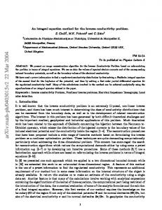
Fig. 1 - 32 elements rectangular array layout
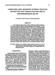
The array is composed of 32 square patches located on a 4 x 8 square grid having ∆x=∆y=16,9 cm (centre to centre distance). Each patch is fed through two vertical pins located at the centre of two consecutive edges. 378 basis functions have been used to model each patch, so requiring 12096 unknowns for the MOM modelling of the entire array. Fig. 2 shows amplitude and phase of some Sij coefficients vs. frequency. SIM (Jacobi) and Gauss−Seidel results relevant to “error threshold =0.1%” are compared with those obtained by means of a classic MoM model of the entire array. The runs have been performed on a Unix 677 MHz Alpha Server DS20E, having 2 Gbyte RAM. Data relevant to the RAM required to the storing of the interaction
556
URSI EMTS 2004
matrices and CPU time relevant to a single frequency analysis are reported in Tab.1.
Fig. 2 - S-parameters(module and phase) vs. frequency, for SIM, Gauss-Seidel and classic MOM.
Classic MoM for the entire array SIM (Jacobi) Gauss−Seidel SIM (Jacobi) Gauss−Seidel
RAM (Mbyte) ∼1116 58 58 58 58
CPU time Error threshold (s) 12867 / 1843 0.1 1619 0.1 1170 1 1180 1
=0.1%
(%)
Tab. 1 - Computation requirements for iterative methods and classical MOM procedure
The results of the iterative procedures relevant to =0.1% are practically indistinguishable from the MoM ones, both for strong (S1,1, S1,2) and weak (S1,64) coupling, and have been obtained using about 5% of RAM and in about 13% of the time. A further on better performance in terms of reduced CPU time is clearly obtainable by relaxing the “error threshold” requirement. For example about the same accuracy is retained using =1%, while the CPU time is reduced to only 9% of the time needed for a standard MoM application. CONCLUSIONS An iterative procedure is proposed, suitable to solve large and complex planar arrays, by taking into account for the mutual coupling among cells and so allowing accurate design activities and excitation law synthesis. The method is based on a MPIE − MoM representation of the cells and on iterative numerical schemes suitable to be applied on block−divided structures, as many arrays are. The sub−sectional MoM applied to the single cell allows good accuracy and versatility. The iterative schemes allow to take into account mutual coupling effects with substantially the same accuracy levels, without the prohibitive computational resources requested by a full MoM application on the entire array. The procedure doesn’t base itself on any theoretical strong hypothesis, so allowing a large field of application and some interesting features for real life array configurations. REFERENCES [1] Bini D., M. Capovani, O. Menchi, “Metodi Numerici per l’Algebra Lineare”, Edit. Zanichelli 1993. [2] Ferguson T.T., T.H. Lehman, R. J. Balestri, “Efficient solution of large moments problems: theory and small problem results”, IEEE Trans. On AP, Vol. AP−24, March 1976. [3] Baldwin P.J., A. Boswell, D. Brewster, J. Allright, “Iterative calculation of ship−borne HF antenna performance”, IEE Proceedings-H, Vol. 138, April 1991. [4] Fourie A.P.C, D.C. Nitch, A.R. Clark, “A sparse iterative method (SIM) for Method of Moments calculation”, Aces Journal, Vol. 14, No. 1, March 1999. [5] Bandinelli M., F. Marsich, G.M. Sammarone, “An efficient performance analysis procedure for HF ground stations design”, International Wroclaw Symposium And Exhibition On Electromagnetic Compatibility - Wroclaw, Poland, 25−28 June 2002.
URSI EMTS 2004
557