are PCR (peak cell rate), MBS (maximum burst size) and. SCR (sustainable cell rate) ... control algorithm that produces a VBR stream which rate varies between ...
AN MPEG2-TO-ATM CONVERTER TO OPTIMIZE PERFORMANCE OF VBR VIDEO BROADCAST OVER ATM NETWORKS Paul C.M. Wong, Victor C.M. Leung and Panos Nasiopoulos Department of Electrical and Computer Engineering The University of British Columbia Vancouver, B.C., Canada, V6T 1Z4 {paulw, vleung, panosn} @ece.ubc.ca ABSTRACT This paper presents a novel MPEG2-to-ATM converter for VBR video broadcast over ATM networks. It functions as an external post-coding source rate controller between any MPEG2 source and an ATM network. Dynamic break points are employed to shape and partition the video data into high priority ATM cells which conform to the prevailing usage parameter control contract with the network, and nonconforming low priority cells which minimize the effects of cell loss due to network congestion on the subjective quality of the received video. Both high and low priority cells are transmitted over a common ATM virtual connection. Performance evaluations of actual VBR MPEG2 streams transmitted over a simulated converter and ATM network are presented to demonstrate the effectiveness of the proposed method.
1. INTRODUCTION Whereas variable bit-rate (VBR) MPEG2 video is desirable for broadcasting applications due to bandwidth savings, the resulting traffic characteristics are content-dependent and highly unpredictable [1]. Before broadcasting video over an ATM network, a service contract is established specifying the source traffic descriptors and the required quality of service (QoS). Usage parameter control (UPC) or policing is performed at the network access point to ensure conformance of the source traffic to its descriptors, using such algorithm as the leaky bucket. This protects the network from misuse of resources by misbehaving sources, which can affect the QoS of other connections. For realtime (rt-) VBR traffic, the key traffic descriptors for UPC are PCR (peak cell rate), MBS (maximum burst size) and SCR (sustainable cell rate) [2]. ATM cells conforming to the UPC parameters are guaranteed delivery with the specified QoS, while nonconforming cells may be dropped by the network when congestion occurs. As cell losses
result in degradations of the received video quality, careful management of the video stream transmission is necessary to minimize their effects on received video quality relative to human visual perception [3]. One of the major extensions of MPEG2 video over MPEG1 is the addition of scalability, which can support applications with multiple-layers of video. One such application involves the provision of several different levels of video quality to accommodate various classes of users. A two-layered source coding scheme generates a base layer which contains the basic video information. This base layer can be solely decoded to provide a basic video quality. The residual information is coded as an enhancement layer so that when received and added to the base layer, enhanced video quality can be obtained. A priority scheme similar to the idea of "data partitioning” (DP) as described in the MPEG2 video compression standard [4] to have multiple layer outputs have been used [5, 6, 7] to produce multiple layer outputs. Furthermore, the use of a hierarchical encoding scheme and a dynamic DP strategy is proposed to generate multiple layers of MPEG2 video streams [8]. However, multiple layer encoding requires processing at the source, and multiple transmission channels with different QoS are usually assumed for the different layers. For ATM networking, this could mean sending the basic layer using rt-VBR, and the enhancement layer using the available bit rate (ABR) service. Synchronization issues arise at the receiver where the multiple layer streams from the respective ATM virtual connections need to be combined for decoding. Another common approach is to control the VBR video bit-stream transmitted by the source so that it conforms to the specified UPC contract and buffer constraints, while keeping picture quality degradations within acceptable levels. This approach is known as source rate control [5, 6] and also employs DP at the source. In earlier work [9, 10, 11], DP was based on splitting the DCT coefficients at some predetermined point resulting in two partitions of the bit-streams, but in recent works, adaptive DP algorithms have been proposed. Luo
and El Zarki [6] designed an adaptive DP scheme within the MPEG framework, which has the capability of detecting long bursts, and react accordingly to stay within the ATM contract requirements. Hamdi, Roberts and Rolin [12] presented a rate control algorithm that adjusts the coder quantization parameter on a group of pictures (GOP) basis to ensure that the output satisfies the burstiness constraint imposed by leaky-bucket policing. Reibman and Haskell [13] presented bit-rate constraints that prevent codec buffer overflow in the case of a leaky-bucketcontrolled channel. Heeke [14] and Coelho [15] proposed to make the encoder output behave like a predefined Markov chain. Pickering and Arnold [16] proposed a rate control algorithm that produces a VBR stream which rate varies between predefined upper and lower bounds. Pancha and El Zarki [17] also proposed a similar rate control algorithm as [13] but using a bucket that is a few frames long to control traffic variability. However, source rate control at the encoder is not always practical or desirable, e.g., in the cases of preencoded video archive, or video traffic originating from another network that has no notion of UPC. In this paper, we propose a novel MPEG2-to-ATM converter, which functions as an external post-coding source rate controller between any MPEG2 source (archives, live programs, etc.) and an ATM network. Dynamic break points (BPs) are employed to shape and partition the video data into high priority ATM cells which conform to the UPC contract, and low priority ATM cells which are subject to network congestion induced losses. The partitioning aims to minimize the effects of cell loss on the subjective quality of the received video. Several video streams are used for the MPEG2-to-ATM converter evaluations. Performance evaluations by simulations have shown that by reducing the number video frames received with low peak signal-tonoise ratio (PSNR), our converter improves both the overall PSNR and subjective quality.
2. MPEG2 VIDEO MPEG2 is a generic method for compressed representation of digital video sequences using a common coding syntax [4] defined by the International Organization for Standardization (ISO) and the International Electrotechnical Commission (IEC). In MPEG2, there are 4 profiles defining the colorspace resolution and scalability of the bit-stream. The levels define the maximum and minimum for image resolution and Y (Luminance) samples per second, the number of video and audio layers supported for scalable profiles, and the maximum bit rate per profile [18]. The combination of a profile and a level produces an
architecture that defines the ability of a decoder to handle a particular bit-stream. The Main Profile meets the needs of 95% of the users [18]. In this paper, MPEG2 Main Profile streams are used. The MPEG2 video standard defines a hierarchy of data structures in the video stream. It has six layers: sequence layer, GOP layer, picture layer, slice layer, macroblock layer, and block layer. A video sequence begins with a sequence header and may include additional sequence headers, contains one or more GOPs, and ends with an end-of-sequence code. A GOP includes a header and a sequence of pictures. A picture is the primary coding unit of a video sequence. Generally, there are three types of pictures in MPEG2 video, namely, the intra-frames (I frames), the predicted frames (P frames) and the bi-directional frames (B frames). An I frame marks the start of a certain coding period and is obtained by simply encoding an individual picture by spatial compression without utilizing any related information in the past or future frames. An I frame is always the starting frame of a GOP intended to allow random access. A P frame contains temporally compressed information predicted from a previous I- or P-frame. A Bframe is generated by considering the contents in both the immediate past and future I- or P-frames. The sequence of pictures in a GOP therefore has a pattern similar to: I B B P B B P B B P I B B P …, etc. In the above example, the GOP size is 10 frames. A block is an 8-pixel by 8-line set of values of a luminance or a chrominance component. A macroblock is a 16-pixel by 16-line section of luminance components and the corresponding 8-pixel by 8-line section of the two chrominance components. A slice is one or more contiguous macroblocks. Slices are the basic unit for error handling. If the bit-stream contains an error, the decoder can skip to the start of the next slice. 2.1
MPEG2 Data Partition
In order to reduce high spatial redundancy in both image blocks and prediction-error blocks, the MPEG2 algorithm transforms 8x8 blocks of pixels or 8x8 blocks of error terms from the spatial domain to the frequency domain using the Discrete Cosine Transform (DCT). Then, the encoder chooses a quantization matrix that determines how each frequency coefficient in the 8 X 8 block is quantized. The combination of DCT and quantization results in many of the frequency coefficients being zeros, especially the coefficients for high spatial frequencies. To take maximum advantage of this, the coefficients are organized in a zigzag order to produce long runs of zeros. The coefficients are then converted to a series of run-amplitude pairs, each pair indicating a number of zero coefficients and the amplitude of a non-zero coefficient. These runamplitude pairs are then coded with a variable-length code,
which uses shorter codes for commonly occurring pairs and longer codes for less common pairs. Future Frames Info.
Similar to JPEG's frequency progressive mode, only the slice layer indicates the priority break point (PBP), which is the maximum number of block transform coefficients contained in the particular bit-stream. The DP method may be employed to break the block of 64 quantized transform coefficients in the frequency domain into two bit-streams. The first, higher priority bit-stream contains the more critical lower frequency coefficients and side information (such as DC values and motion vectors). The second, lower priority bit-stream carries higher frequency AC data. According to the MPEG2 compression standard, the PBP information is stored in the slice headers.
Current Level Info.
Traffic Manager
Current Frame Info.
Token Generating Rate = SCR
Token Pool Max. Level = MBS PBP Assignment
Token Pool
MPEG2 -> AAL5 -> ATM Converter
ATM Cells
1st Buffer MPEG2 STREAM
MPEG2 ES Buffer
TO ATM NETWORK
2nd Buffer PCR
For SCR & MBS Requirements
For PCR Requirement
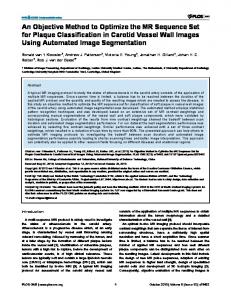
Figure 1: Structure of MPEG2-to-ATM Converter
3. MPEG2-TO-ATM CONVERTER The role of the MPEG2-to-ATM converter is to serve as a video data processor and protocol formatter between the MPEG2 video source and the user-network interface (UNI) that connects the source to an ATM network. At the source, the MPEG2-to-ATM converter functions as an external post-coding source rate controller positioned between any MPEG2 source (archives, live programs, etc., which may be remotely located) and the UNI. It accepts MPEG2 video data and outputs ATM cells with two priority levels such that high priority (HP) cells always conform to the UPC contract policed by the UNI, and low priority (LP) cells may be non-conforming and are marked in the cell-loss priority (CLP) bit in the cell header as candidates for discarding by the ATM network. ATM cell transmissions employ one virtual connection for both priority levels, for which a service contract is assumed to have been pre-established in our subsequent performance evaluation. An ATM-to-MPEG2 converter at the receiver performs the reverse operation of assembling an MPEG2 stream from the received HP and LP ATM cells for playback. The proposed converter is targeted for both real-time and non-real-time broadcasting applications. Consequently, it is assumed that a delay of the video stream in the converter for up to 2 s can be tolerated. The service UPC contract includes three parameters: MBS, SCR and PCR for rt-VBR traffic. Using a concept similar to the PBP, DP using a dynamic BP is applied to the DCT coefficients in the incoming stream of VBR MPEG2 video data to yield a HP and a LP bit-stream, containing respectively, low and high frequency coefficients. According to the MPEG2 video standard, PBPs can be defined only on a slice-by-slice basis. However, the MPEG2-to-ATM Converter controls the source rate by changing the BP continually.
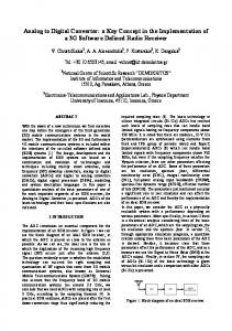
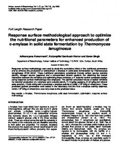
Figure 1 shows the structure of the converter. The incoming bit-stream (up to 60 frames or 2 s) is stored in the elementary stream (ES) buffer, and examined by the Traffic Manager (TM) to determine the traffic load of current and future frames. Combining this information with the available resources (tokens) from a simulated leaky bucket model, the TM then assigns a proper distribution between HP and LP ATM cells by determining an appropriate BP. The DCT coefficients in the incoming VBR MPEG2 bit-stream is separated into HP and LP data according to the BP, converted into ATM Adapter Layer 5 (AAL5) Protocol Data Units (PDUs) and subsequently into HP and LP ATM cells for transmissions over the ATM network. Figure 2 shows the flow chart of the overall operations of the MPEG2-to-ATM converter. 3.1 Data Structures In the ATM adaptation layer, AAL5 is selected by the ATM Forum to produce PDUs from MPEG2 transport packets [19]. Since there are two different priorities of data, two data structures are developed for HP and LP MPEG2 data. The overhead of the HP data structure, shown in Figure 3, is minimized in order to minimize the overall overhead introduced by the entire data structure. An end of block (EOB) code word is used to separate each piece of information, which is considered as the basic information unit in the data structure. In the following, the term “piece” refers to this basic unit. Pieces may contain either header information, or coefficient data information. For example, the first piece of the sequence contains the sequence header, GOP header, slice header, and coefficients, followed by the first EOB. The next piece generally contains only coefficient data. The BP in this scheme defines the number of encoded nonzero coefficients to be included in the HP AAL5 PDU. All
headers, motion vectors and the first DCT coefficient (i.e., the DC coefficient) are always placed in the HP PDU without exception followed by the encoded DCT coefficients in each block up to the BP. HP data is accumulated until the length is over 376 bytes. This number is chosen because an MPEG2 Transport Stream (TS) has a fixed size of 188 bytes, and the default length for the MPEG2 AAL5 PDU is 2 TS packets [18]. This accumulated data then becomes the data payload in a HP AAL5 PDU, and is padded with extra bytes if needed to ensure that the PDU length is a multiple of 48 bytes, the payload size of an ATM cell.
Therefore, the LP data structure has more overhead information than that of HP data. A section of a MPEG2 Elementary Stream: E E E HP LP O HP LP O HP O HP LP B B B
E O B
Low Priority Data
EOB:
HP Data: HP B1 Flag
End of Block
Bn: B2
B3
B4
Bn-1
Block with index n A block includes data & EOB
Bn
1 Bit (Priority Indicator) MPEG2 compliant
The length is about 376 bytes
Begin: Encounter Sequence Header
Pads Reserve
HP Data HP AAL5 PDU:
Encounter a GOP header
A
E E HP: HP LP O HP O High Priority Data B B LP:
Length
0 - 47 16 bits 16 bits bytes Size is multiple of 48 bytes
CRC32 32 bits Segmented into High Priority ATM cells
Figure 3: Data Structure for High Priority Data Update Token Pool Level
Calculate the standard ratio for current GOP
Re-evaluate the BP setting
Based on the future traffic load & current bandwidth resources
From BP Look Up Table, find the corresponding BP setting
The LP data structure is shown in Figure 4. The first bit indicates that the current AAL5 PDU is an LP one. The block reference (B_ref) indicates which HP block the following LP data block is associated with. The next two fields are block size (B_size) and block data (B_data). LP data are likewise padded so that the PDU length is a multiple of 48 bytes.
N End of GOP? Video Data Process
Y Update BP Look Up Table
Assign HP data to HP AAL5 PDU data field. Assign LP data to HP AAL5 PDU data field.
Send out the HP AAL5 as HP ATM cells & LP AAL5 (if there is one)
Pad with pad bytes, reserve bits, length of data, CRC32 bits to form AAL5 PDU format
Y End
E E HP LP O HP O B B
LP B_ B_ B_ B_ B_ B_ Flag Ref1 Size1 Data1 Ref2 Size2 Data2
Y Encounter End of Sequence ?
E E E E HP LP O HP LP O HP O HP LP O B B B B
HP: High Priority Data LP: Low Priority Data EOB: End of Block B_Refn: Block reference (used to match HP block)
LP Data: Is a HP AAL5 PDU ready?
N N
A section of a MPEG2 Elementary Stream:
A
B_ B_ B_ RefK SizeK DataK
1 Bit (Priority Indicator) The length is much less than 376 bytes
LP Data LP AAL5 PDU:
Pads Reserve
K is the index of the last block with LP data.
Length
0 - 47 16 bits 16 bits bytes Size is multiple of 48 bytes
CRC32 32 bits Segmented into Low Priority ATM cells
Figure 2: Flow Chart of MPEG2-to-ATM Converter
Figure 4: Data Structure for Low Priority Data
Simulation results show that about 22.8% overhead is introduced by this data structure; however, 99.8% of this is contributed by the overhead of the AAL5 PDU and ATM cell. LP data pieces containing frequency coefficients beyond the BP are packed into LP AAL5 PDUs, which are not considered as bandwidth consuming, because the CLP bits in these ATM cells are marked for possible discarding by the network. The LP AAL5 PDU must provide enough information for the receiver to assemble the received LP data with the HP data into an MPEG2 compatible stream.
Both HP and LP AAL5 PDUs are segmented into ATM cells for transmission. The HP AAL5 PDU is sent out first, followed by the LP AAL5 PDU, if any. At the receiver, an ATM-to-MPEG2 converter is responsible for converting these ATM cells back to the original MPEG2 stream by properly merging the HP and LP data, using the information given by the EOB, B_ref, and B_size. 3.2 Break Point Assignment Algorithm The BP assignment algorithm employs the same DP
concept as the PBP in the MPEG2 video standard, by separating the 64 DCT coefficients of each block into low frequency HP coefficients and high frequency LP coefficients. However, whereas the MPEG2 video standard fixes the PBP for each slice, in our MPEG2-to-ATM converter, the BP is varied dynamically for each AAL5 PDU. Its implementation adds almost no extra overhead (only about 0.2 % of the total overhead). The next task is to determine proper BP values.
PDU may vary during the GOP period. The Standard_ratio needs to be adjusted at the end of the GOP if its current value results in token pool overflow or underflow during the next GOP. The adjusted Standard_ratio is given by ratio of number of tokens available during the next GOP (No. of tokens generated in the GOP – MBS + current token pool level) and the number of tokens required to transmit all video data during the GOP.
The BP value is determined by the TM for each AAL5 PDU, based on comparing the future bandwidth demand of the MPEG2 video data (up to 60 frames or 2 s) stored in the ES buffer with the future bandwidth available, as determined from a simulated UPC process using a leaky bucket model. In this model, tokens are generated into a leaky bucket at a rate given by the SCR, and each ATM cells must acquire a token for it to be transmitted as a conforming cell, with CLP bit unmarked. Unconsumed tokens are held in the bucket or token pool, until it overflows and the excess tokens are lost. The size of the token pool is given by the MBS. The available future bandwidth is a function of the current token pool level in the simulated leaky bucket, and the token generation rate. ATM cells which fail to acquire a token are transmitted with the CLP bit set so that they are candidates to be dropped by the network when congestion occurs.
The next step is to make sure that the PCR requirement is also met. If the average cell rate for the next GOP (GOP1_CR) is larger than PCR, the Standard_ratio might need an adjustment. If the Standard_ratio is greater than PCR/GOP1_CR, then Standard_ratio is set to PCR/GOP1_CR in order to meet the PCR requirement.
In the BP assignment algorithm, a key variable called the Standard_ratio is used to prevent the token pool from running out of tokens and thus provide smooth traffic shaping. Suppose analysis of the ES buffer by the TM reveals that at time T within the next 2 s, the token pool will be at its lower level. The current Standard_ratio is defined as the ratio between the number to tokens available up to time T and the total number of token needed if all the video data were to be transmitted as conforming cells. For example, suppose the calculated Standard_ratio is 0.6, and the current HP and LP PDUs contain 12 and 17 ATM cells, respectively (the larger number in the LP PDU is due to the overhead introduced by the LP data structure). If all the video data is to be transmitted without DP, there should be 12/0.6 = 20 ATM cells in this time period. In this case UPC allows only 12 HP ATM cells to pass during this time period when the source data is equivalent to 20 ATM cells. Note also that our DP scheme actually results in a larger total number of HP and LP cells to be transmitted, due to a larger number of LP cells. In order to get the best picture quality while maximizing the video data throughput, the distribution of HP and LP data must not change abruptly, and the token pool level should be close to zero at time T. The Standard_ratio is fixed during a GOP period and recalculated for the next GOP, but the BP setting for each
Once the Standard_ratio is determined, the BPs are set for each HP AAL PDU. The BPs are assigned such that the resulting number of HP ATM cells follows the calculated Standard_ratio. First, the BP values are assigned using a BP lookup table. A default BP lookup table is included in the converter, but it can also be user defined. The BP lookup table is updated as the video stream passes through in order to reflect the current MPEG2 video traffic characteristic. Since there are no absolute BP values corresponding to a certain Standard_ratio, BP settings are updated continually during the GOP period to follow the Standard_ratio as follows. Once a HP AAL5 PDU is ready to be sent, the BP settings are evaluated for the next PDU by calculating the Real_ratio for the previous PDU, which is defined as the ratio between the number of HP ATM cells sent and the total number of ATM cells required by all the video data before DP. Basically, if the Real_ratio is within +/- 1% of the calculated Standard_ratio, the BP values are unchanged. However, if there is more than a +/- 1% difference, the BPs are increased or reduced as appropriate. At any instance, if the token pool level drops to a predefined level called Min_token_pool_level (e.g., 10 tokens), the BP settings will be set to a pre-defined minimum level for I, B and P frames to prevent the token pool from running out of tokens. These pre-defined levels can be user defined also. Therefore, the token pool level would be slightly above zero when the worst case occurs, reducing video quality degradation to a minimum.
4. PERFORMANCE EVALUATION The performance of a number of VBR MPEG2 video streams has been evaluated. The traffic diagrams of two such streams are shown in Figs. 5 and 6.
ATM Cell Rate (cells per 1/15 second)
300 250 200
Stream #1
150
SCR
100 50 1
21
41
61
81
101
121
GOP No.
Figure 5: Data Rate Profile for Stream #1 ATM Cell Rate (ATM cells per 1/15 second)
values for the shaped traffic are less than or equal to these setting values because reducing one parameter effectively also reduces the other source traffic parameters. For example, Table 3 shows the effective values for these three parameters of two test cases with stream #1.
300 250
Test No.
SCR
PCR
MBS
1
171
244
26832 (90%)
2
171
250
23850 (80%)
3
171
250
20869 (70%)
4
171
250
17888 (60%)
5
171
250
14907 (50%)
6
162 (95%)
250
29813
7
154 (90%)
250
29813
8
145 (85%)
250
29813
9
137 (80%)
250
29813
10
128 (75%)
250
29813
200
Stream #2 150
SCR
100 50 1
21
41
61
81
101
GOP No.
Figure 6: Data Rate Profile for Stream #2
Table 2: Testing cases for Stream #1 Each stream is first analyzed by a computer routine to calculate the ATM traffic parameters required to pass 100% of the video data by setting I frame BP (Ibp), P frame BP (Pbp) and B frame BP (Bbp) to 64 (this is known as the 646464 case). Then the 484848 case (by setting Ibp = Pbp = Bbp = 48) is used as a starting point for performance evaluation. The ATM traffic parameters requirements for these cases are listed in Table 1.
Stream No.
646464
484848
SCR
PCR
MBS
SCR
PCR
MBS
1
187
279
31091
171
244
29813
2
160
279
23281
149
244
28593
Table 1: Contract Parameter Requirements for Stream #1 and Stream #2 (SCR and PCR in no. of ATM cells per 1/15 s; MBS in no. of ATM cells) By using the ATM traffic parameters of the 484848 case as a starting point, 10 different test cases are developed with more restrictive UPC parameters. In the first 5 cases, MBS setting varies from 90% down to 50%. In the last 5 cases, the SCR setting varies from 95% down to 75%. The test cases for stream #1 are shown in Table 2. Note that the SCR, PCR and MBS are the ATM UPC contract parameters and also the parameters used by the simulated leaky bucket model. The effective (or real)
Test No. Converter 1.1 UnControlled 1.1 FixedControlled 1.1 Converter 1.5 UnControlled 1.5 FixedControlled 1.5
SCR (effective) 171 (171)
PCR (effective) 249 (250)
MBS (effective) 26828 (26832)
147 (171)
250 (250)
26832 (26832)
164 (171)
244 (250)
26832 (26832)
165 (171) 117 (171)
249 (250) 250 (250)
14904 (14907) 14907 (14907)
143 (171)
244 (250)
14907 (14907)
Table 3: Example of real UPC parameters vs. setting UPC parameters For each case, three methods to transmit the data through the ATM network are compared. Method one does not employ any control for partitioning the video stream based on the content. The incoming VBR MPEG2 bit-stream, with the PBPs of the I, P, and B frames all
equal to 64, is simply converted into ATM cells which are passed through UPC policing for transmission over the ATM network. There is no processing to separate video coefficients into different priority levels. All ATM cells violating the service contract are dropped. This is referred as the "uncontrolled" case. Video headers can be discarded as well, and the loss of these headers renders the subsequent video coefficients useless and could result in significant received signal quality degradation. The second method employs "fixed control" to partition the DCT coefficients at some predetermined PBP to eliminate the LP coefficients. An example of this case is 484848, where the PBPs for I, P and B frames are 48, 48 and 48 respectively. All the headers and HP coefficients are sent in ATM cells through UPC policing to the ATM network. Non-conforming cells are dropped by the ATM network. This is based on the argument that only the more important coefficients should be sent to save bandwidth and achieve smooth video quality degradation. However, the fixed PBP does not guarantee UPC conformance for the resulting HP coefficients, and therefore suffers from the same problem of degraded received video quality due to video header losses, as in the uncontrolled case. The third method uses our MPEG2-to-ATM converter to partition the video data using dynamically assigned BPs. LP cells are dropped by the network. It automatically ensures that cells carrying headers and HP coefficients conform to the UPC contract and pass through the network intact.
PSNR (in dB)
45 40
Converter
35
Uncontrolled Fixed-Controlled
30 25 0
3
6
9
Test No.
Figure 7: Average PSNR for Stream #1
PSNR (in dB)
50 45 Converter
40
Uncontrolled
35
Fixed-Controlled
30 25 0
3
6
9
Test No.
Figure 8: Average PSNR for Stream #2
Test No. 1.1
Converter
UnControlled 38.45 dB 41.6 dB (100%) (85.6%) 1.2 38.35 dB 40.54 dB (100%) (83.9%) 1.3 38.14 dB 38.66 dB (100%) (80.0%) 1.4 37.74 dB 37.15 dB (100%) (76.4%) 1.5 37.46 dB 35.12 dB (100%) (70.9%) 1.6 37.45 dB 36.06 dB (100%) (71.9%) 1.7 35.51 dB 33.26 dB (100%) (63.7%) 1.8 34.11 dB 31.51 dB (100%) (57.6%) 1.9 33.10 dB 30.17 dB (100%) (52.0%) 1.10 32.02 dB 29.05 dB (100%) (55.1%) PSNR for the 484848 case is 40.40 dB
Fixed Controlled 38.78 dB (95.5%) 37.88 dB (93.1%) 37.14 dB (91.3%) 36.5 dB (89.8%) 35.45 dB (86.5%) 35.2 dB (75.7%) 32.11 dB (60.9%) 30.26 dB (50.7%) 29.18 dB (43.3%) 28.11 dB (59.6%)
Table 4: Average PSNR and channel efficiency for Stream #1 Test No. 2.1
Converter
UnControlled 49.53 40.09 (100%) (76.2%) 2.2 45.93 39.58 (100%) (75.2%) 2.3 44.49 38.53 (100%) (73.1%) 2.4 43.25 37.35 (100%) (70.0%) 2.5 42.03 35.48 (100%) (62.8%) 2.6 44.87 38.9 (100%) (74.6%) 2.7 41.75 36.98 (100%) (71.7%) 2.8 39.51 35.37 (100%) (67.4%) 2.9 37.75 33.47 (100%) (62.3%) 2.10 36.41 31.82 (100%) (55.1%) 484848 case is 39.92 dB
Fixed Controlled 38.19 (93.5%) 36.63 (88.2%) 35.37 (83.3%) 34.97 (81.9%) 33.23 (73.4%) 35.05 (82.5%) 32.88 (73.6%) 32.04 (70.3%) 30.94 (65%) 29.87 (59.6%)
Table 5: Average PSNR and channel efficiency for Stream #2
No. of Frames
For stream #2, the converter has the best average PSNR performance (Fig. 8 and Table 5). However, that is not always the case for stream #1 (Fig. 7 and Table 4). Furthermore, it was observed that the average PSNR does not match the results of subjective evaluations of the received video playback through a hardware MPEG2 decoder. Therefore, we introduce another method to evaluate the picture quality, which, instead of the average PSNR, uses a frame by frame PSNR comparison. The PSNR values are calculated for individual frames. From subjective tests, it was found that the 242424 case still gives a good picture quality while the 161616 case gives only a marginally acceptable picture quality. Therefore, the frame-based PSNR of 242424 and 161616 cases are used as references for comparison between the three methods. 600 400 200 0 0
3
6
9
Test No. Converter 0%
13%
13%
3%
3%
1.2
0%
0%
14%
14%
5%
5%
1.3
0%
0%
17%
17%
6%
6%
1.4
1%
0%
20%
19%
8%
8%
1.5
2%
0%
24%
23%
11%
10%
1.6
0%
0%
24%
24%
13%
12%
1.7
1%
0%
31%
31%
24%
24%
1.8
11% 0%
36%
36%
31%
31%
1.9
21% 0%
41%
41%
36%
36%
1.10
36% 0%
46%
45%
42%
41%
Table 6: Percentage of Number of Frames below 242424 PSNR and 161616 PSNR Lines for Stream #1 Figs. 9-12 and Tables 6-9 show that the MPEG2-toATM converter gives the least number of frames which PSNRs are lower than those of the corresponding frames in the 242424 case (i.e., below the 242424 PSNR line) and no frames below the 161616, while both uncontrolled and fixed-controlled methods have most of the low PSNR frames under the 161616 line. This is in agreement with subjective evaluations, which show that the converter produces the best picture quality, while the other two methods give substantially lower subjective picture quality.
0
No. of Frames
Figure 9: No. of Frames Below 242424 PSNR Line for Stream #1
500 400 300 200 100 0 0
3
6
9
Test No . for Stream #2 Converter
Un-Controlled
500 400 300 200 100 0 3
Fixed-Controlled
6
9
Test No. for Stream #2 Converter
Un-Controlled
Fixed-Controlled
Figure 11: No. of Frames Below 242424 PSNR Line for Stream #2 No. of frames
Uncontrolled
Fixed-Controlled
0%
Test No. for Stream #1 Converter
Uncontrolled
1.1
No. of Frames
In each case, after converting the received ATM cells into an MPEG2 stream, the average PSNRs for the entire video sequence and each individual frame are calculated. The data for average PSNR are shown in Figs. 7 and 8 and tabulated in Tables 4 and 5, which also show the corresponding channel efficiency at the receiver. The receiver channel efficiency is defined as 1-(X/Y) where X = no. of received cells discarded by receiver due to missing video headers; Y = total no. of cells received reflects the number of ATM cells that are wasted due to the loss of the corresponding video headers.
600 400 200 0 0
3
6
9
Test No. for Stream #1
Fixed-Controlled
Converter
Un-Controlled
Fixed Controlled
Figure 10: No. of Frames Below 161616 PSNR Line for Stream #1
Figure 12: No. Of Frames Below 161616 PSNR Line for Stream #2
Test No.
Converter
Uncontrolled Fixed-Controlled
2.1
0%
0%
20%
21%
4%
4%
2.2
0%
0%
21%
21%
9%
9%
2.3
0%
0%
23%
23%
13%
12%
2.4
0%
0%
25%
25%
14%
14%
2.5
0%
0%
31%
31%
21%
21%
2.6
3%
0%
22%
22%
14%
14%
2.7
12%
0%
25%
25%
22%
22%
2.8
18%
0%
29%
28%
25%
25%
2.9
31%
0%
34%
34%
30%
30%
2.10
42%
0%
40%
40%
35%
35%
Table 7: Percentage of Number of Frames below 242424 PSNR and 161616 PSNR Lines for Stream #2
4. CONCLUSIONS We have presented a novel method for post-encoding source rate control of VBR MPEG2 video data to conform to ATM UPC policies at the network interface. From the simulation results, it is apparent that our MPEG2-to-ATM converter significantly improves the picture quality of video by maintaining a high PSNR for the majority of received frames. Because frames with very low PSNR have a much greater effect in degrading the subjective quality of the received video, the MPEG2-to-ATM converter gives the best performance in terms of subjective quality, as confirmed by subjective evaluations. Furthermore, our designed data structure introduces almost zero overhead, and the converter is applicable with any MPEG2 source without the need of changing the coding method at the source or using multiple ATM virtual connections for multi-layer transmissions.
ACKNOWLEDGEMENT This research was supported by a grant from the Canadian Institute for Telecommunications Research under the NCE program of the Government of Canada.
REFERENCES [1] J. Ni, T. Yang and D. H. K. Tsang, "CBR Transportation of VBR MPEG2 Video Traffic for Video-On-Demand in ATM Networks", Proc. ICC/SUPERCOMM'96, Vol.3 , pp1391-1395, June 1996.
[2] ATM Forum, "Traffic Management Specification Version 4.0”, ATMF95-0013R10, 1995. [3] W. Luo and M. El Zarki, "Quality Control for VBR Video over ATM Network”, IEEE J. on Sel. Areas in Commun., Vol. 15, pp. 1029-1039, Aug. 1997. [4] Generic Coding of Moving Picture and Associated Audio, ISO/IEC 13818-2, MPEG2 Draft International Standard, May 1994. [5] M. R. Ismall, I. E. Lambadaris, M. Devetsikiotis and A. R. Kaye, "Modeling Prioritized MPEG Video Using TES and a Frame Spreading Strategy for Transmission in ATM Networks”, Proc. IEEE INFOCOM’95, pp. 762-770, 1995. [6] W. Luo and M. El Zarki, "Adaptive Data Partitioning For MPEG2 Video Transmission Over ATM Based Networks”, Proc. IEEE International Conference on Image Processing, pp.17-20, 1996. [7] W. Luo and M. El Zarki, "Quality Control for VBR Video over ATM Networks”, IEEE J. on Sel. Areas in Commun., Vol. 15, pp. 1029-1039, August 1997. [8] P. Cuenca, L. Orozco-Barbosa, L. Wang, A. Garrido and F. Quiles, ”An Error Concealment Scheme for MPEG2 Video Transmission Over ATM-Based Networks”, Proc. IEEE CCECE’97, 1997. [9] R. J. Siracusa, K. Joseph, J. Zdepski and D. Raychaudhuri, "Flexible and Robust Packet Transport for Digital HDTV”, IEEE J. on Sel. Areas in Commun., Vol. 11, pp. 88-98, Jan. 1993. [10] M. Ghanbari, "Two-Layer Coding of Video Signals for VBR Networks”, IEEE J. on Sel. Areas in Commun., Vol. 7, Jun. 1989. [11] P. Pancha and M. El Zarki, "Prioritized Transmission of VBR MPEG Video”, Proc. IEEE GLOBECOM’92, pp.1135-1139, 1992. [12] M. Hamdi, J. W. Roberts, and P. Rolin, "Rate Control for VBR Video Coders in Broad-Band Networks”, IEEE J. on Sel. Areas in Commun., vol. 15, pp.10401051, August 1997. [13] A. R. Reibman and B.G. Haskell, "Constraints on variable bit rate video for ATM networks,” IEEE Trans. Circuits Syst. Video Technol., vol. 2, pp. 361372, Dec. 1992. [14] H. Heeke, "Traffic control algorithm for ATM networks,” IEEE Trans Circuits Syst. Video Technol., Vol. 3, pp.182-189, June 1993. [15] R. Coelho and S. Tohme, "Video coding mechanism to predict video traffic in ATM network,” Proc. IEEE
GLOBECOM’93, pp.447-451, 1993. [16] M. R. Pickering and J. F. Arnold, "A perceptually efficient VBR rate control algorithm,” IEEE Trans. Image Processing, vol. 3, pp.527-532, Sept. 1994 [17] P. Pancha and M. El Zarki, "Leaky bucket access control for VBR MPEG video,” Proc. IEEE INFOCOM’95, Boston, MA, Apr. 1995. [18] P. Nasiopoulos, "A course on DVD Authoring", UBC Graduate Course material, 1997 [19] S. Varma, "MPEG2 over ATM: System Design Issues”, Proc. IEEE COMPCON’96 pp. 26-31, 1996.
Paul Wong was born on May 19, 1971. He received his B.A.Sc. (Hons.) degree from the Department of Electrical and Computer Engineering, University of Waterloo, Ontario, Canada in 1995. Currently, he is a Master’s degree candidate of the Department of Electrical and Computer Engineering at the University of British Columbia. His research interests includes telecommunication and image processing.
Victor C. M. Leung (S'75-M'81SM’97) received the B.A.Sc. (Hons.) degree in electrical engineering from the University of British Columbia (U.B.C.) in 1977, and was awarded the APEBC Gold Medal as the head of the graduating class in the Faculty of Applied Science. He attended graduate school at U.B.C. on a Natural Sciences and Engineering Research Council Postgraduate Scholarship, and received the Ph.D. degree in electrical engineering in 1981.
From 1981 to 1987, he was a Senior Member of Technical Staff at Microtel Pacific Research Ltd., specializing in the planning, design, and analysis of satellite communication systems. He also held a part-time position as Visiting Assistant Professor at Simon Fraser University in 1986 and 1987. In 1988, he was a Lecturer in the Department of Electronics, Chinese University of Hong Kong. He joined the Department of Electrical Engineering, U.B.C., in 1989, where he is an Associate Professor and a member of the Centre for integrated Computer Systems Research. He is also a Project Leader in the Canadian Institute for Telecommunications Research, a Network of Centres of Excellence funded by the Canadian Government. His research interests are in the areas of architectural and protocol design and performance analysis for computer and telecommunication networks, with applications in satellite, mobile, personal communications, and high-speed networks. Dr. Leung is a voting member of ACM.
Panos Nasiopoulos received his B.Sc. degree in Physics from the University of Thessaloniki, Greece, and his B.A.Sc., M.A.Sc. and Ph.D. degrees in Electrical Engineering from the University of British Columbia, Canada. From September 1994 to September 1995 he was an Assistant Professor in the Electrical Engineering department at the University of British Columbia. In September 1995, he joined Rainmaker Digital Pictures Corp., as Director of Research and Development while maintaining his ties with the University of British Columbia as an Adjunct Professor. In March 1997, he became the Chief Scientist of Daikin US Comtec Laboratories, the world leader in DVD technology. His current interests include DVD technology, digital video communications and multimedia design.