icant research efforts have been expended to evaluate MP-. SoC architectures at ... rate) level [21] [3] in an attempt to reduce simulation time. Usually, to move ...
An MPSoC Performance Estimation Framework Using Transaction Level Modeling Rabie Ben Atitallah
Smail Niar Samy Meftali Jean-Luc Dekeyser INRIA-FUTURS, DaRT Project Laboratoire d’Informatique Fondamentale de Lille University of Lille, France
E-mail: {benatita, niar, meftali, dekeyser}@lifl.fr Abstract To use the tremendous hardware resources available in next generation MultiProcessor Systems-on-Chip (MPSoC) efficiently, rapid and accurate design space exploration (DSE) methods are needed to evaluate the different design alternatives. In this paper, we present a framework that makes fast simulation and performance evaluation of MPSoC possible early in the design flow, thus reducing the time-to-market. In this framework and within the Transaction Level Modeling (TLM) approach, we present a new definition of the timed Programmer’s View (PVT) level by introducing two complementary modeling sublevels. The first one, PVT Transaction Accurate (PVT-TA), offers a high simulation speedup factor over the Cycle Accurate Bit Accurate (CABA) level modeling. The second one, PVT Event Accurate (PVT-EA), provides a better accuracy with a still acceptable speedup factor. An MPSoC platform has been developed using these two sublevels including performance estimation models. Simulation results show that the combination of these two sublevels gives a high simulation speedup factor of up to 18 with a negligible performance estimation error margin.
1
Introduction
According to Moore’s law, more and more transistors will be integrated on a single chip. Such a huge transistor budget makes it increasingly difficult for engineers to design and verify the very complex chips that result, and in turn widens the gap between silicon capacity and design productivity. MultiProcessor Systems-on-Chip (MPSoC) architecture has thus become a solution for designing embedded systems dedicated to applications that require intensive computations. The most important design challenges in such systems consist in reducing simulation time and es-
timating performance appropriately. Traditional approaches for performance estimation at the Register Transfer Level (RTL) cannot adequately support the level of complexity needed for future MPSoC, since RTL tools require great quantities of simulation time to explore the huge architectural solution space. Recently, significant research efforts have been expended to evaluate MPSoC architectures at the CABA (Cycle Accurate Bit Accurate) level [21] [3] in an attempt to reduce simulation time. Usually, to move from the RTL to the CABA level, hardware implementation details are hidden from the processing part of the system, while preserving system behavior at the clock cycle level. Though using the CABA level has allowed accurate performance estimation, MPSoC DSE at this level is not yet sufficiently rapid compared to RTL [2]. In our work, we focus on the use of Transaction Level Modeling (TLM) in an MPSoC design which corresponds to a set of abstraction levels that simplifies the description of inter-module communication transactions using objects and channels between the communicating modules [10]. Consequently, modeling MPSoC architectures becomes easier and faster than at the CABA level. Unfortunately, little research has been devoted to propose efficient MPSoC simulation models for reliable DSE. In addition, the proposed frameworks suffer from accurate performance estimation tools appropriate to nowadays complex MPSoC architectures such as hierarchical and distributed systems. As our objective in this paper is to propose reliable environment for rapid MPSoC design space exploration, the framework has been designed in the context of PVT level [8]. In the conventional definition of the PVT level, the hardware architecture is specified for both processing and communication parts, as well as some arbitration of the communication infrastructure is applied. In addition for performance estimation, this level is annotated with timing specification. Using a ”top-down” approach, we propose a PVT framework composed of two sublevels: PVT Transaction Accu-
13th IEEE International Conference on Embedded and Real-Time Computing Systems and Applications(RTCSA 2007) 0-7695-2975-5/07 $25.00 © 2007
rate (PVT-TA) and PVT Event Accurate (PVT-EA). PVTTA operates at a relatively high abstraction level and does not take a specific communication protocol into account. This permits a rapid exploration of a large solution space by eliminating non-interesting regions from the DSE process. Solutions selected at the PVT-TA sublevel are then forwarded for a new exploration at the PVT-EA sublevel. This second sublevel specifies a precise communication protocol and takes architectural delays into account. Because estimation methodology that we developed for the PVT-EA is more accurate, it is possible at the price of less simulation speed, to locate the most efficient architecture configurations. PVT-TA and PVT-EA permit the use of PVT models in a coherent methodology, and to have accurate estimations. In this paper, we make several contributions. First, we define two new complementary sublevels in the PVT level that allow different trade-offs between speed and accuracy. Second, we define a refinement phase that allows the simulation to move from the highest sublevel (PVT-TA) to the lowest (PVT-EA) sublevel. Third, using these two sublevels, we have developed a multiprocessor platform including performance estimation tools suitable for each sublevel. The rest of this paper is organized as follows. An overview of related work on existing simulation speedup techniques at TLM for MPSoC is provided in section 2. Our PVT framework for MPSoC modeling is introduced in section 3. Details about the MPSoC component models at the PVT level are presented in section 4, and our performance estimation model is described in section 5. Section 6 presents the experimental results obtained when applying the proposed framework for an MPSoC DSE and a set of parallel applications. Finally, section 7 gives our conclusions and prospects for future research.
2
Related Work
During last years, a lot of research on DSE for embedded systems have been conducted. As a result of these research, several exploration environments are proposed, such as MILAN [19], GRACE++ [12] and Metropolis [1]. The work presented in this paper could be considered as complementary to these environments. Our PVT-TA and PVT-EA multilevel simulation tool with its accurate performance estimation could be easily integrated in such frameworks. SystemC is a framework where a homogeneous co-simulation (software and hardware) can be realized. Compared to traditional heterogeneous co-simulation tools, SystemC (and especially TLM) makes simulation faster, as the abstraction level has been elevated from RTL to transaction level. Moreover, overheads associated with synchronization and communications between simulation models can be greatly reduced with TLM. Since the first proposition of TLM in
2000 [10] [13], an increasing number of research projects have considered the problem of its definition, which has led to a multitude of different frameworks [8] [6] [4] [9]. All of these researches have two factors in common: 1) TLM’s are presented as stacks of several levels and 2) the communication and computation aspects of the frameworks are kept separate. However, these frameworks lack tools for fast performance estimation at high abstraction modeling levels, especially for MPSoC platforms. To our knowledge, few studies have been devoted to these requirements in the past. Among the approaches that are similar to ours, we cite those proposed by Pasrisha et al. [20], Viaud et al. [22] and Kim et al. [14]. In their paper, Pasrisha et al. presented a new abstraction level on top of RTL. Their proposed Cycle Count Accurate at Transaction Boundaries (CCATB) level maintains the same degree of accuracy as RTL. The CCATB level has some points in common with our PVT-EA. In CCATB, the timed TLM model has also been enhanced with communication protocol control and timing information. Still, our PVT-EA is different from CCATB as it is designed for MPSoC platforms with any type of interconnection network, not necessarily a shared bus. The speed up they obtained is smaller than ours. Viaud et al. have proposed an ambitious timed TLM based on conservative parallel discrete event theory. They obtained a high speedup simulation factor but they did not measure this speedup on real applications. Their model is also different from ours. Firstly, our approach can be applied for hierarchical or distributed MPSoC design, and secondly, they used ”null messages” to read master clocks which can increase the communication overheads. Kim et al. [14] proposes a new technique for HW/SW cosimulation for heterogeneous MPSoC platforms. The basic idea behind this paper is to combine an efficient trace driven simulation and virtual synchronization. In traditional trace driven simulation the application is first executed and only the events that need to be simulated are recorded (trace generation). In the second step, collected traces in the first step fed an ISS to realize events alignment thus allowing performance evaluation. As in [20], only bus based MPSoC platforms are considered. In addition, the approach we present in this paper is different as it is based on TLM and does not need disk space to store traces.
3
MPSoC Modeling at PVT Level
This section describes in detail the two sublevels composing our PVT framework and introduces the refinement phase that allows the model to be transformed automatically from the first sublevel to the second. Fig 1 summarizes our PVT framework proposal.
13th IEEE International Conference on Embedded and Real-Time Computing Systems and Applications(RTCSA 2007) 0-7695-2975-5/07 $25.00 © 2007
Figure 1. MPSoC modeling for DSE
3.1 Transaction Accurate PVT (PVT-TA) Two objectives have been defined for our PVT-TA sublevel. Firstly, fast verification of system functionalities and secondly dynamic contention monitoring in the interconnection network in one side and the corresponding timing information in the other side. In fact, the second objective makes the difference between PVT-TA and the standard Programmer’s View (PV) level which does not include timing specification. Simulation results at the PVT-TA sublevel allow taking decisions such as: the adequacy of the interconnection network with the application needs, the mapping of tasks on the processors and the mapping of data into memory banks. MPSoC description with PVT-TA produces the same behavior at the transaction level as with CABA, thus, the derived name ”Transaction Accurate”. In PVTTA, details related to the computation resources, such as the cache FSM or the processor control unit, are omitted. Details related to communication are also hidden. To do so, transactions are performed through channels [13] instead of signals as used at the CABA level. The channels implement one or several interfaces, and each interface has a set of read and write methods. To load or store data, read() or write() function calls are instantiated by masters and sent through the port to the channel interface. At the level of slaves, the transaction will be recovered to execute the corresponding methods and to send the response. In this sublevel, a timing model is defined (section 5.1) to approximate the execution time. Nevertheless, there is no defined communication protocol. Events occur successively with no delay between them. As a result, system behavior changes, which may alter the accuracy of performance estimation.
we identified the communication and the processing details that must be added into the model to increase the accuracy without significantly diminishing the simulation speedup. Among all the architectural details, the awareness of the communication protocol and the respect of delays between microarchitectural events demonstrated the most influence on performance estimation accuracy. This can be explained by the fact that the simulated MPSoC is able to execute several tasks concurrently. To ensure correct ordering of events between processors, it is thus necessary to pay particular attention to the execution delays (instruction execution, request and response packet preparation, data request transmission via the network, etc). This attention to delays between instructions allows establishing the same event sequencing obtained at the CABA level. At this sublevel, a precise communication protocol must be specified by the user. Moreover, architectural delays (such as functional units and network response time) must be given. These delays can be either approximated by the user or mesured from a lower level. Moving from the PVTTA sublevel to the PVT-EA sublevel occurs automatically using a refinement that adds timing and protocol details to the PVT-TA MPSoC description. These details corresponds, for example, to wait() instructions with arguments determined by the platform configuration. Table 2 presents delays of the platform, expressed in number of cycles, that have been used in the experiments.
4
Component Models for MPSoC Design
In this section, architectural component models for MPSoC design are presented. These models are generic and allow to evaluate the performance of the proposed implementation of PVT. The component models that have been designed in our framework are: processors, caches, interconnection network, RAM, DMA controller and a DCT hardware accelerator. Using SystemC version 2.1 and the TLM library, each of these component models have been implemented at the PVT-TA and PVT-EA sublevels. Even if the description of these models is linked to a specific SystemC implementation, we think that they are essential to understand the behavior of each component at run-time. The difference between the PVT-TA and the PVT-EA for these models is in the corresponding timing specifications as explained in the next section. In the following, we give details concerning the models of components used in section 6.
3.2 Event Accurate PVT (PVT-EA)
4.1 The Processor model
The objective of the PVT-EA sublevel is to explore selected solutions at the PVT-TA sublevel and to minimize the lack of accuracy inherent to this sublevel. To do so,
With a TLM approach, two major abstraction levels are used for the processor: the cycle-accurate level and the instruction-accurate level. At the cycle-accurate level,
13th IEEE International Conference on Embedded and Real-Time Computing Systems and Applications(RTCSA 2007) 0-7695-2975-5/07 $25.00 © 2007
the micro-architectural details, such as pipeline stalls and branch prediction penalties, are simulated, which allows a very accurate model to be obtained. At the instruction accurate level, the processor simulator executes instructions sequentially and micro-architectural details are approximated by assigning average delay penalties to instructions. Timing annotations are added into the simulator to provide accuracy close to that of the cycle-accurate level. In both TA and EA sublevels of our PVT framework, instruction accurate simulator has been chosen to allow an interesting simulation speed. Moreover, the processor functionality was inserted into a thread and the processor interface was modified in order to replace the signal interface with a channel interface. This modification increases the simulation speedup. Two methods, of type read() and write(), have been defined to permit to processor to instantiate function calls for data and instruction loading. Our platform uses scaler in-order MIPS R3000 processors with two ports for a direct communication with data and instruction caches via blocking channels.
4.2 The Cache memory model Usually [11] [22], the cache model is integrated in the processor component. In the opposite, in our framework, the cache model is standalone. This design modularity allows different cache architectures to be explored and evaluated with the same processor core. The data and instruction caches in our framework are modeled with one slave port to exchange requests and responses with the attached processor and one initiator port connected to the interconnection network to instantiate the read() or write() function calls. The latter is used in the case of cache misses. To avoid the problem of cache coherency, each data segment is divided into two parts: ”cached” data and ”non-cached” data. ”Cached” data part contains local data while ”non-cached” part contains global data. Thus, when a data cache miss happens, the corresponding data block is loaded from the memory component only if the block belongs to a ”cached” part.
table. It contains several ports that can be connected via channels to several slaves. The address map table used by the router contains a set of address ranges assigned to each channel. The router was implemented using a simple, yet efficient, C++ function instead of a SystemC thread. An arbiter is essential to handel conflicts between possible simultaneous requests for the same target. When the master needs to access a shared module via the network, it puts a request into the corresponding channel and waits for a response. At the arbiter level, a thread reads requests from the FIFO channels. Using a round-robin arbitration policy, the arbiter decides which master has to serve next, and forwards the selected request to the slave. When the slave responds, the arbiter puts the response into the response FIFO on the relevant channels. The master then picks up the response and completes the transaction. Fig 2 illustrates how a 2*2 crossbar might be implemented. Though, the presented interconnection model is simple, it is however sufficient to obtain the defined objective of dynamic contention observation. Such a 2*2 crossbar makes it easier to design other types of interconnection networks, such as a multistage network.
Figure 2. 2*2 Crossbar implementation
4.4 The Memory model
4.3 The Interconnect Model The function of the interconnection network is to route the traffic generated by initiators (i.e. processors, caches) to the different targets (i.e. memory and I/O peripherals). Though it would be valid for a variety of interconnection topologies (e.g., shared bus with arbiter, multistage interconnection network, mesh), in the experiments presented in section 6, the modeled interconnection network is the crossbar. This crossbar is composed of two types of modules: the router and the arbiter. The router is able to implement several protocols (VCI, OCP, etc.) and uses an address map
The memory module is a slave component and includes two SystemC methods: read() and write(). Using the sc export mechanism introduced in SystemC 2.1, these two methods are called directly by the master and thus executed in the master context. Consequently, there is no need for a separate thread in the target. This sc export mechanism is used to model all the slaves in our MPSoC platform (e.g., timer, locks engine). In our PVT framework, the slave port is either connected directly to the master’s router if the target is private (e.g., caches) or is connected to the arbiter module if the target is shared between the processors.
13th IEEE International Conference on Embedded and Real-Time Computing Systems and Applications(RTCSA 2007) 0-7695-2975-5/07 $25.00 © 2007
4.5 The Direct Memory (DMAC) Model
Access
Controller
This DMAC device can be considered either as a target that can be configured by a processor or as an initiator that realizes transfers of data blocks from a source address to a destination address in the data memory module. This component is modeled with two initiator ports to exchange requests and responses with the corresponding source and destination target ports and one target port is used in the case of DMAC configuration.
4.6 The 2D DCT Hardware Accelerator Model The 2D DCT coprocessor component allows the transformation of an 8x8 image block from the spatial domain to the DCT domain [15]. The 2D DCT is implemented by two 1D DCT’s. The first one operates on the eight rows while the second one operates on the eight columns. Several fast algorithms are available for the calculation of the 8-point 1D DCT. In our coder, a modified version of Loeffler algorithm has been used [17]. This method has been selected due to the minimum number of required additions and multiplications (11 multiplications and 29 additions). The algorithm has been tested on the Altera STRATIX EP1S10 development board˜citealtera. Implementation result shows that the 2D DCT coprocessor frequency can reach 120MHz. In addition, a timing analysis is performed to deduce the activities delay in this component; these values are added later in the performance model for accurate estimation in the PVT sublevels. At the transactional level, the 2D DCT coprocessor is presented as a target answering to processor requests.
5
Performance Estimation
This section illustrates the utilization of the component models, previously presented, for MPSoC performance estimations at the two PVT sublevels (i.e. TA and EA).
5.1 Performance estimation with PVT-TA The timing model is integrated in our sublevels as a plugin, which facilitates accurate performance estimation for DSE. The proposed performance estimation methodology should be flexible to be adaptable to different architecture topologies such as memory, distributed memory and hierarchical systems. In addition, the proposed solution should take into account some timing issues such as those linked with the processor’s synchronization, dynamic contention in the interconnect and communication protocol specifications. Our strategy is based on identifying for each component
the corresponding pertinent activities, such as the number and types of executed instructions for the MIPS processor; hits and misses for the caches; the number of transmitted/received packets for the interconnect; the number of read and write operations for the shared memory modules; the number of data transfers done by the DMAC, etc. A counter, incremented during simulation, is attributed to each type of activity. In addition to counting the activities, execution time estimation requires attributing a time delay value to each type of activity. In our approach, execution time delays are either measured from a physical characterization of the hardware component or from an analytical model. In our experiments in section 6, the two approaches are used. For instance, MIPS processor instruction execution delays are estimated from the technical document given by [18]. For the cache memory, access delays are obtained using the analytical model proposed by the CACTI tool [5]. Finally, wire delays in the interconnect network are derived from the analytical model described in [2]. Fig 3 shows the utilization of activity delays are used to approximate execution time at the PVT-TA. Symbols used in this figure are described in table 1. A local time counter is attributed to each processor (called local timer in the figure), and its value is incremented after the execution of each instruction (Fig 3, step 0). Here Op add corresponds to an execution of an add instruction. The local time counter is then incremented by the instruction execution delay. When an instruction or data read request comes to the processor, a function call to the instruction or the date cache is made. This call is symbolized by read (adr, data, time) instruction (Fig 3, step 1). The time parameter is used to measure the time elapsed between the sending of the request and arrival of the response. It will be recovered by the processor to increment its own local time counter. In the case of data cache hit, the elapsed time corresponds to the cache read time (Fig 3, step 2). In the case of a data cache miss, the cache initializes a new request that is transmitted via the interconnect to the corresponding target (Fig 3, step 3). The elapsed time equals the sum of the transmission time, the cache read (or write) time, and the memory access time (Fig 3, step 4). The problem is that the transmission time is not constant; its value depends on the dynamic workload. Interconnection network contentions for instance may change its value. To compensate for the lack of constancy, a counter is allotted to each FIFO input buffer on the arbiter side of the system. Therefore, before servicing the selected FIFO, the arbiter polls all the others FIFOs to determine whether or not there is a waiting request. If so, the associated counter (con trans word) is incremented (Fig 3, step 5), which allows the request waiting time at the interconnect level to be evaluated. Later on, when a FIFO is selected, the counter value is read and multiplied by the time unit (t word) to transmit one data word. The counter is then reset to zero
13th IEEE International Conference on Embedded and Real-Time Computing Systems and Applications(RTCSA 2007) 0-7695-2975-5/07 $25.00 © 2007
Figure 3. Timing model for performance estimation
tion execution, interconnection network collisions) occur as they do at the CABA level (Fig 4.b). Though it is true that adding these details implies the specification of a communication protocol, our performance estimation model is so flexible that a variety of communication protocol can be implemented with it. For comparison purpose, the implementation of the Virtual Component Interface [23] communication protocol used with the CABA platform is described in detail below. In the VCI protocol, data are transferred through packets containing several data words. These packets are generated by the state machine of the communication interface and require several cycles depending on the data block size. Thus, a complete cache line can be loaded in one transaction. Similarly, response packets also require several cycles to be transferred. To imitate the same protocol behavior at the TLM-EA sublevel, SystemC wait() calls were added before the request and response calls. Likewise, in order to respect component behavior, wait() calls have been added to represents non-zero-delay processor and cache activities, such as instruction executions or cache hits. Table II presents all the delays that have been added to models at this sublevel.
for the next request (Fig 3, step 6). The same approach is used when a DMAC is used. In this case, after initializing the different DMA controller registers, the processor stays in the idle state waiting for a DMAC interrupt. During this time interval, the processor local time counter is not incremented. To recover the time elapsed for the DMA transfer, the DMAC local time counter value is sent to the processor to increment its own local time counter.
5.2 Performance estimation with PVT-EA The disadvantage of the PVT-TA level is that it does not take the event timing relationship into account. In the case of cache misses in 2 different processors, the time at which a given processor executes the corresponding memory instruction may influence the execution of the memory instruction in the other processor due to collision delays. The Fig 4.a gives an example of contention detection error in the interconnect due to non respecting of event delays (Packet setup, Routing and Arbitration). As it will be demonstrated in section 6, this drawback alters the system’s communication behavior, thus reducing the accuracy of the performance estimation. To solve this problem, we enhanced the PVT-TA model with synchronization instructions, incorporating the respect for component activity delays, request/response packet transmission delays and finally communication protocol into our second sublevel PVT-EA. Thus, at this sublevel, events (e.g. misses, instruc-
Figure 4. Timing estimation in PVT-TA and PVT-EA sublevels
6
Simulation Results
6.1 The simulation framework In order to evaluate the usefulness of the proposed PVT and its two sublevels for MPSoC DSE, several experiments
13th IEEE International Conference on Embedded and Real-Time Computing Systems and Applications(RTCSA 2007) 0-7695-2975-5/07 $25.00 © 2007
Table 1. Field Description Field ins time hit time miss time waiting time read time write time
description instruction delay cache hit delay cache miss delay interconnect delay read memory access delay write memory access delay
Table 2. Architectural delays Activities VCI request packet setup VCI response packet setup instruction execution data cache hit data cache miss read memory access write memory access DMAC access 1D DCT to a 8x8 block
delays 4 cycles 4 cycles 1 cycle 1 cycle 12 cycles + cycles due to contention 2 cycles 2 cycles 2 cycles 12 cycles
were conducted. The aim here was to measure, for each sublevel, the simulation speedup, the accuracy of the performance predictions, and the effort needed to model a given MPSoC architecture. These three metrics have been reported in comparison to the CABA level [21] and are used to illustrate the performance of our approach in DSE for two MPSoC parameters: data and instruction (D&I) cache size and number of processors. Please note that this environment can be used to perform a DSE of a multitude of other architectural parameters (e.g. processor type, NoC type, type of shared memory) in a reasonable time interval with a good level of accuracy. Fig 5 shows the general architecture of the MPSoC used in the experiments. To validate our modeling approach, we parallelized and tested several data intensive software applications: matrix multiplications, high definition downscaler[16], software DCT and H263 decoder [7]. All of these applications have been parallelized by dividing the workload between processors. For instance, the software DCT was parallelized by attributing a frame segment to each processor. The simulation speedup factor is defined here by the following formula:
Figure 5. Exemple of MPSoC structure
6.2 Simulation results using PVT-TA To evaluate the impact of the instruction and data cache size on the simulation speedup factor, we executed our applications on a MPSoC simulator equipped with 4 processors at the PVT-TA sublevel. Instruction and data cache size varied from 256 bytes (B) to 32 Kbytes (KB). Fig 6 shows that reducing the data and instruction cache size improves the simulation speedup factor. This is because reduced cache sizes increase cache misses and consequently the traffic in the interconnection network. This result proves the usefulness of our PVT-TA sublevel for high communicating applications. In addition, we notice an important gap in speedup when the kernel of the application and the corresponding data can not be totally stored in caches. For instance, an important gap in speedup for the H263 application is obtained from cache sizes lower than 16KB. While for the software DCT application, this gap is detected from cache sizes lower than 2KB.
Speed f act = P V T Simul. time/CABA Simul. time In this formula, PVT corresponds either to PVT-TA or to PVT-EA. For all the experiments, a computer equipped with a 1.6 GHz Pentium M processor and 1GB DRAM is used. When simulations are done at the CABA level, each test requires a simulation time of several hours, depending on the MPSoC configuration.
Figure 6. Simulation speedup in PVT-TA for several applications
13th IEEE International Conference on Embedded and Real-Time Computing Systems and Applications(RTCSA 2007) 0-7695-2975-5/07 $25.00 © 2007
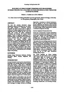
To evaluate the impact of the number of processors on the simulation speedup factor, we executed the software DCT with different configurations of processor number (from 4 up to 16 processors) at the PVT-TA sublevel. The instruction and data cache size varied from 256B to 32KB.
Figure 8. Interconnect contentions in PVT-TA and CABA for the DCT application
Figure 7. Simulation speedup in PVT-TA for the DCT application with 4 processors
Fig 7 demonstrates that PVT-TA makes it possible to accelerate the simulation by a factor of up to 18. Second, adding processors increased this speedup factor due to the amplification of communication between the processors and the memory modules. Up to this point, we have focused on the usefulness of our PVT-TA sublevel for performing functional validations with an interesting simulation speed factor. This sublevel may also be useful for dynamic contention monitoring. In this way, it is possible to detect the moment at which a communication bottleneck occurs in the interconnection network. Fig 8 presents the total number of cumulated contentions during the execution of the application. This result is obtained from the soft DCT executed on a platform with 4 processors and 4KB cache sizes. From this figure, the following remarks can be made: first, CABA and PVT-TA curves are close to each other. Second, this figure allows detecting moments at which a communication bottleneck occurs in the interconnection network. In our case, there is an important increase of contention up to 20000 cycles. Beyond this value the amplification is less important. To evaluate the speedup gain due to the processing part only, we rewrote the DCT application to avoid data cache misses entirely and to reduce instruction cache misses to a negligible number. This application is executed using PVTTA on our platform, the number of processors was varied from 4 to 16 with 32KB caches. The speedup factor obtained was independent of the number of processors and, more importantly, remained constant (close to 5.4). The results of this experiment confirm that the minimal speedup factor for this application at the PVT-TA level is close to 5.4. Consequently, the rest of gain obtained from this sub-
level is due to the communication part. Despite its performance in terms of speedup, the PVT-TA sublevel suffers from a significant performance estimation error. As shown in Fig 9, when the number of processors increases or when the cache size decreases, communication becomes more significant and estimation error increases. This error can be as much as 28% for 16 processors and 256B cache size. As explained in section 5, this is because the MPSoC behaves differently with PVT-TA in terms of the contentions in the interconnection network.
Figure 9. Estimation error in PVT-TA
6.3 Simulation results using PVT-EA Several experiments, using the same applications and the same configurations as previously, were conducted to evaluate the performance of PVT-EA. In the developed model, we again used the VCI protocol specifications. The performance error with PVT-EA was reduced to zero for all the tested configurations. The reason behind this result is the using of in-order scaler processor. As our processor model is instruction accurate, interactions at the pipeline level are not taken into-account. Consequently, at this level the processor model could be replaced by a cycle accurate model,
13th IEEE International Conference on Embedded and Real-Time Computing Systems and Applications(RTCSA 2007) 0-7695-2975-5/07 $25.00 © 2007
if an out-of-order superscalar processor is to be used. This point is proposed as a possible extension of the project. The speedup decreases by less than 30% compared to PVT-TA (Fig 10).
6.4 Modeling effort Our approach also proved interesting in terms of modeling effort. It would allow designers to develop simulation platforms in less time. Using such a tool early in the design process reduces the exploration space, shortens the time-tomarket, and increases the design team’s productivity. Table 3 presents the modeling effort, in terms of lines of code (LOC), required to design an MPSoC platform for the three approaches: CABA, PVT-TA and PVT-EA. Given these results, the modeling effort using PVT-TA and PVT-EA is reduced, respectively, by a factor of 34.8% and 26.4%.
Figure 10. Speedup comparison
7
Conclusion
Modeling MPSoC architecture early in the design process decreases the developmental complexity of such systems and accelerates the design space exploration. In this paper, we propose a new PVT approach, with two sublevels namely PVT-TA and PVT-EA, intended to increase the speed of MPSoC simulation. Several component models have been developed using these two sublevels and enhanced with performance estimation tools to provide accurate execution time estimates. Simulation results demonstrate the complementarity between the PVT-TA and PVTEA models. The first produces a higher simulation speedup factor and an average level of accuracy, while the second provides a more accurate estimate within a reasonable simulation time. Future research will focus on several areas. First, we plan to apply the same methodology to more complex architectures (VLIW and superscalar processors). Second, we hope to enhance simulation models with energy estimation tools for reliable design space exploration.
Table 3. Comparison of modeling effort Abstract level CABA PVTEA PVTTA
Proc 1578 1486 1259
Modeling effort(LOC) Cache Inter Mem 553 399 312 244 177 183 238
176
180
Reduction (%)
Total 2842 2090
26.46
1853
34.80
References [1] F. Balarin, Y. Watanabe, H. Hsieh, L. Lavagno, C. Passerone, and A. Sangiovanni-Vincentelli. Metropolis: an integrated electronic system design environment. IEEE Computer, 36(4), Apr. 2003. [2] R. Ben Atitallah et al. Estimating energy consumption for an MPSoC architectural exploration. In ARCS’06, Frankfurt, Germany. [3] L. Benini et al. MPARM: Exploring the Multi-Processor SoC Design Space with SystemC. Springer J. of VLSI Signal Processing, 2005. [4] L. Benini et al. SystemC cosimulation and emulation of multiprocessor SoC designs. IEEE Computer, vol. 36, no. 4, April 2003. [5] CACTI home page. http://research.compaq.com. [6] L. Cai et al. Transaction level modeling: an overview. In CODES+ISSS ’03, New York, USA. [7] G. Cote, B. Erol, M. Gallant, and F. Kossentini. H.263+: Video Coding at Low Bit Rates. IEEE Trans. On Circuits And Systems For Video Technology, November 1998. [8] A. Donlin. Transaction level: flows and use models. In CODES+ISSS ’04, Stockholm, Sweden. [9] F. Fummi et al. Native ISS-SystemC integration for the cosimulation of multi-processor SoC. In Date’04, Paris, France. [10] D. Gajski et al. SpecC:Specification Language and Methodology. Kluwer, 2000. [11] F. Ghenassia. Tansaction level modeling with SystemC. Springer, 2005. [12] GRACE++. System Level Design Environment for Network-on-Chip (NoC) and Multi-Processor platform (MP-SoC) exploration. [13] T. Groetker et al. System Design with SystemC. Kluwer, 2003. [14] D. Kim, Y. Yi, and S. Ha. Trace-driven HW/SW cosimulation using virtual synchronization technique. In Design Automation Conference’05, Anaheim, California. [15] R. Krishnan et al. Design of a 2D DCT/IDCT application specific VLIW processor supporting scaled and sub-sampled blocks. 16th Int. Conf. on VLSI Design, 2003. [16] H. Lee, B. Lee, Y. Lee, and B. Kang. Optimized VLSI design for enhanced image downscaler. In 2nd IEEE AP-ASIC 2000, Cheju Island, Korea. [17] C. Loeffler et al. Practical fast 1-D DCT algorithms with 11 multiplications. In ICASSP’89, Glasgow, UK. [18] MIPS Technologies Consortium. http://www.mips.com/. [19] S. Mohanty, V. K. Prasanna, S. Neema, and J. Davis. Rapid design space exploration of heterogeneous embedded systems using symbolic search and multi-granular simulation. In Conference on Languages, compilers and tools for embedded systems, Berlin, Germany, 2002. [20] S. Pasricha, N. Dutt, and M. Ben-Romdhane. Fast exploration of bus-based on-chip communication architectures. In CODES+ISSS’04, Stockholm, Sweden. [21] SoCLib project. 2003. http://soclib.lip6.fr/. [22] E. Viaud, F. Pecheux, and A. Greiner. An efficient TLM/T modeling and simulation environment based on parallel discrete event principles. In DATE’06, Munich, Germany. [23] Virtual Component Interface Standard. http://www.vsi.org/.
13th IEEE International Conference on Embedded and Real-Time Computing Systems and Applications(RTCSA 2007) 0-7695-2975-5/07 $25.00 © 2007