provided by, e.g., Synopsys or Viewlogic, support the specification and synthesis ... circuit synthesis tools, such as e.g. SIS [BLM+92] from UCB or ASSASSIN ... computer technologies such as software engineering, database design, and visual ...
20 An object-oriented CAE Framework for asynchronous Circuit Synthesis U. Baake and S. A. Huss Integrated Circuits and Systems Lab. Department of Computer Science Technical University of Darmstadt 64283 Darmstadt, Germany {baake, huss }@vlsi.informatik.th-darmstadt.de Abstract The paper presents an interactive OSF /Motif-based design framework for high-level specification, analysis and synthesis of asynchronous control c:irc:uits. As novel contributions we propose an object~riented graphical design environment including interfaces to external state of the art asynchronous circuit synthesis tools. The proposed design environment represents a powerful CAE design system including features like geometric representation of abstract graph-based input specifications, menu-based command entry, user-defined configuration of input devices and a comprehensive set of visualisation and manipulation commands. Thus, by using this system, a c:irc:uit designer is able to specify and visualise asynchronous circuit behaviour on a high abstraction level and synthesise the corresponding logic using the built-in algorithms as well as other available non-graphical synthesis tools.
1
Introduction
In the domain of interface circuitry, where the use of a global clock is rarely applicable, design methods for asynchronous circuits have recently gained an increasing interest in the logic synthesis community [LL91][LS93][Men90][MM94]. By using design methodologies for locally synchronous and globally asynchronous operation of data processing [Bor89] problems related to limited throughput, clock skew, and clock distribution may be avoided. Even in this restricted domain, asynchronous design has been considered as time--consuming and difficult because of the lack of both, a good formal specification and of appropriate synthesis and verification tools. Formal specification of asynchronous circuits is not that easy because behaviour such as concurrency, sequencing, conflict, timing constraints and data-dependency is difficult to specify in a way that is both, natural for designers and at the same time appropriate for formal analysis or verification. In contrast to synchronous design, where powerful CAE environments, such as those provided by, e.g., Synopsys or Viewlogic, support the specification and synthesis process, available asynchronous circuit synthesis tools, such as e.g. SIS [BLM+92] from UCB or ASSASSIN (YVL93] from IMEC, use an alphanumeric design entry only.
In this paper we present an object-oriented, interactive design environment that supports automated asynchronous circuit design starting from a behavioural graph-based problem specification called signal transition graphs STGs [Chu87]. This formalspeclfi.cation form is exploited in other well-known synthesis tools, e.g. [BLM+92], too. Thus, the implementation of well defined
F. J. Rammig et al. (eds.), Electronic Design Automation Frameworks © Springer Science+Business Media Dordrecht 1995
200
Part Seven Special Design Environments
interface layers allows specification-import and data-export between the proposed framework and e_g_ SIS or ASSASSIN. A powerful component for visualizing and beautifying graph-based specifications allows for a comfortable processing of imported non-graphical STG specifications. Using the OSF /Motif-based graphical front-end of the framework for llexible design capture and manipulation, a designer can use proprietary algorithms for analysis or synthesis as well as other well-known synthesis methods by exporting the specification according to their requirements. In addition to the object-i>riented representation of STGs [BH93], we introduce algorithms for constructing geometric representations from textual specifications. This is essential for importing and visualizing graph-based textual specifications within the graphical front-end of the framework. The automatic generation of drawings of graphs has important applications in key computer technologies such as software engineering, database design, and visual interfaces.
The paper is organized as follows. In Section 2, the specification form used for describing interface behaviour is brie1ly introduced in a formal way. In Section 3, we give an overview for the main components of our system, called Graphical Asynchronous Circuits Environment. In Section 4 a more detailed description of the GRACE front-end is outlined, while Section 5 describes the analysis and synthesis parts, respectively. In Section 6 the import and export interfaces of GRACE are described. An example of a complete design flow, processed by this CAE framework, concludes the paper.
2
Design specification
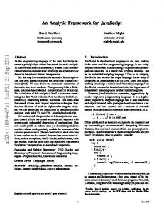
In this section we give a brief introduction into signal transition graphs and show that this specification is very well-suited to describe asynchronous circuit behaviour. STGs, introduced independently in [Chu87] and [RY85], represent a graph-based methodology for the specification of speed-independent asynchronous digital controllers. An STG provides an appropriate representation of concurrency. In addition its natural timing-diagram-like specification makes it easy to describe interface communications with signals as outlined in Figure l. An STG E = (T, P, F, mo) is an interpreted Free Choice Net (FC Net, i.e. subset of a Petri Net), which is expressive enough to specify concurrency or choice, but yet simple enough for analysis. The set of transitions T is interpreted as the set of signal transitions S X {+, -}. S denotes a set of signals, where for every signals E S a rising transition s+ and a falling transition s- is associated, respectively. s' denotes any transition of signals. P is a set of places that can be used to specify conflict or choice and F ~ (T X P) u (P X T) represents the llow relation between transitions and places. The marking is an integer labeling of the places m : P -> 1N, denoting the number of tokens in a place p. mo represents the initial marking of E. The preset of a place or a transition z E PuT is given by ·z = {yl(y, z) E F} and the pDstset of z is denoted z· = {yl(z, y) E F}, respectively.
A transition t is said to be enabled, if 'rip E ·t: m(p) ~ 1. This is denoted as m[t). The set of all enabled transitions is then :F = {t E T I m[t)}. An enabled transition may fire according to the Petri Net firing rule. A marked graph (MG) is a Petri Net, where each place p has exactly one predecessor transition, denoted as source(p), and one successor transition, called target(p). It is usually represented by a directed graph G, where the vertices correspond to transitions and the arcs to places. An STG/MG is an STG that is derived from an MG.
201
An object-oriented CAEframework
f/
C@>
[3,8]
[10,~t'
[5,10]
(a)
Speed independent TO specification ,
,
,
x._.~"··
W
Y... .
.
WJ
,..
.
wr
.
z ... ~"" .. .. .,.. .. . 03
(b)
10 15
: : ::
25 30 3538
::
45 50
y-
~
@
t
j:/z+
z+
[5'10~
Y+
f~1> jJ/x-
[5,30]
9~1>
··.Y+
"-
®
[10,3;;'X-
(c)
®
z-
(T)STG specification
60 65 70
(d)
'·,.Y+
"-
/x+ ~
CITB:>
/x+
@>
/x-
Y-
/x-
SG representation
Timed TO specification (minimum firing times)
Figure 1: Behavioural design specifications In order to include additional timing information related to signal transitions, STG models could be extended [BH94][Van93] [VGL94] as to specify timed interface circuits by assigning lower and upper bounds of the firing time on each arc p of an timed STG, denoted as b(p) and B(p), respectively. In Figure 1a,b two different timing diagrams are presented: a speed independent version corresponding to the STG without timing information on its arcs and a timed version. For a detailed description of scheduling and firing transitions by including timing intervals in STG specifications, denoted as TSTGs, we refer to [VGD92][BH94]. A state graph (SG) t = (Ms, T, 5, mol may be derived from E by performing a reachability analysis according to the Petri Net firing rule [Chu87]. The transformation of minto m' by firing an enabled transition t, is denoted as m[t}m' ¢> m' = 5(m, t) with the partial function 5: Ms X T --> Ms. Ms = {m : S --> {o, 1, R, F}} denotes the set of all states, where each vector (m(l), m(2), ... , m(n)) specifies the value of each signal E S of the system when the system is in that state. The initial state is denoted as mo. Figure Id shows the complete SG representation of the STG specification outlined in Figure 1c without including the timing information on the STG arcs. The reduced SG derived form the timed STG (TSTG) is given by removing the dotted states and arcs from the SG in Figure 1d. For more information on deriving reduced logic implementations from timed input specifications we refer to, e.g., [MM93].
s,
Specification of delay insensitive circuit behaviour may be denoted in a completely different way to the outlined STG method. First, language-based specifications such as communicating sequential processes (CSPs) [Mar90], and second by means of asynchronous finite state machines (AFSMs). CSPs seem to be well-suited for the representation of large designs on a high abstraction level but problems may arise when attempting to specify concurrency within a process. Asynchronous finite state machines [CL93][YDN93] have already been successfully used for hazard-free synthesis of asynchronous controllers, but neither CSPs nor AFSMs incorporate timing constraints as it is usually required for a consideration of wire and environment delays [HM90] [MM93] [BH93].
202
3
Part Seven Special Design Environments
The CAE framework GRACE, an overview
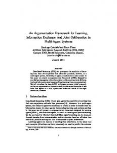
In the following section we give a description of our CAE framework for asynchronous circuit synthesis. The Graphical Asynchronous !;.ircuits Environment (GRACE) consists of five main components as depicted in Figure 2.
The object-oriented data administration is central to all components. One important reason for using an object-oriented representation is the introduction of independent layers of object classes. Therefore, we separate the universal data structures, which include new object-oriented abstract graph structures as well as powerful C++ class libraries for X-Window based graphical representations, and the problem specific data objects like, e.g., STG or state graph (SG) representations. A more detailed description of the general object-oriented concepts may be found elsewhere [BBH94]. The OSF /Motif-based graphical front-end consists of the powerful STG editor SignEd and of the wavefront postprocessing tool TimEd that handles the visualization of the equivalent timing diagram while editing a protocol specification in form of an STG. Further on, TimEd visualizes the results from exercising timing analysis algorithms in order to calculate the schedule of all signal transitions of an STG specification, as outlined in Figure 1, or to determine precedence relations between particular transitions. The import/export tool ImEx is responsible for the communication with other STG-based synthesis packages. These graphical front-end was implemented using the universal C++ class library proposed in [BBH94]. One of the new features of this library is object representation in Adobe's Postscript
Graphical Asynchronous Circuits Environment
Data objects
.-
.rn:xJelSIS-STG ..... b
.CUpiUcd
pla+ba+b-e+
STG based syntheSiS tools
Structural synthesis
Figure 2: Components of GRACE
203
An object-oriented CAEframework
language. Thus, each imported STG specification and its corresponding timing diagram can not only be visualized, but also be represented in Postscript, a feature, which is important for documentation and visual validation. The analysis component hosts a library of algorithms for the assessment of the problem specification in STG terms. Since initial specifications of application specific protocols are not necessarily hazard-free or even consistent [LKS91], powerful analysis means are mandatory to unveil several problems, such as non-feasible initial conditions or wrong schedules during protocol operation [BH94]. Finally, the synthesis component produces the structural description of the logic circuits (netlist) according to the validated STG representation of the communication protocol.
4
The graphical front-end
The graphical front-end of GRACE includes two main components: an STG editor SignEd outlined in Figure 3, and the wavefront postprocessor TimEd, as depicted in Figure 4.
4.1
SignEd
The editor SignEd represents an interactive X-Window-based graphic tool allowing for userfriendly specification of STGs in order to obtain a clearly arranged representation of the communication protocol. Some of its features are menu-based command entry, user-defined configuration of input devices, and a set of visualization and manipulation commands, such as node
[II.
IdA
tl~
~TI..,;
IN'u' IIIXIiIt: ta~1tIdr.
Figure 3: The editor SignEd
1•._