An Object-Oriented Framework for Water Resource Planning . Knut Alfredsen
Bjørn Sæther
Department of Hydraulic and Environmental Engineering The Norwegian University of Science and Technology E-mail:
[email protected]
Water Resources SINTEF Civil and Environmental Engineering. E-mail:
[email protected]
Abstract
A common tool for obtaining the desired modularity and reuse in software development is the application of object-oriented analysis and design methods. Objectoriented methods are also gaining more use as a complete modelling tool in hydrology and hydraulics (e.g. [20], [21], [19], [14], [15]). Considering the object-oriented structure of the hydrological system and the increasing level of integration needed in a modern hydroinformatics system, this approach should give clear advantages in this field. Many of the rivers in Norway are regulated for hydropower production. The typical Norwegian hydropower system consists of reservoirs for water collection and storage combined with tunnel systems leading the water to a power plant, which often is located several kilometres away from the reservoir. In many cases, reservoirs are located in the headwaters of a river system. The operation of the reservoirs therefore plays an important role in the water distribution in the system, both for flood operation and for the flow regime in the regulated river. This paper presents a combined flood routing, production and impact assessment model implemented as a set of modules (classes) that can be combined to closely represent the natural system. The model is designed using an object-oriented methodology and implemented using the C++ programming language. The important consideration has been to create a system that easily can incorporate new developments and changes in modelling strategy. A design based on reusable components and frameworks has been used to provide a foundation for this work and for our future developments in this field. The important processes that needed attention in this modelling system were: • Runoff calculations • Routing calculations in rivers, lakes and reservoirs • Water transfer and capacity calculations • Power production • Reservoir operation. The processes are either implemented in the scope of this project, or earlier developments have been incorporated in the flood model to solve one of these tasks.
This paper presents an object-oriented toolkit for building computer models for water resource planning. The focus is on building a program for flood calculations in river systems with several reservoirs and water transfer structures. The foundation for the flood model is a framework for building hydrologic models. The general framework provides the user with tools for describing the structural components of the hydrological system, their relation in the system topology and controlling the behaviour of the system during simulation. Hydrological models are often data intensive, and the framework is equipped with tools to handle both time series and spatially-distributed data in an efficient way. During development, effort has been put into supporting future changes and extensions to the model system, as well as creating sound reusable components that will benefit future development and maintenance. A flood modelling application in the Norwegian river Gudbrandsdalslågen in described to illustrate the use of the toolkit.
1. INTRODUCTION Computer models have been used as planning tools in water resources management for over three decades. The fields of computational hydraulics and hydrology are well researched, and many models and algorithms are already implemented to solve different aspects of the hydrological system (e.g. [3], [2]). For a broader water resource planning situation it is necessary to combine and interact with several of these process models to create a program system that covers all water uses in the river system. This approach requires a modular structure in the system, allowing different sub-models to be interconnected depending on the natural system at hand. Another important aspect that must be considered in new developments is creating software elements that can be reused in future projects. The use of reusable components gives benefits both regarding development time and reliability of the software produced [12]. This also will reduce development and maintenance cost for the project.
1060-3425/98 $10.00 (c) 1998 IEEE
2. MODEL REQUIREMENTS 2.1. Flood model functionality The objective of the model is to route water through a system of rivers, lakes and reservoirs. The model should be capable of using both hydraulic and hydrologic routing methods [17] dependent on the characteristics of the reach. In addition to the routing calculations, the model should be able to handle the water transfer and reservoir operations that are connected with a hydropower system, since both control and operation of the regulation arrangements are important for flood propagation in a regulated watershed. The main requirement for the model itself and the main objective for the selected design was to create a system that as closely as possible represents the river system that is to be analysed. The model should be able to represent all elements in the river system and connect these together to represent the water flow in the system. The structure of the model should easily permit the user to create a more detailed model of parts of the river system, or if needed aggregate parts into larger units if that is desirable. Another requirement for the model was that it should be possible to use various calculation methods in different reaches depending on the availability of data and the physical characteristics of the reach. In a routing model the question of using a full dynamic equation or simplified forms of the equation must be addressed [8]. In many cases there will be a need for both approaches due to the limitations of detailed data in some reaches. We therefore want to be able to define reaches with detailed hydraulic simulation methods installed, while other reaches may have simpler calculation methods. Models in hydrology and hydraulics are data intensive, and an efficient data handling system is needed. The routing procedures needed require both spatial data in the form of geometry information and temporal data structures during operation. The variables transported between the components should be user controlled. It should be possible to define which of the calculated quantities that is to be transferred between the objects in the model. In the case of the flood model this will be discharge and water level, but for future application we may want to include other variables in the transport process.
2.2. System design requirements A set of requirements for the design was defined based on the proposed functionality of the model. The basic requirements for the model construction were as follows:
• Strongly modular structure. • Reusability of existing tools and providing reusable components for future developments. • Adaptability to user needs regarding data and methods. • Easy extendible with future algorithms or methodologies • Connectivity to existing models and systems To be able to build a system model that would represent the real world system as closely as possible, the model must have a strongly modular structure. Each of the modules must contain necessary information and operations in the internal structure. The modules must have a simple interface to access the information. The encapsulation of information in an hydroinformatics system is described by Abbott [1] and is handled by using the encapsulation mechanism in the object-oriented design. By building on defined interfaces and using inheritance, the user can integrate new modules into the existing hierarchy. Another important feature in the modular system approach in this project is the separation of calculation methods (the actual hydrologic and hydraulic processes) from the components that describe the structure of the system. This allows us to change the calculation method used without any code changes inside the structural components themselves. An important consideration in any software project is the ability to reuse components during development. Reuse was a very important consideration in this project, and effort has been put into the creation of components that could be reused in new projects. Experience with earlier projects such as using the data containers for time series and curves, shows that reuse gives a significant reduction in development time and also in the time spent on correcting errors. Both these factors contribute to a reduction in overall project costs. One of the goals in this project was to make sure that new classes would add to our library of reusable components. Experience with earlier developments led us to put emphasis on user configurability. This was stressed during development, mainly by allowing the user to define data, computational methods (processes) and transported parameters without requiring changes in the base structures of the program. To facilitate this, the base structures will support data containers that can accommodate a variety of user-defined data structures and data types without any changes being required in the base component itself. By separating the implementation of computational methods from the structural components we allow both the additions of the user’s own developments and externally developed algorithms as computational methods in the flood model. Taking the amount of work done in computational hydraulics into account, it is important to
1060-3425/98 $10.00 (c) 1998 IEEE
be able to consider the existing tools for inclusion into the model. The need for future extensions of the model is maintained in two main ways. Inheritance hierarchies are used throughout the code when this was applicable, and most of the storage classes are defined with generic interfaces through the use of templates. In the class hierarchies, key functions are defined as pure virtual requiring re-implementation before use. The combination of this with an abstract base class prevents the user from developing classes that will not function in the context of the model. To take advantage of previously developed program systems, the model design allows for inclusion of these both as internal methods and as external data providers in the system. If an external program is to be used, an interface method must be derived from the method hierarchy that encapsulates the external program system. This interface will make sure that data is retrieved from the structure components and placed on the format required by the external program, and it will control the execution inside the model system. In some cases it has been necessary to alter the simulation strategy to accommodate the external program. This is done by altering the simulation control system. The model was designed in two steps, first a basic framework for hydrological modelling was designed and implemented [4]. This will work as a foundation for the flood model and also for future projects in this field of model development. The framework design supports both reuse of objects and a strongly modular design [7]. The flood model was created partly by using components of the framework directly and partly by developing new components in the framework scope that was particular to the flood model project.
2.3. Related work Several program systems exist for flood routing, e.g. NWS Dambrk [17] and MIKE11 [10]. These are mostly based on solving the full St.Venant equations. The most advanced of these models can handle river networks, reservoirs and flooding over areas adjacent to the river channel. Most lack support for catchments, water transfer systems and hydropower-plants. By utilising the process separation of the flood model, it is possible to integrate one of these systems into the flood model if needed. Through the River System Simulator project [16] a common data exchange was developed for a selection of well-known models, thereby providing an integration platform. Compared to the flood model, this approach still operates with separate models, lacking the seamless integration over a common river system description. Several approaches have been made to utilise object-
oriented methods to create flexible models for river system analysis. Shane et al. [21] present a system for reservoir and power plant modelling. Through the use of specialised controller objects this system can simulate the power system both through optimisation and rule-based control. Some routing methods are also available for the river reaches. The HEC-HMS system [9], a successor to the HEC-1 model from the US Army Corps of Engineers Hydrologic Engineering Center, is a precipitation-runoff model based on a detailed basin description. The HECHMS model provides the structural elements to build the basin model and a set of hydrologic methods for computations in each element. The Process Integrating Network (PINE) model [19] models precipitation-runoff in catchments using a node network representation of the hydrologic system. PINE supports inclusion of user defined methods, and through a semi-distributed approach to modelling it provides opportunities to model different types of land use. PINE also has been used for runoff calculations in urban areas. Changes in land use and urbanisation can be important factors in flood calculations, and plans are made to integrate PINE into the flood model to handle sub-catchment processes. Jamieson and Fedra [14],[15] present the WaterWare system that uses objects to describe the real world system in a similar way as the flood model. Through the use of ModelScenarioObjects, data can be retrieved from the general model and be prepared for use in a simulation system. This procedure resembles the River System Simulator model integration and also the external program integration used in the flood model. The WaterWare system provides a comprehensive GIS and database support. Compared with these, the flood model will offer precipitation-runoff modelling, routing methods and hydropower system operation in one package. The ability to define the computational methods and the transported matter freely, gives us a powerful platform for future model extensions. 3. MODEL COMPONENTS
3.1. Overview The components of the flood model are presented in the following sections. This includes both relevant parts of the underlying framework and the derivations that were made when the flood model was created. The underlying framework structure is divided into four main parts: • Structural components and system topology – defines the elements of the hydrological system that is to be modelled, e.g. rivers, lakes and catchments. The basic framework structure contains the most common elements, in actual applications it may be necessary to derive application specific elements.
1060-3425/98 $10.00 (c) 1998 IEEE
•
Computational methods – contains the foundations for defining the mathematical models used to represent the processes in the system. The base framework defines the interface to the computational methods. • Data containers – a set of classes for data storage and handling. This set of components also contains special data containers made for some of the mathematical models used in the framework, e.g. finite element grids. • Simulation control – the overlying system that defines the simulation strategy and controls the execution of the model. The flood model itself is created partly by using components of the framework directly and partly by extending it to create the necessary computational methods and special structural components needed in this model.
3.2. Structural components The structural components are the core of the modelling system. The structural component describes the elements of the real world hydrological system with their state, structure and behaviour. In object oriented terms the state and structure are defined by the internal variables, the behaviour is defined by the computational methods that are related to the component. In addition, the structural components can be related to each other in a network that describes the topology of the hydrological system.
natural element in the hydrological system. A similar constraint is set on the Waterway class, which is a common base for all transport reaches. A set of functions are defined as virtual in Hydcomp, these can be implemented in each of the derived classes to reflect the actual behaviour. The functionality for transport of matter between components is defined and given a default implementation, but the components are also defined as virtual so that they can be redefined if special cases arise. The Hydcomp class also stores links to its upstream and downstream neighbours and the storage and retrieval system for data connected to the object. Data can be added to the structural components as required data that can either be part of the physical category (e.g. cross-sections for river reach) or state parameters (e.g. discharge or waterlevel). The state parameters are designed to hold the data that is updated during the computations. The data containers are defined in a template structure and they can store both aggregated data in the form of classes and ordinary data types. All computational methods are separated from the structural components and can be added at need by the user. This feature is described more closely Section 3.3. When data and computational methods are added to the structural component, we have a complete computational element that can be inserted into the network. Figure 2 shows the structure of a computational element.
Computational Method
Link to upstream element
Structural object
State
Link to downstream element
Physical data
Figure 2 Computational element
Figure 1 Hierarchy of structural components. Notation after Booch [6]. The structural components are defined in a hierarchy with a common base (Figure 1). The Hydcomp (base) class is the common node for insertion into the network structure, and as an abstract base for deriving new structural components. The abstract definition of this class prevents the user from using it directly, it is merely a foundation for the development of classes that represents a
The transport of matter between components is defined in functions found in Hydcomp. As mentioned, these functions have a default implementation but it is also possible to redefine them if necessary. A special control system makes sure that the exported item from the upstream component is correctly transferred to the receiving item in the downstream component. The mapping is user defined and any structure can be transported as long as it has equality and addition operators properly defined. Control functions can be
1060-3425/98 $10.00 (c) 1998 IEEE
added to verify the transport. This is specially needed in the case of a downstream division (a downstream branch), or if the values should be balanced during a computational procedure. A similar control object handles a mapping between each component and the corresponding legal data types for this component. This is invoked each time a new data element is inserted, and if this is not a legal data type the insertion will be aborted. The export and mapping controls are implemented as global objects using the singleton pattern[11]. One of the main considerations in the design of the structural components was to create a system that could define a river system with data and interactions without being linked to any specific computational application. The structural hierarchy can therefore form a basis for different applications in water resource planning. In addition, the structural elements and the topological information can be used as a tool for visualisation of the river system and as a front end to data. One of the future plans for this system is to investigate the possibility to store the system in an object-oriented database. When the computational elements are defined for the river system they are inserted into a network structure that defines the natural topology of the river. This is implemented in the form of a directed graph structure where each node represents an element in the hydrological system. An iterator is made to traverse the structure during calculation. The traversal procedure establishes a list of nodes with nodes without upstream dependencies first. This is done by executing a topological sorting algorithm in the iterator. The resulting list of elements is traversed and the calculation methods for each element are invoked. Special considerations must be taken in cases where a downstream element is influencing the upstream neighbour (e.g. in cases of backwater effects during a routing calculation) or cases where the default flow direction is changing in flat areas during a simulation.
3.3. Methods During the model design phase we specified a system with separation between the computational methods and the classes that describe the structural components in the system. The main reason was to find a way to remove the code of the calculation methods from the classes that describes the structural components. This gives the user the opportunity to add new methods to the model without changes in the component source code. Another benefit is the possibility to have an array of methods to choose from, providing the user with the opportunity to build a model with computations that match the detail needed and data available for each reach. The flexible method connection is achieved by building a separate hierarchy of computational methods
and connecting these to the structural hierarchy through their base classes. The user can derive new computational classes from the hierarchy and automatically have them ready for inclusion into the structural components. The separation method we selected closely resembles the Strategy pattern defined in [11]. All the details about the connection and operation are hidden inside the base classes out of view from the user of the system. Figure 3 shows a part of the hierarchy and the relation to the structural components
Figure 3 A part of the computational method hierarchy with link to the base component of the structural hierarchy. When developing a new computational method, a set of virtual functions defined in the base class for computational objects (CompObject) must be implemented. These functions include the calculation function, the verification function and data retrieval function. The data retrieval function is called when the method is connected. If the data needed is not present in the structural component, the user gets a message back either to add the needed data or select a method with a reduced data requirements. Parameters that are specific to the mathematical method that is implemented will be transferred in a method specific data block. This approach has proved to be a very effective way of building applications with a flexible number and types of computational methods available. Methods can be added depending on the characteristics of the reach that is to be computed, the available data and the needed degree of output.
3.4. Data One of the most important data types in hydrological models is time series. Hydrologic simulation models use time series both as input and output. An example is the discharge series produced by the flood model for selected points along a river, or the input series of precipitation and temperature to a catchment model.
1060-3425/98 $10.00 (c) 1998 IEEE
In order to obtain modularity and reuse of software components, classes for time series have been developed, providing the user with a consistent interface to time series data. These classes have been developed in accordance to the same principles as the String and SubString classes in the National Institute of Health (NIH) class library [13]. Generally, there are two main types of time series, one having constant time interval (regular series) and the other having time stamped event data. Template versions of regular and irregular time series classes have also been made in order to keep time series of user defined data. For example, pictures are collected with regular intervals and stored in a specialised image class. Then, each individual image is being inserted into a regular time serie of image data. The time attribute of the image is used to find its position in the time series. The main time series classes are RegulerTimeSerie and IrregularTimeSerie which keeps the time series data and its attributes for time series having regular time interval and series having irregular spaced or event data respectively. They share a common abstract base class, enabling both types of time series to be inserted into collection classes like lists and stacks. The time series data classes inherit from a base class that allows them to be part of a model-view controller structure. This conforms to the “observer” pattern [11]. This facility opens the way for dynamic presentation of results during a simulation, as well as a dynamic presentation of environmental data recorded by an automatic data acquisition system. Specialised classes for time series transformations have been developed. They take one or more time series data classes as input, either directly or through a Model-ViewController relationship. Several transformation classes have been developed: • Functional transformations. This transformation function uses an (x,y) curve to produce a new time series from the original one. • A time series calculator which has been created to support simple arithmetic transformations of regular time series. • Sorting and creation of duration curves. • Time series statistics. A time series collector is developed in order to store and manage time series that are being generated by the model. A hierarchy of input/output classes has been developed in order to read and write time series data from different databases and file formats. No input or output functions have been implemented in the data classes themselves, this ensures that no data classes have to be modified or extended when new file formats are developed. In hydrological models, two-dimensional and threedimensional curves are frequently used. A set of classes
for these types of data has been developed, giving the user a consistent interface to this type of information. Curve and surface data classes have similar properties as the time series classes regarding dynamic presentation through a Model-View-Controller interface. Curves and Surface data classes are equipped with the same type of separate I/O structure as the time series classes. Similar data structures exist in the system to handle the spatial data needed to describe the structure of the components. These include cross sectional data from rivers, triangular grid structures and some other grid structures made for numerical modelling.
3.5. Input/Output system Data for the simulation models can be handled by several file systems and relational databases. In order to give flexibility, and a possibility for the end user to choose storage format, each individual component in the entire model may be able to read from and save itself to a variety of file formats and database systems. The problem is that every file format or database will need a unique piece of source code for the structural objects, computational objects and container objects in order to save and restore them. This leads to a huge amount of source code in the model only for the purpose of reading and writing objects to external storage. The solution is to separate the input / output code from the classes of the model. Every data class type in the application will have one member function for reading, and one member function for writing. A global object named ApplicationSetup keeps information about which input / output system that is in use at the moment. Another utility class named IoFactory, being developed after the factory principle [11], is responsible for the instantiation of the storage class that matches the storage system in use. After having created the storage class which both matches the actual data class and the selected file system, the IoFactory returns that class. A consequence of this approach is that every data class type must have a standalone input / output class hierarchy. This class hierarchy has an abstract base class which holds the input / output interface. For every file system and database we need a concrete class being derived from the abstract base class. This concrete class keeps an implementation of the read and write functions for a specific data class and a specific file system. The advantage is that there will be a consistent interface for external storage that is the same for all file systems and databases, and there will be no need for modification in the data classes when new storage systems are incorporated. The problem is that there will be a need for a new class hierarchy which serves input / output every
1060-3425/98 $10.00 (c) 1998 IEEE
time a new data class or container class is being developed. The application will instantiate only the classes needed due to the actual or selected file system.
functions in the base implementation of the controller, and they can be re-implemented in new derivations of the controller if there is a need to change the operation of the system. A global time control class handles timing in the model. Functions in the Simulation control units provides an interface to the timer with the possibility to define the start and end times of the simulation and the timestep. Currently the model runs with a simple controller that reads a control file as input and runs through the simulation defined in that file. The main objective for creating a controller that is changeable and user defined is the future plans to update the functions of the model in a simulation. Plans include short time optimisation and interactive control of the simulation. Both these tasks will require a modification to the simulation system, and by having a hierarchy of controllers performing different tasks it will be possible for the user of the system to choose a type of simulation by instantiating and activating the controller built for that task. There will also be a need to modify the simulation control unit when third party hydraulic models are incorporated into the system. For some of these models it is not possible to configure them to run on a time step basis to fit into the model. It will therefore be necessary to build a stepwise simulation system that runs the internal methods upstream of the external modelled reach, then runs the entire simulation for the external reach before it continues with time step simulations again. A modification is needed in the simulation control system to accommodate this.
3.6. Simulation control The simulation control unit is the overlying structure that controls the way the program operates and handles all communication with the main program structure. The simulation controller is also defined as an abstract base with several derivations depending on how the simulation is to be carried out. The main functions of the controller are the following: Build system structure This function builds the system structure. Depending on the implementation of the function it can be from file or from an interactive description from the user interface of the model. Verification of structure This function can be used to make a verification of the soundness of the model structure. The function will check the topology for cycles and incomplete structures. The routine will also test the length of the simulation defined in the timer against the available input data to the model. Simulate The Simulation function will activate the topology iterator, create a simulation sequence and execute a simulation for the defined time period. In a future interactive system the Simulate function will be the user’s connection to the simulation system. All the functionality described are defined as virtual
O tta Bø
V ågå va
vra
tn
O tta S jo
a V in
B yg di
s tra
Lå
ge
n
Ga
R e s e rv o ir
us
n
a
L ille h a m m e r
U n re g u la te d L a k e C a tc h m e n t b o u n d a ry R iv e r P o w e r p la n t
H am ar
Tow n D am
M jø sa
T unnel
Figure 4 The Gudbrandsdalslågen catchment.
1060-3425/98 $10.00 (c) 1998 IEEE
•
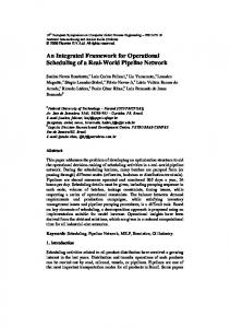
4. Model application During the development phase the model has been applied to smaller cases and pure test data. The base framework has also been used as a foundation for the redesign of the Norwegian physical habitat modelling system [5]. The first actual application of the flood model is now underway, building a model of the Gudbrandsdalslågen river system in southern Norway (Figure 4). The objective of this study is to analyse the flood response of the river system depending on how the regulation installations in the river system are operated during the flood conditions. Four conditions that are influencing the flood levels will be investigated by applying the model: • The inflow to the reservoirs and river reaches from the catchments. • The operation of the reservoirs. This case will include both studies of the effect of different water levels at the start of the flood and the operation of the reservoir during the flood. • Routing of floods through lakes, reservoirs and river reaches.
O tta
The regulation of Lake Mjøsa in the lower part of the catchment. The project goal is to quantify the effect of each of these factors on the flood levels in the river system. Another important outcome of the project will be to define strategies for reservoir operation in flood conditions to achieve flood reduction in the downstream reaches. There are three main tasks that have to be done when the model is to be applied to a system before the actual calibration and running phase. 1. Division of the river system into computational elements. This must be done considering the hydraulic characteristics in addition to the objectives of the study. 2. Collection of the necessary data to describe each of the elements in detail. The data need is also dependent on which method that is to be applied for routing in the elements, in many cases the amount of available data will limit the application of the most advanced hydraulic methods. In such cases the user either has to apply a less detailed method or to go out and collect the data needed for the method that is wanted. 3. Build each of the computational elements and add them to the topology network.
F in n a B ø vra
B y g d in Lågen
S jo a
L ake R e se rv o ir T unnel
H arp e fo sse n
P o w e rp la n t R iv e r re a c h C a tc h m e n t H u d erfo ssen
C o n n e c tio n M jø s a
Figure 5 The model representation of the Gudbrandsdalslågen river system. Local catchments to the objects are not included in the figure. The catchment symbols represent undeveloped parts of the river system that are not treated in detail in the model.
1060-3425/98 $10.00 (c) 1998 IEEE
The divisions of the system into computational units are strongly dependent of the scope of the calculation. In this case the main concern has been to represent the part of the river that is influenced by hydropower developments. The tributaries and upper undeveloped parts of the systems have been represented as catchments that drain into the river system. Tributaries that have reservoirs and power plants are represented in detail in the system. The local catchment for each river reach is modelled and taken into the system at the connection between each element. Data are collected and stored in suitable data containers. These are then added to the respective component. In the first run of the model, simple hydrologic routing methods were applied to the system. Future applications will see hydraulic routing methods used on the most critical downstream reaches of the river system. The next step is to select the methods that are needed and connect them to the structural components. The final step in the model preparation is to build the system topology by connecting each of the computational units to form a complete representation of the complete system. Figure 5 shows the representation of the Lågen that is used for the initial simulations.
5. CONCLUSION AND FURTHER WORK An object-oriented framework for representing river systems has been developed. The framework provides the user with tools for building the system structure and handling data. In addition, a base is made for inclusion of computational methods in the system. The separation of the river system description and the actual calculation methods provides the user with an effective tool for building a variety of simulation models based on a common river system description. The framework has been used in the development of a model system for estimation of floods in river systems with water transfer and hydropower developments. This model is currently in the testing phase. During the project we have encountered several occasions where practical reuse of components has proved to be very effective. In this project the reusable properties of the classes have been of great importance, and we have seen the effect of this in reduced development and error correction time. Furthermore, the ability to build self contained components in the object-oriented system have proved very effective in the design of a program system that can be customised to the river systems which we want to model. By utilising the separated computational methods, we are been able to use the best-suited method for each component in the model. A problem with the current design compared to traditional flood modelling packages is handling of effects that propagate from
downstream to upstream in the topology. Several strategies have been investigated, but at the moment of writing no selection has been made. Currently the model is applied to the Lågen river system, this will be expanded to cover the entire Glomma river system. This is the largest river in Norway, and the Lågen river is a tributary to Glomma. The model system is also selected as the foundation for the integrated river model for this system, which will be used by power companies and authorities as a tool for flood studies. One motivation for this selection is the possibility to later use the model for flood studies in other Norwegian rivers thereby creating a common model system for all flood studies. In addition to flood routing and hydropower operation, the new program system will be expanded with models for changes in land use, river embankments and floodplains, urbanisation and effects of forestry and agriculture. The model will be integrated with a GIS system for data retrieval and presentation. Future fields of investigation also include storage in an object-oriented database and distribution of model processes. Distribution and communication is of special interest since the flood model already will be used in a distributed environment of agencies and power companies. It is therefore interesting to see if it is possible keep the distributed responsibility for data and task in the model and see if it will be possible to integrate this by using Internet and standard methods for object communication.
6. REFERENCES 1.
2.
3.
4.
5.
6.
Abbott, M.B. (1993) The electronic encapsulation of knowledge in hydraulics, hydrology and water resources. Advances in Water Resources 16. P 21-39. Abbott, M.B. (1991) Hydroinformatics. Information technology and the aquatic environment. Avebury Technical, Aldershot, England. ISBN 1-85628-832-3 Abbott, M.B. and Cunge J.A. (1982) Engineering applications of computational hydraulics. Volume 1. Homage to Alexandre Preissmann. Edited by M.B. Abbott and J.A. Cunge Monographs and surveys in water resource engineering; Pittman Advanced Publishing Program 1982. ISBN 0-273-08512-3 Alfredsen, K. and Sæther, B. (1997) An Object Oriented Framework for Creating Models in Hydrology. ACM Sigplan Notices, Vol 32. No 2. P 16-19. Alfredsen, K. and Killingtveit, Å. (1996) The Habitat Modelling Framework. A tool for creating habitat analysis programs. In: Proceedings of the 2nd International Symposium on Habitat Hydraulics. Editors: M.Leclerc, H.Capra, S.Valentin, A.Boudreault and Y. Cote. Quebec City Canada, June 1996, Volume B, P 215-227 Booch, G. (1996) Object Oriented Analysis and Design with Applications 2nd ed. Benjamin Cummings Publishing Company Inc. ISBN 0-8053-5340-2
1060-3425/98 $10.00 (c) 1998 IEEE
7. 8.
9.
10. 11.
12.
13.
14.
Booch, G. (1994) Designing and Application Framework, Dr.Dobbs Journal, February 1994. P 24-30. Cunge, J.A. Holly, F. and Verwey, A. (1980) Practical Aspects of Computational River Hydraulics . Monographs and surveys in water resource engineering; Pittman Advanced Publishing Program. ISBN 0-273-08442-9 Charley,W, Pabst, A. and Peters, J. The Hydrologic Modeling System (HEC-HMS): Design and Development Issues. Computing in Civil Engineering 1995 DHI (1997) MIKE11 overview. http://www.dhi.dk/mike11/ Gamma, E. Helm, R. Johnson, R. Vlissides, J. (1995) Design Patterns. Elements of Resusable Object-Oriented Software. Addison Wesley Publishing Company Inc. ISBN 0-201-63361-2 Goldberg, A. and Rubin, K. (1995) Succeeding with objects. Decision Framework for Project Management. Addison Wesley Publishing Company, 1995. ISBN 0-20162878-3 Gorlen, K.E. Sanford, M.O. Plexico, P.S. (1990) Data abstraction and object-oriented programming in C++. John Wiley & Sons. ISBN 0-471-92346-X Jamieson, D.G. and Fedra, K. (1996a) The ‘WaterWare’ decision support system for river basin planning. 1. Conceptual Design. Journal of Hydrology 177 p 163-175.
15. Jamieson, D.G. and Fedra, K. (1996b). An object-oriented approach to model integration: a river basin information system example. Proceedings from HydroGIS 96. Vienna, April 1996. IAHS Publ no. 235. 16. Killingtveit, Å., Alfredsen, K. and Bakken, T.H. River System Simulator User’s Manual SINTEF NHL Report 1995 17. Maidment, D. Mays, L, Chow, V. (1988) Applied Hydrology. Mc Graw Hill Inc. ISBN 0.07-010810-2 18. Reitsma, R.F. Sautins, A.M. Wehrend, S.C. (1994) Construction kit for visual programming of river-basin models. Journal of Computing in Civil Engineering. Vol. 8, No.3 p 378-384. 19. Rinde, T. (1996) PINE – a hydrological model with flexible model structure. In: Proceedings from the Nordic Hydrological Conference. Editors: O.Sigurdsson, K. Einarsson, H. Adalsteinsson. Akureyri Iceland, August 1996. Volume 1, P 235-247. 20. Solomatine, D. P. (1996) Object Orientation in Hydraulic Modeling Architectures. Journal of Computing in Civil Engineering, vol 10. No 2 April 1996. P 125-135. 21. Shane, R. Zagona, E. A. McIntosh, D. Fulp, T. J. Goranflo, H.M. (1996) Project Object. Civil Engineering, January 1996. P.61-63. 22. Sæther, B. (1996) An object-oriented toolkit for time series handling. In: Proceedings of the second international conference on hydroinformatics. Editors: Müller, A. Zurich, Switzerland, September 1996.
1060-3425/98 $10.00 (c) 1998 IEEE