Sargeant, J.: Lecture notes for the CS 432 course "Further. Information Systems'1. 1988-89 MSc (Method I) in Computer. Science, University of Manchester. Scott ...
AN OBJECT ORIENTED MODEL FOR CONCURRENCY SUPPORT IN ABSTRACT DATA TYPE SYSTEMS
A THESIS SUBMITTED TO THE UNIVERSITY OF MANCHESTER FOR THE DEGREE OF MASTER OF SCIENCE IN THE FACULTY OF SCIENCE
By Asterios I. Fanikos Department of Computer Science October 1989
The trademarks used throughout this dissertation are: UNIX is a trademark of the AT&T laboratories •
SUN is a trademark of SUN Microsystems, Incorporated
•
Chorus is a trademark of Chorus systemes
•
Motorola is a trademark of Motorola Company, Incorporated
Contents
List of Figures
7
Abstract
8
Preface
10
Acknowledgements
11
1. Introduction
13
1.1 The Software Crisis 1.2 The Project Context
13 ,
1.2.1 Aims of the Project 1.3 Structure of the Dissertation
15 16 17
2. Concurrent Object-Oriented Programming
20
2.1 Concepts of Concurrent Programming
21
3
2.1.1 Specifying Concurrent Execution
22
- Coroutines
22
- The fork and join Statements
23
- The cobegin Statement
24
2.1.2 Synchronisation Primitives based on Shared Variables
24
2.1.3 Synchronisation Primitives based on Message Passing
25
2.1.4 Models of Concurrent Programming Languages
26
2.2 Concurrent Object-Oriented Programming
28
2.2.1 Object-Oriented Programming
29
- The C++ Programming Language
31
2.2.2 Concurrent Object-Oriented Models
34
- ConcurrentSmalltalk
35
- The Actor Model
36
3· The European Declarative System Project
39
3.1. The EDS Machine
40
3.1.1 The Flagship Project
41
3.2 The Process Control Language
44
3.2.1 The Process Model
46
3.2.2 The Store Model
48
3.2.3 The Communication Model
48
3.3 A Proposal for a PCL Simulator
ι
50
3.3.1 The Chorus Distributed Operating System
50
3.3.2 The Mapping of PCL to Chorus
54
4. Support Environments and Tools 4.1 Fourth Generation Languages
56 57 4
4.2 Support Environments and Tools
58
4.2.1 The"CADES System
60
4.2.2 The IPSE 2.5 Project
61
4.2.3 The Flagship Support Environment
62
4.3 The EDS Development Route Environment 4.3.1 The Base Model Language 4.3.1.1 The Primitive ADTs
64 67 70
- The Synchronous ADT
70
- The Asynchronous ADT
71
- The Composed ADT
71
4.3.1.2 Developing Systems with BM
5. Modelling of the Base Model Sequential ADT
72
75
5.1 Introduction
75
5.2 The Model
78
5.2.1 The Dynamic Behaviour
78
5.2.2 The Abstract Behaviour
79
5.3 Design
79
5.4 The Base Class
82
5.4.1 The Constructor - Specifying the Context of the Thread 5.4.2 The Destructor 5.5 The Derived Class
83 84 88 89
5.5.1 The Public(interface) Function
91
5.5.2 The Private Function
92
5.5.3 The bm_loop Function
92
5.5.4 The Message and the Coding Scheme
93
5
5-5.5 The Constructor
97
5.6 The Synchronous ADT
98
5.7 The Asynchronous ADT
101
5.8 An Alternative Abstraction Mechanism
104
5.9 Example
106
6. Conclusions and Further Work
110
6.1 Summary
110
6.2 Conclusions
Ill
6.3 Further Work
112
6.4 A Possible Extension to Separate Address Spaces
114
References
117
Appendix
126
A.l The Base Class . .
127
A.2 Class Declarations
129
A.3 Synchronous Stack Object
130
A.4 Asynchronous Stack Object
134
6
List of Figures Figure 2.1: A use of Coroutines
23
Figure 2.2: Synchronisation Techniques and Language Classes
27
Figure 2.3: An Example of Inheritance
30
Figure 3.1: The Flagship Closely Coupled Structure
43
Figure 3.2: PCL Mapping of Tasks and Threads to Processing Elements
47
Figure 3.3: The Chorus Architecture
50
Figure 3.4: Chorus Main Abstractions
53
Figure 4.1: Activities of the EDS Development Route Environment
67
Figure 4.2: A Non-Deadlock Free System
73
Figure 4.3: A Livelock Free System
74
Figure 5.1: BM Translation Route
76
Figure 5.2: Class Hierarchy in the Base Model ADTs' model
81
Figure 5.3: (a) Stack Layout on a Function Call
87
(b) Stack Layout for Thread Initialisation
87
Figure 5.4: Base Model ADT - C++ Class Correspondence
91
Figure 5.5: Communication Message Structure
95
Figure 5.6: Alternative Message Structure
96
Figure 5.7: The Synchronous Object
100
Figure 5.8: The Asynchronous Object
102
Figure 5.9: An Alternative Implementation for the Asynchronous Object
104
Figure 5.10: Class Hierarchy in the Base Model ADTs' Alternative Model
105
Figure 6.1: Models for Shared and Separate Address Spaces
115
7
Abstract
A major area of research in the last decade has been that of concurrent programming languages. The need to design and build powerful, yet flexible computer software systems has led to the development of various contending models. However, no consensus has emerged in the field. Object-oriented concurrent programming is a programming and design methodology in which the system to be constructed is modelled as a collection of concurrently executable program modules that interact with one another by sending messages. Base Model is an object-oriented concurrent modelling language [Sa 89b]. It comprises three primitive data types of component, the synchronous ADT, the asynchronous ADT and the composed ADT. The aim of this research work has been to model the concurrent behaviour of the synchronous and asynchronous ADTs of the BM language. The tools that were used for this modelling were the object oriented language C++ and the Chorus distributed operating system.
8
DECLARATION
No portion of the work referred to in this thesis has been submitted in support of an application for another degree or qualification of this or any other University or other institution of learning.
9
Preface
The author graduated in April 1988 with a BSc in Physics from the Aristotle University of Thessaloniki, Greece. He joined the Department of Computer Science of the University of Manchester in September 1988 to study for the degree of Master of Science by Method I.
10
Acknowledgements
I would like to express my gratitude to: •
My supervisor Prof. Brian Warboys, for his many helpful suggestions and guidance throughout the course of the research presented here. Dr. Jin Sa for preparing the outline for this research topic, for her help and the useful discussions we have had on the Base Model language and for her comments on the text. Sean Holdsworth for being prepared to give advice at several stages of the project, for the encouragement and interest he has shown and for proof-reading several parts of this dissertation.
•
John Keane for his patience in reading various drafts of this dissertation and for providing useful information about the Flagship project. All the members of the Software Environment group at Manchester University for their support.
Last but not least, I would like to thank my parents, without whose continuous support and encouragement my studies would not have been possible.
11
Στους γονείς μου ..
12
Chapter 1 Introduction
1.1
The Software Crisis
The problems encountered in software development are well known to the computing world and are often alluded to under the general heading of the software crisis. The problems that software developers face are not limited to incorrect software. Rather, the software crisis encompasses problems associated with how software is designed and implemented, how a growing volume of existing software is maintained and how the software industry can keep pace with the growing demand for more software. The
software
development
(requirements
analysis,
maintenance)
which
process
has
been
divided
into
several
stages
specification, design, implementation, verification and
together constitute
the classic
life cycle for software
engineering [Pres 87]. The use of a systematic program development process has greatly influenced both language design and language usage. For example, Pascal was designed to support the idea of structured programming while Ada and Modula2, which were developed from Pascal, have additional features to enable them to be used effectively in the construction of large systems. The problems encountered in
13
1. INTRODUCTION
program maintenance have led to the introduction of features that allow large systems to be broken down into self-contained modules. Today's trends towards declarative and object-oriented programming reflect the need for more expressive languages. Data abstraction and data encapsulation are features of many modem programming languages making the process of software development more efficient. A programming language with high expressive power enables solutions to be expressed in terms of the problem being solved rather than in terms of the hardware on which the solution is to be implemented. However, with the availability of parallel hardware, the most pressing question in parallel computing today is how to program parallel computers to solve programs efficiently and in a practical and economically feasible way. By definition, conventional sequential programming languages are inadequate for solving problems on a parallel machine. As is the case in the sequential world, parallel computing requires algorithms, programming languages and compilers, as well as operating systems in order to perform a computation on parallel hardware. The aim is to utilise a large number of computing agents and make these computing agents work cooperatively. The evolution of concurrent programming consequence of the need
is, thus, a natural
for efficient exploitation of the ever improving parallel
hardware. However, the advances in programming language design alone, are not enough to handle the substantial problems that the developers of large system have to deal with. Managing and coordinating the design of large software systems are errorprone and difficult. For that reason, software tools and integrated programming environments
have been built to assist the development of large
systems
[Warb 89a].
14
1. INTRODUCTION
1.2
The Project Context
This dissertation forms part of the European Declarative System (EDS) project. The EDS project [EDS 88] intends to build a prototype of a single hardware and software parallel system. The EDS machine will support a variety of declarative programming styles and their approach to parallel computation. Like most projects in this field the EDS project addresses the issue of performance in computer systems. Most modern computer systems have embodied architectural innovations in order to increase performance. These architectural innovations are often based on some form of parallel activity in system hardware. Parallelism seems to provide a potential answer to future computing requirements [HoJe 88]. Advances in hardware alone, are not adequate without the equivalent advances in software. Parallelism is a desirable feature, however there needs to be an efficient way to exploit it in software. In developing a program for a parallel machine, the problem specification may, as usual, be partitioned into a set of concerns; each of these may be implemented by a module. Eventually, in the parallel environment, a solution to the problem may be implemented by a network of concurrently executed, message-communicating processes. Concurrent programming [BenA 82] is important because it provides an abstract setting in which to study parallelism without being concerned with the low level implementation details. Although concurrent programming provides notations and techniques for expressing potential parallelism, it introduces inter-process communication and synchronisation problems which need to be handled efficiently. Within the context of the EDS project, an environment is being constructed that will support the design and implementation of concurrent systems. It intends to support the
Development Route (DR) of a kernel and run-time environment for the EDS
machine. This environment will rely heavily on the notion of system decomposition into building blocks and will support components reusability. Reusability promises
15
1. INTRODUCTION
substantial quality and productivity improvements in software development [HoMu 83]. The DR environment will provide a common framework which will support the total life cycle. This framework contains a concurrent object-oriented modelling language called Base Model (BM). This language models an application in terms of Abstract Data Types (ADTs) which may be combined to form more sophisticated types. It provides, among other features, two types of sequential objects: the synchronous object and the asynchronous object. Users will specify an application in BM and will then translate the BM program into an executable program in some language. Execution of this program will need a runtime system which will provide the necessary mechanisms for concurrency support. This run-time support system will need to incorporate secure mechanisms needed for the implementation of the Β Μ primitives.
1.2.1
Aims of the project
This project is intending to investigate the issues of abstraction and concurrency in a BM system. It aims at providing the necessary mechanisms which will later be used by the run-time system in order to support concurrent execution of the sequential BM objects within the EDS development route environment. These mechanisms will need to satisfy the following requirements: an object-oriented model should be provided for the objects specifiable by BM •
concurrent execution should be guaranteed by means of message passing
•
a procedural interface should be provided to the user
This dissertation presents the results of the above outlined work, and attempts a brief survey in the areas of concurrent object-oriented programming and software support environments which are central to the project's framework.
16
1. INTRODUCTION
1.3
Structure of the Dissertation.
Object orientation
[Meye 88] is undeniably an approach different to other
appoaches to software design. Its value, arises mainly from information hiding and inheritance. Information hiding is a reusability mechanism, since those parts of a system which cannot 'see' information that needs to change can be reused to (re)build the system when that information must change. Inheritance allows systems to be developed in a bottom-up fashion, by incorporating facilities provided by already existing components, into new ones. The object-oriented approach provides a firm basis for the modelling of systems in terms of components by emphasising organisation and compositionality principles. Such an approach was followed for the modelling of the BM primitives. The object-oriented ( 0 0 ) programming language C++ was chosen as the target language for the BM translation phase. In C++, the user is provided with a set of objects which consist of an interface part and a private (hidden) part. By supporting information hiding and providing the user with an interface, the definition of the proper abstraction mechanism needed for Β Μ objects is allowed. Moreover the C++ inheritance mechanism supports the BM notion of component reuse. However, C++ has no provision for concurrency. Therefore, the Chorus distributed operating system [Rozi 88]
has been used as an underlying executional
environment, since it supports the notion of multi-threading applications. Chorus is written in C++. Therefore, the choice of C++ as the implementation language allows for the integration of those two to be done in an efficient and straightforward manner.
17
1. INTRODUCTION
The issues of concurrency and object-oriented concurrent programming
are
discussed in chapter 2. A presentation of C++ is given within the context of objectoriented programming in the same chapter. Chapter 3 provides a brief introduction to the EDS project. The approach to an architectural design is presented and the solutions given to some of the problems encountered (like the design of the Process Control Language [Ista 89]) are discussed). The Chorus distributed operating system is being used for the simulation of the EDS Process Control Language [Prio 89] by the software environment group of the Computer Science Department in the University of Manchester. The concepts of Chorus are discussed in this chapter. As mentioned before, the BM language is part of the EDS environment which is intending to support the whole development route of the EDS system software. Both the BM language and the EDS development route environment are described in chapter 4. This chapter also presents the reasons that make integrated environments and support tools useful in modem software development. It also presents other examples of such support systems which have influenced the design of the EDS environment. Chapter 5 presents the abstraction model and the mechanisms necessary for the support of run-time concurrency for the BM primitive building blocks (the sequential objects) executing in a shared address space. These objects are sequential processes. However, more than one of these objects are allowed to execute in parallel. The project needs to provide both a proper abstraction mechanism for the BM objects and support for concurrency. Abstraction is attained by the use of the C++ object-oriented programming language, while the use of the Chorus distributed operating system assists in the provision of concurrency.
18
1. INTRODUCTION
Alternative implementation
schemes are presented at various points in this
chapter.The advantages they provide and disadvantages that they incorporate are discussed. Chapter 6 contains a discussion about how well the implementation satisfies the initial requirements of the project. It also outlines the further work that needs to be performed and
makes some suggestions for the possible future extensions of the
current model. Finally, fragments from a hand-coded example are included in the appendix. This example implements the principles outlined in chapter 5, in order to investigate the correctness of the design.
19
Chapter 2 Concurrent Object Oriented Programming
Much has been learned in the last decade about concurrent programming. First, theoretical advances have prompted the definition of new programming notations that express concurrent computations simply, make synchronisation requirements explicit and facilitate formal correctness proofs. Second, the availability of inexpensive processors has made possible the construction of distributed systems and multiprocessors that were previously economically infeasible. Because of these two developments, concurrent programming is no longer the sole province of those who design and implement operating systems; it has become important
to programmers of all kinds of applications, including database
management systems, large-scale parallel scientific computations and real-time, embedded control systems. The object-oriented approach presents a potential solution to many of the problems inherent in a concurrent system. This chapter discusses concurrency in general and presents the object-oriented approach to computation both in sequential and concurrent systems.
20
2. Concurrent Object Oriented Programming
2.1
Concepts of Concurrent Programming
A sequential program specifies sequential execution of a list of statements. Its execution is called a process. A concurrent program specifies two or more sequential programs that may be executed concurrently as parallel processes. A simple batch operating system can be viewed as three processes: a reader process, an executer process and a printer process. The reader process reads cards from a card reader and places card images in an input buffer. The executer process reads card images from the input buffer, performs the specified computation and stores the results in an output buffer. The printer process retrieves line images from the output buffer and writes them to a printer. These three processes would, normally, execute concurrently. A concurrent program can be executed either by allowing processes to share one or more processors or by running each process on its own processor. The first approach is referred to as multiprogramming. It is supported by an operating system kernel [Dijk 68] that multiplexes the processes on the processor(s). The second approach is referred to as multiprocessing, if the processors share a common memory [JoSc 80], or as distributed processing, if the processors are connected by a communications network. In the later case, an executed program is called a distributed program. The rate at which processes are executed depends on the approach used. When each process runs on its own processor the execution rate is fixed. No assumptions can be made about the execution rates of concurrently executed programs, except that they are all positive. This is termed the finite progress assumption [AnSc 83]. The three issues that underlie all concurrent programming notations are: •
how to express concurrent execution
•
how processes communicate
•
how processes synchronise
21
2. Concurrent Object Oriented Programming
In order to cooperate, concurrently executing processes must communicate and synchronise. Communication allows execution of one process to influence execution of another. Interprocess communication (IPC) is based on the use of shared variables (i.e. variables that can be referenced by more than one processes) or on message passing. IPC will be discussed in detail, later in this chapter.
2.1.1
Specifying Concurrent Execution
Various notations have been proposed for specifying concurrent execution. Such notations should be able to specify computations that have a static (fixed) number of processes, or can be used in combination with process-creation mechanisms to specify computations that have a dynamic (variable) number of processes. Some representative constructs for expressing concurrent execution are described below.
Coroutines Coroutines are like subroutines, but allow transfer of control in a symmetric rather than strictly hierarchical way [Conw 63]. Control is transferred between coroutines by means of the r e s u m e statement. Execution of r e s u m e is like execution of procedure c a l l : it transfers control to the named routine, after saving enough state information so that control can return later to the instruction following the resume. However, control is returned to the original routine by executing another
resume
rather than by executing a procedure r e t u r n . Thus, r e s u m e serves as the only way to transfer control between coroutines and one coroutine can transfer control to any other coroutine that it chooses. A use of coroutines appears in figure 2.1. A
22
2. Concurrent Object Oriented Programming
c a l l is used to initiate the coroutine computation and r e t u r n is used to transfer control back to the caller.
Figure 2.1: A use of coroutines Coroutines are not adequate for true parallel processing, however, because their semantics allow for execution of only one routine at a time. In essence, coroutines are concurrent processes in which process switching has been completely specified, rather than left to the discretion of the implementation. Statements that implement coroutines have been incorporated in languages such as SIMULA I [NyDa 78] and its successors, the string-processing language SL5 [HaGr 78] and systems implementation languages including BLISS [Wulf 71] and, recently, Modula-2 [Wirt 82].
The fork and join Statements The f o r k statement [DeVH 66], like a c a l l
or r e s u m e , specifies that a
designated routine should start executing. However, the invoking routine and the invoked routine proceed concurrently. In order to synchronise with the completion of the invoked routine, the invoking routine can execute a
j o i n statement. The
execution of j o i n , delays the invoking routine until the designated invoked routine has terminated.
23
2. Concurrent Object Oriented Programming
F o r k provides a direct mechanism for dynamic process creation, including multiple activations of the same program text. The UNIX operating system [RiTh 74] makes extensive use of variants of f o r k and j o i n . Similar statements have also been included in PL/I and Mesa [Mite 79]
The cobegin Statement The c o b e g i n statement is a structured way of denoting concurrent execution of a set of statements. Execution of: cobegin S1 I I S2
II
...
II
s n
coend
causes concurrent execution of a set of statements. It may also be nested, in the sense that each of the statements may itself include a c o b e g i n . . . c o e n d statement. The construct is exited only when all the statements have completed. Variants of c o b e g i n have been included in ALGOL68 [Wijn 75], Communicating Sequential Processes [Hoar 78] and others.
2.1.2
Synchronisation Primitives based on Shared Variables
Processes can communicate by reading and writing to shared variables. When shared variables are used for interprocess communication, two types of synchronisation are used: mutual exclusion and condition synchronisation. Mutual exclusion ensures that a sequence of statements is treated as an indivisible operation. A sequence of statements that must appear to be executed as an indivisible operation is called a critical section. The term mutual exclusion refers to mutually exclusive execution of critical sections. Mutual exclusion is useful in the case of routines which have common variables. If this is not the case, then their execution need not be mutually exclusive.
24
2. Concurrent Object Oriented Programming
Another situation in which it is necessary to coordinate execution of concurrent processes occurs "when a shared data object is in a state inappropriate for executing a particular operation. Any process attempting such an operation should be delayed until the state of the data object changes as a result of other processes executing operations. This type of synchronisation is called condition
synchronisation
[AnSc 83]. For example, a process attempting to perform a 'deposit' operation on a buffer should be delayed if the buffer has no space. Various mechanisms for implementing these two types of synchronisation have been developed such as busy-waiting, semaphores and monitors. A complete description of these mechanisms can be found in [BenA 82].
2.1.3
Synchronisation Primitives based on Message Passing
When message passing is used for communication and synchronisation, processes send and receive messages instead of reading and writing to shared variables. Communication is accomplished because a process, upon receiving a message, obtains values from some sender process. Synchronisation is accomplished because a message can be received only after it has been sent, which constrains the order in which these two events can occur. A message is sent by executing send
expr__list t o dest__designator
and is received by executing receive from
variable_list source__designator
Taken together, the destination and the source designator define a communications channel. An important paradigm for process interaction is the client/server paradigm. Some server processes render a service to some client processes. A client may request
25
2. Concurrent Object Oriented Programming
that a service be performed by sending a message to one of these servers. A server repeatedly receives a request service from a client, performs that service, and (if necessary) returns a completion message to that client. To program client/server interactions both the client and the server execute two message passing statements (send and receive). Because this type of interaction is very common, higher level statements that directly support it have been proposed. These are termed Remote Procedure Call (RPC) statements because of the interface that they present: a client 'calls' a procedure that is executed on a potentially remote machine by a server. Another important property of message passing statements concerns whether their execution could cause a delay. A statement is non-blocking if its execution never delays its invoker, otherwise the statement is said to be blocking. In some message passing schemes, messages are buffered between the time they are sent and received. If the system has an effectively unbounded buffer capacity, then a process is never delayed when executing a send. This is generally called asynchronous message passing. At the other extreme, with no buffering, execution of a send is always delayed until a corresponding receive is executed and vice versa. This is called synchronous message passing. Between these two extremes is buffered message passing, in which the buffer has finite bounds. A large number of concurrent programming languages that use message passing for communication and synchronisation have been proposed. Among those are CSP [Hoar 78], PUTS [Feld 79] and Ada [USDD 81].
2.1.4
Models of Concurrent Programming Languages
Despite the large variety of languages, each can be viewed as belonging to one of three
classes:
procedure-oriented,
message-oriented,
or
operation-oriented
[AnSc 83],
26
2. Concurrent Object Oriented Programming
In procedure-oriented languages, process interaction is based on shared variables. These languages contain both active objects (processes) and shared, passive objects. Because passive objects are shared, they are subject to concurrent access. Therefore, procedure-oriented
languages provide
means
for ensuring mutual
exclusion. Concurrent PASCAL [Brin 75], Modula [Wirt 77], Mesa [Mite 79] are examples of such languages. Message-oriented
and operation-oriented languages are both based on message
passing, but reflect different views of process interactions. Message-oriented languages provide send and receive as the primary means for process interaction. CSP [Hoar 78] and PLITS [Feld 79] are examples of message-oriented languages. Operation-oriented
languages provide RPC as the primary means for process
interaction. These languages combine aspects of the other two classes. Ada [USDD 81] is an example of an operation-oriented language. At an abstract level, the three types of languages are interchangeable. However, these classes emphasise different styles of programming. Program fragments that are easy to describe using the mechanisms of one can be awkward to describe using the mechanisms of another. The historical and conceptual relationships among the different message passing primitives are illustrated in figure 2.2 Busy-waiting MESSAGE ORIENTED Critical Regions Message Passing Monitors PROCEDURE ORIENTED
Remote Procedure Call
OPERATION ORIENTED
Figure 2,2: Synchronisation Techniques and Language Classes [AnSc 83]
27
2. Concurrent Object Oriented Programming
2.2
Concurrent Object-Oriented Programming
The central issues in exploiting parallelism are which activities should take place in parallel and how these concurrent activities should interact with one another. In designing a parallel system, these issues boil down to how this system can be decomposed into components that can be activated in parallel and what the functionality of each component should be. The notion of objects suggests a highly promising form for the representation of the components. The term object emerged almost independently in various fields of computer science to refer to notions which were different in appearance, yet mutually related. Typical notions of an object are: abstract data types in programming languages protected resources in operating systems modules or units for knowledge and expertise in knowledge representation •
packages of information with class/instance, sub-class/super-class in object-oriented programming
The common characteristics of all these notions is that an object is a logical or physical entity that is self-contained and is provided with a unified communication protocol. These characteristics provide an ideal ground for concurrent programming. Most of the systems that need to be modelled can naturally be modelled in terms of objects and message passing among them. Furthermore, such an approach gives a basis for inventing more sophisticated problem solving schemes that exploit parallelism. The notion of object oriented programming which is presented next will provide a background for the remainder of the chapter.
28
2. Concurrent Object Oriented Programming
2.2.1
Object-Oriented Programming
Object-oriented programming (OOP) is considered to have been in the 1980's what structured programming was in the 1970's [Rent 82]. Object-oriented programming refers to a programming style that relies on the concepts of inheritance and data encapsulation. Both these terms will be discussed later in this section. People work with problem-domain concepts, while hardware works with different (operator/operand) concepts. Some of the conceptual burden in translating from problem-domain to computer-domain can be carried out by the machine, by making the machine work in terms of concepts closer to the user's everyday world [Cox 86]. Procedural programming techniques focus on the algorithms used to solve a problem, leaving the data structures that are acted on by functions as separate parts of the program organisation. In contrast, OOP focuses on the domain of the problem for which the program is written. The elements of the program design correspond to objects in the problem description. Thus, the aim of object-oriented languages is to provide as natural a means as possible of expressing the conceptual model of the problem domain. Object-oriented program design is an extension of the use of data abstraction. An abstract data type is an encapsulated data type that is accessible only through an interface that hides the implementation details of the type. The properties of an abstract data type are defined by its interface and not by its internal structure, or implementation.
The same abstract data type can therefore have different
implementations at different times without affecting the code that uses it. In OOP, classes are used for data abstraction. The instances of classes are called objects. The relation between classes and objects is equivalent to the one between types and variables in conventional programming languages. The class provides data encapsulation. Data encapsulation is an alternative name for information hiding. An object consists of an encapsulated representation {state) and a set of operations 0methods) that can be applied to that object. The object's state is not visible to the user. It is only accessible to him/her through the interface operations 29
2. Concurrent Object Oriented Programming
of the object. An object invokes a method of another object by sending the appropriate message to it. The class could be defined by the following statements: •
objects with the same functionality but different state (i.e. identified as being different) are instances of the same class
•
objects with different functionality are instances of different classes
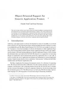
The general approach of object-oriented programming is to define a collection of classes. Once these classes are defined, instances of objects for the specific problem are created, and operations are invoked to perform the processing. The essence of object-oriented design is finding the most suitable classes for the problem. The major strength of OOP is inheritance. This is a language facility for defining new classes of objects as an extension of previously defined ones. The new class inherits the variables and operations of the previous ones. Inheritance supports code sharing by allowing the language, rather than the programmer, to reuse code from one class to another related class. For example, an Account class could be declared and two more classes, namely Deposit_Account and Current_Account could be derived from it. These two are more specialised accounts and have additional properties. However they both inherit the properties of the Account class. The class Account is called their base class or superclass while Current_Account and Deposit_Account are derived classes or subclasses of Account. The class hierarchy for the above example is illustrated in figure 2.3.
(
Account
]
Deposit
Figure 2.3: An example of inheritance
30
2. Concurrent Object Oriented Programming
Two notions of inheritance exist: •
subclass inheritance
•
subtype inheritance
Subclassing is a sharing mechanism that permits code and representation to be inherited. Subtyping is stricter than subclassing since it guarantees that an instance of a subtype can always be used in place of a supertype. Smalltalk [GoRo 83] supports the notion of subclass inheritance; Eiffel [Meye 88] and C++ [Stro 87] are based on subtyping. The above mentioned example is an instance of single inheritance. Single inheritance systems require that classes are organised in a tree structure. Many alternatives based on multiple inheritance have been proposed and implemented in languages like Eiffel. Such a mechanism has also been added to the Smalltalk language [Boln 82]. Classes are organised as a graph in systems that employ multiple inheritance. Unfortunately, the benefits of multiple inheritance are often outweighed by the complexity required to resolve ambiguities in variable and operation name conflicts [Thom 88]. The main features of C++, which was used for the purpose of this project, will be described briefly.
The C++ Programming Language C++ [Stro 87] is an object-oriented extension to the C programming Language [KeRi 78]. The main features of C++ will be described here. The discussion focuses mainly on these features of C++ that were heavily used in the implementation phase of the project. An extensive presentation of the C++ language is given in [Stro 87] and [DeSt 89].
31
2. Concurrent Object Oriented Programming
The key concept in C++, as in all 0 0 languages, is class. Classes in C++ provide data hiding, guaranteed initialisation of data, implicit type conversion for userdefined
types,
dynamic
typing,
user-controlled
memory
management
and
mechanisms for overloading operators. C++ provides much better facilities for type checking and expressing modularity than C does. A class consists of two parts, a private part and a public part. The members of both parts may be either variables or functions. The public members are directly accessible by the user of the class while the private ones may only be accessed by member functions. Several advantages are obtained by restricting access to a data structure to an explicitly declared set of functions and they are discussed in page 136 of [Stro 87]. The class is a substantial extension of the notion of a structure. In fact, structure is defined as a class without any access restrictions (i.e. all members public). However, the member functions are not the only ones who are granted access to the private members of a class. A class may identify a non-member function or another class as friend and this function or class may, then, access its private members. Each class can provide a constructor and a destructor function. These functions deal with the proper initialisation and cleanup, respectively, of the objects of that class. The names of these functions are the same as the name of the class, however the destructor's name is prefixed by a
symbol. For example, the constructor and
destructor functions of class matrix, would be: matrix: .-matrix () ; matrix: :-matrix () ;
respectively. The '::' resolution operation is used in C++ declarations of class members. However, within the context of the class a member may be referenced simply by its name. The object's constructor is automatically called upon creation while the destructor handles cleanup of the object as soon as it gets out of scope.
32
2. Concurrent Object Oriented Programming
Function names may be overloaded if the same function needs to operate on different types of objects. That means that the same function can be defined in several different ways, provided that the corresponding signatures are different. Consequently, constructors can be overloaded if an object needs to be initialised in several different ways. For example, an object of type 4 stack_ofJnt' may be created with no arguments or it may be created to initially contain a user-supplied argument. In such a case the user should supply two different constructors, namely : stack_of__int: : stack__of_int () stack_of__int: : stack_of_int (int)
However, the destructor may not be overloaded. That is because while one would possibly wish to construct an object in multiple ways, once the object has been constructed there need only be one way of destroying it. A pointer to the object for which a member function is invoked constitutes a hidden argument to the function. The implicit argument is referred to as t h i s . In every function of a class x, a pointer t h i s is implicitly declared as: x* this
and initialised to point to the object for which the member function is invoked. Since t h i s is a keyword it cannot be explicitly declared. C++ supports single inheritance (multiple inheritance has been announced for future versions [Meye 88]). A class may be derived from another class and, thus, inherit the variables and functions that the other class supports. The class is then said to be derived from the first one which is designated as its base class. The base class can be declared to be either public or private to the class derived from it. If it is declared to be public, the member functions of the base class become public to the derived class and hence are accessible by its users. If, however, the base class is declared private, its public members become private members of the derived class and, hence, may only be accessed by the member functions of the derived class and not by its users. In either case, the private members of the base
33
2. Concurrent Object Oriented Programming
class may only be accessed by its own public members. There is, however, a third case. A class may be declared to have a private base class and explicitly declare some of the base class' public members to also be public to the derived class. In that case, the users of the derived class have access to its public members and to the, explicitly declared public, members of the base class. All the other public member functions of the base class would be inaccessible to the user. Almost contemporaneously with C++, another extension of C was developed, namely Concurrent C [GeRo 86]. Concurrent C provides facilities for declaring and creating processes, process synchronisation and interaction, process termination and abortion, priority specification and waiting for multiple events, amongst other t features. Merging C++ and Concurrent C resulted in a concurrent object-oriented language
called
Concurrent
C++
[GeRo
88]. If an abstraction
cannot
be
implemented purely as a class, then a process is required. Data abstraction and parallel programming facilities are orthogonal. The syntax for the concurrent programming facilities is similar in spirit to the class syntax. Eventually, the class facility is planned to be extended to complete integration of the two languages.
2.2.2
Concurrent object-oriented models
Languages
for concurrent
object oriented programming
should provide the
appropriate constructs for expressing the designer's intuitions about the behaviour of the components as directly as possible. Moreover they should be capable of expressing finer algorithmic detail. Furthermore, in a concurrent object-oriented
system, every object will run
concurrendy with others. Thus for single processor execution frequent context switching is inevitable. For that reason architectural support for efficient context switching is indispensable. The ultimate solution, however, lies in the parallel execution of a concurrent program in a parallel/distributed architecture. The characteristics of the object (namely being self-contained and having a unified communication protocol) show that the object oriented model naturally fits in a 34
2. Concurrent Object Oriented Programming
distributed system consisting of a set of processor-memory pairs interconnected by a communication subsystem. Object-based concurrent programming languages equipped with real time features are suitable for writing programs in various application domains such as office information systems, factory information systems, music synthesis, etc. However, a major application area is Distributed Artificial Intelligence which is concerned with the cooperative problem solving by a decentralised and loosely-coupled collection of knowledge resources. Several models of concurrent object-oriented language systems exist. Two of them, namely ConcurrentSmalltalkfYoTo 86] and the Actor model [AgHe 86], will be outlined.
ConcurrentSmalltalk Concurrents mall talk is an extension of the Smalltalk language [GoRo 83]. Smalltalk is a programming language entirely expressed in terms of the object-oriented model. Everything in the Smalltalk system is an object and all computation is expressed in terms of message sending. However, Smalltalk has limited support for concurrency. It supports processes
and semaphores
as primitive types and some other
conventional IPC and protection mechanisms are implemented in terms of these primitives. However the processor scheduler implements a naive non-pre-emptive (cooperative) scheduler which results in the support for potential concurrency being limited. ConcurrentSmalltalk [YoTo 86][HoWo 88] adds asynchronous message sending to the synchronous one already present in Smalltalk. Using the asynchronous method calls, sender and receiver objects can run concurrently. ConcurrentSmalltalk also introduces new types of objects (atomic objects). An atomic object can only be accessed by one process at a time. Messages sent to such an object are executed one at a time in a FIFO manner with a single context created for each activation. 35
2. Concurrent Object Oriented Programming
ConcurrentSmaUtalk utilises all the functions of Smalltalk-80. Users can model problems which contain concurrency by using the concurrent programming facilities it provides. The compatibility with Smalltalk-80 provides the Smalltalk-80 users with concurrent programming facilities as a natural extension.
The Actor model The actor model [AgHe 86] has grown in the last decade along with other models based on Petri Nets, the λ-calculus and CSP. The actor approach tries to model a problem as a society of cooperating individuals. The capabilities needed for such an approach [Lieb 86] are the following: •
knowledge must be distributed among the members of the society each member should be able to communicate with other members of the society members of the society must be able to pursue different tasks in parallel different subgroups of a society must be able to share common knowledge and resources
In the actor model there is only one kind of object: the actor. Everything is represented by actors. The behaviour of an actor system is represented by events. An event happens when an actor receives a message. The actor abstraction has been developed to exploit message passing as a basis for concurrent computation. Essentially, an actor is a computational agent which carries out its actions in response to processing a message. The actions it may perform are: •
send messages to itself or other actors
•
create more actors specify the replacement behaviour (as described below)
36
2. Concurrent Object Oriented Programming
In order to send a message the actor needs a mail address, called the target. All actors have their own (unique) mail addresses which may be transmitted to other actors just as any other value. Thus, mail addresses, provide a mechanism for dynamic reconfigurability of an actor system. When an actor accepts a message it performs the actions specified by its behaviour. To make use of an actor, the user just has to know what messages the actor responds to and how the actor responds to each message. Relying on actors and message passing makes systems very extensible. In an actor system the user can always add a new actor with the same message passing behaviour, but perhaps with different internal implementation and the actor will appear identical to the old one as far as all the users are concerned. The system can also be extended by introducing an actor whose behaviour is a superset of the behaviour of the old actor. It could respond to several new messages as long as it responded to all the messages that the previous actor did. For parallel computations, actors called futures create concurrency by dynamically allocating
processing
resources. Another
type of
object, serialisers
restrict
concurrency by constraining the order in which events take place. Actor systems frequently use delegation [Lieb 86] as an alternative to the classinstance mechanism. Each actor, while having its own functionality, knows of other actors (proxies) to which it can delegate a message when it is not able to process it itself. A proxy may either service the message or pass it to another proxy. In this way, the previously mentioned replacement behaviour of an actor is defined. The idea of prototypical objects is often used in systems which employ delegation such as Act 1 [Lieb 86]. A new actor is created by cloning an existing actor in the system. The old actor becomes the new one's proxy. The new actor has the same functionality as the old one but new functionality can be added later.
37
2. Concurrent Object Oriented Programming
Actor systems have many advantages in parallel object-oriented systems. The delegation mechanism increases the number of potential actions which may be performed concurrendy as actors are linked only by cause and effect. An actor language provides a suitable basis for large-scale concurrency. Besides the ability to distribute the work required in the course of a computation, actor systems can be composed simply by passing messages between them. The internal workings of an actor system are not available to any other system.
A
thorough
discussion
of
several
approaches
in object-oriented
concurrent
programming can be found in [YoTo 86a].
38
Chapter 3 The European Declarative System Project
The European Declarative System (EDS) project [EDS 88] is a large collaboration principally
between
three major computer manufacturers: Siemens of West
Germany, Bull of France and ICL of UK. The primary aim of this project is to benefit from the considerable knowledge which the partners in this project have in implementing functional, logical and relational systems. The languages selected for implementation are Lisp, Prolog, ML for artificial intelligence Knowledge-based
and Extended SQL (ESQL) for database
applications
require
the
use of
big rule
applications.
sets, inference
mechanisms, functional evaluations and access to databases. Each of the languages that the EDS machine will support has a specific strength in these areas. The combination of these languages will be supported in order to exploit this strength in the most profitable way. The computational models underlying
these languages, their
implementation
strategies and their approach to parallel computation will also be supported.
39
3. THE EUROPEAN DECLARATIVE SYSTEM PROJECT
This chapter provides a general introduction to the EDS project. The approach to an architectural design of the EDS machine is presented in section 3.1. The rest of the chapter deals with the problems particular to the nature of the project. The reasons for the existence of a common intermediate layer and a definition of this common layer are presented.
3.1
The EDS machine
During the last decade, the increase in scale and decrease in cost of integrated circuit components have lead to many advances in computer design. With the advent of knowledge-based systems, users will require performance even greater than what current mainframe computers can provide. However, technology advances alone will not provide the level of performance improvement required and all recent high performance systems have incorporated architectural innovations aimed at further performance improvements. An obvious solution to the performance needs is to use a large number of cheap VLSI processors which can act as a homogeneous computing engine. The processors will need to communicate in order to cooperate, thus high bandwidth communications needs to be provided between them. The first major experiments in this area were conducted over twenty years ago. They have been repeated many times since then with very similar results; it has proved impossible to exploit the hardware potential of the machine beyond a very small number of parallel processors. The main problem has been that of dynamic variation. Programs cannot easily be partitioned statically into separate communicating serial sections, hence load balancing issues need to be taken into account. To achieve efficiency it is necessary
40
3. THE EUROPEAN DECLARATIVE SYSTEM PROJECT
to make use of both the dynamic allocation of resources and the dynamic division of a problem into appropriately sized parallel sections. Such an approach has been followed in the Flagship project [WSWW 87] The EDS machine is going to be built on the results of projects like Flagship. The output of the project is intended to be a single hardware and software homogeneous distributed
system. This product
will be ready for a subsequent
product
development cycle.
3.1.1
The Flagship project
Most conventional computer systems have been based on the von Neumann model of computation. The same model has been followed by most modern programming languages [Back 78]. There are, however, certain major disadvantages in this model. The bus linking the processor to the memory (widely known as the von Neumann
''bottleneck")
imposes
a
sequential,
word-at-a-time
approach
to
programming. Moreover, since the underlying model of computation is inherently sequential it is very difficult to improve execution efficiency by employing parallel computation. On the other hand, declarative languages are more concise and expressive, easier to program and since they do not require a precise evaluation order parallel evaluation is possible [Darl 87]. At the same time, being based on mathematical formalisms, programs written in those languages, are inherently mathematically tractable. The Flagship project aimed to build a declarative system. One major objective was to produce a parallel machine whose computing power can be increased simply by the addition of hardware resources. It was developed as a synthesis of dataflow and reduction principles [WaWW 86]. The dataflow machine which mostly influenced the design of Flagship was the Manchester Dataflow Machine [GuKW 85].
41
3. THE EUROPEAN DECLARATIVE SYSTEM PROJECT
Dataflow is a technique for specifying computations in a two dimensional graphical form: instructions that are available for concurrent execution are written alongside one another and instructions that must be executed in sequence are written one under the other. Data dependencies between individual instructions are indicated by directed arcs. Instructions do not reference memory since the data-dependence arcs allow data to be transmitted directly from generating instruction to subsequent instruction. The Manchester project has designed a powerful dataflow processing engine based on dynamic tagging. Details on the architecture of this system are given in [GuKW 85]. The reduction model of computation for functional languages [Peyt 87] can be summarised as follows: A functional program has a natural representation as a tree (or more generally, a graph). Executing a functional program consists of evaluating (reducing) an expression. The evaluation proceeds by means of a sequence of simple steps called reductions. Each reduction performs a local transformation to the graph. •
These reductions may take place in a variety of orders since they cannot interfere with each other. Thus, parallelism may be achieved.
•
Evaluation is complete only when there are no further reducible expressions.
The process is therefore one of applying functions to arguments according to a set of reduction rules. Rewriting a portion of the graph with the result of evaluating that portion is called a graph reduction or rewrite. A practical machine would regard these rewrites as the fundamental units of computation and an appropriate physical representation of the graph must be
42
3. THE EUROPEAN DECLARATIVE SYSTEM PROJECT
chosen. The computational graph is therefore represented as 'packets', where a packet is a fine-grained function together with the arguments to which it is applied or a constructor function indicating a piece of data in minimal form. Medium sized rewrites were employed for the Flagship machine, so that the highest possible parallelism could be achieved. An extensible machine structure should allow parallelism in both processing and store access if total computing power was to be increased by the addition of extra hardware. The machine structure implemented was the one illustrated in figure 3.1 The intention was that the majority of store-processor interactions will be between a processor and its local store. However it is inevitable that some interactions will have to be non-local. Access to a non-local store is achieved by sending a request message to the processor coupled to that store. Each processor simplifies the reducible sub-graphs contained in its own local store.
Figure 3.1: The Flagship closely coupled structure
The computational graph is distributed dynamically among the processors as evaluation proceeds. Details of load balancing on the Flagship machine can be found in [Sarg 87]. A prototype Flagship machine has been built at ICL, West Gorton. It consists of sixteen Motorola 68020 processor boards, each with several megabytes of store.
43
3. THE EUROPEAN DECLARATIVE SYSTEM PROJECT
Studies done on the Flagship prototype machine show that run-time performance is less than was anticipated from simulation results [Wats 88]. The reasons seem to be: •
the medium granularity of the rewrites
•
the overhead of the scheduling requirements imposed by the system software.
The EDS machine will be based on the results of projects such as the Flagship project. The proposed solution to the Flagship problems is to move to larger grained rewrites. Work is also planned to investigate ways to reduce the absolute cost of scheduling. A problem with increasing the granularity is that some potential parallelism is likely to be lost. However this LArge Grain (E) Rewriting (LAGER) model of computation [Wats 89] aims to make all potential parallelism available at run-time and to gain performance either by combining serial parts of computation into single larger grain parts, or by dynamically combining parallel parts based on information of the current load balancing of the machine. The EDS machine may be a cluster architecture where each node in the network is itself a shared store multiprocessor [Wats 89b]. Thus, the machine will be extensible in two different physical ways but the communication between the nodes may become too large for the available bandwidth. Further investigation will be carried out in this area.
3.2
The Process Control Language
In order to support the combination of the computational models underlying the languages selected to be supported by the EDS machine, an intermediate common layer will be provided [Ista 89].
44
3. THE EUROPEAN DECLARATIVE SYSTEM PROJECT
Two approaches have been considered for the intermediate common layer: •
the definition of a single intermediate language
•
a common framework which permits the integration and combination of the different computational models
However,
experience
with
three implementations
of the LYNX
distributed
programming language has shown among others that from the point of view of the language implementor, the ideal operating system probably lies at one of two extremes: either providing everything that a language needs or providing nothing, but in a flexible and efficient form [Scot 86]. A kernel that provides some, but not all, of what the language needs is likely to be both awkward and slow. Awkward because it has sacrificed the flexibility of the more primitive system, slow because it has sacrificed its simplicity. Therefore, since the EDS machine is going to support a variety of programming languages the first approach would not be efficient enough for all of them. A common framework allows the most benefit from the individual computational models. The goals of the project can be satisfied by the ability to communicate with the different language systems, the ability to switch to another language system and the ability to execute all provided languages efficiently. Thus, the second approach will be followed. The issues of the PCL and its associated execution mechanisms are: •
process management
•
access to shared data
•
memory allocation and management
•
addressing schemes
•
canonical data representation for interfacing
•
load balancing and locality issues 45
3. THE EUROPEAN DECLARATIVE SYSTEM PROJECT
A major design decision with regard to this intermediate layer derives from the fact that in all of the considered models program units can be identified, which can be executed sequentially. These units can be described as processes and in fact they will be realised as lightweight processes (also called threads). The use of sequential processes provides many advantages: they are a natural target for many languages •
they can be used for efficient sequential optimisations and they can be adapted to different processing grain sizes
Therefore, the name Process Control Language (PCL) was chosen for the common framework which will handle the common issues of, parallel computation of the various language systems. PCL will be implemented as an embedded language in the form of system calls or calls to the run-time system itself. Each language system will generate calls to the PCL run-time system itself. The major design issues for PCL concern the process modeU the store model and the communication modeL These models will be discussed in the remainder of this section.
3.2.1
The Process Model
The PCL defines a process model for a system structure with distributed memory organisation and a high speed interconnection network. The PCL is a common interface between the language systems and the EDS hardware. The functional requirements include process management similar to conventional operating system kernels. The PCL kernel will also implement functions that extend the conventional mechanisms to the distributed machine architecture. This includes the proposed message passing scheme, the concept of lightweight processes and the agreed store model.
46
3. THE EUROPEAN DECLARATIVE SYSTEM PROJECT
Conventional operating systems provide a single abstraction for resource allocation and scheduling, variously known as a process, task or virtual machine. Creation, scheduling and deletion of such entities is expensive in terms of time and space consumption because a lot of contextual information is involved (memory space, IPC channels, stack, etc.) Also, as only a single flow of control is allowed, it is difficult to program multi-threading applications. The approach of PCL separates the control-flow and machine-state information from the rest of the context data. Two entities are defined: the thread, representing a single control flow and the task representing the unit of resource allocation. A thread is the basic unit of (sequential) computation (the basic unit of CPU allocation), i.e. it is assigned to exactly one Processing Element (PE). A task is an execution environment and the basic unit of resource allocation (store etc., but not CPU). The resources can be allocated dynamically to a task.
Figure 3.2: PCL Mapping of tasks and threads to Processing Elements Tasks provide the mechanisms for heavyweight processes (like UNIX processes) while threads realise lightweight processes. A UNIX process is equivalent to a task with one thread.
47
3. THE EUROPEAN DECLARATIVE SYSTEM PROJECT
More than one thread may run in the execution environment of a task. One thread is created for each task automatically when the task is created. The execution environment of a task may be spread over several PEs without physically shared memory. Thus, different threads may execute concurrently on different PEs but in the same context. The mapping between threads, tasks and PEs is illustrated in figure 3.2
3.2.2
The Store Model
On the EDS machine a virtually shared memory is provided to each task. This address space is common to all the task's threads. The address space of a task is divided into segments and pages in the usual and well-established way. The abstraction of virtually shared memory offers a simple view of the system to higher levels of software, like applications or run-time systems of programming languages. For example it allows passing of non-local references - e.g. to parameters or execution environments - between threads of the same task running on different PEs. This is very useful in situations where it cannot be determined in advance which parts of an environment will be needed by some other thread. As a task may spread its threads over different PEs which do not have physically shared memory, the shared address space must be mapped to different PEs in a distributed fashion.
3.2.3
The Communication Model
Apart from tasks and threads, PCL also provides a third kind of object, the port. Ports provide a mechanism for communication between threads in one task or in different tasks. A port is a buffer in which messages may be sent and logically queued until reception. It is implemented as a message queue managed by the PCL kernel. The
48
3. THE EUROPEAN DECLARATIVE SYSTEM PROJECT
port's message buffer is allocated in the local memory of its owner thread. Only this thread is allowed to read messages from this port. Upon creation of a thread an initial communication port is created which is owned by the newly created thread. The initial port of the task's initial thread is the task's system port that may be used to send signals and software interrupts. Communication between threads of one task can be achieved by virtually shared memory with several modes of sharing (cached with/without update, not cached) or by explicit message passing via communication ports. For threads in different tasks communication is achieved by message passing or by explicitly shared memory. PCL provides both asynchronous and synchronous IPC using a fairly conventional set of message passing primitives. Additionally, when sending messages, the sender can specify whether store coherency is needed (on the sender's store) before the message is sent. It is a design aim to use hardware assistance to provide an efficient message passing system
Parallelism may be used on the thread level by a task which has threads on many different PEs all sharing a coherent view to the same virtual address space. It may also be used on the task level by several sequential tasks which communicate by message passing between separate address spaces. It is expected [Ista 89] that adopting the principles outlined above will provide the opportunity to develop an extensible, high-performance, parallel system based on: •
a tightly-coupled network of processing nodes, each with local store
•
a distributed task with truly concurrent threads
•
a hardware-assisted store coherency mechanism
•
hardware-assisted message passing
49
3. THE EUROPEAN DECLARATIVE SYSTEM PROJECT
3.3
A proposal for a PCL simulator
At the time of writing, an implementation of a PCL simulator is under development by the Software Environments group of the Computer Science Department in the University of Manchester. This implementation is being done in the object-oriented language C++ on top of the Chorus distributed operating system [Prio 89]. Chorus was a research project on Distributed Systems at INRIA in France from 1979 to 1986 [Rozi 88]. In order to understand how a mapping from PCL to Chorus can be achieved, a brief description of the Chorus concepts and architecture will be presented.
3.3.1
The Chorus Distributed Operating System
A Chorus [Rozi 88] system is composed of a small-sized nucleus and a number of system servers.
Subsyst. 1 Interface Subsystem 1
P2
Q2
R2
Lib.
Lib.
Lib.
Application Programs
Subsyst. 2 Interface
System Servers &
Subsystem 2 Libraries
CHORUS Nucleus Interface CHORUS Nucleus
Generic Nucleus
Figure 3.3: The Chorus Architecture
50
3. THE EUROPEAN DECLARATIVE SYSTEM PROJECT
These servers cooperate in the context of subsystems (e.g. UNIX, PCL) providing a coherent set of services and interfaces to their users. The Chorus architecture is illustrated in figure 3.3 The overall organisation is a logical view of an open operating system. It can be mapped onto a centralised as well as on a distributed configuration. The Chorus Nucleus has not been built as the core of a specific operating system, rather it provides generic tools to support a variety of host subsystems, which can co-exist on top of the Nucleus. The basic abstractions implemented and managed by the Chorus Nucleus are: Actor: the unit of resource collection and memory address space. An actor encapsulates a set of resources, namely: - a virtual memory context divided into regions, coupled with local or distant segments, - a communication context, composed of a set of ports, - a processing context, composed of a set of threads •
Thread: the unit of sequential execution. It corresponds to the usual notion of a process. A thread is tied to one and only one actor, sharing the actor's resources with the other threads of the actor Port: the unit of addressing. Ports can be grouped dynamically into Port Groups providing multicast or functional addressing facilities
•
Message: the unit of communication. Messages are addressed to ports Unique Identifier: a global name. Ports, Port Groups and Actors are all assigned Unique Identifiers (UIs) upon creation
•
Region: the unit of structuring of an Actor's address space
51
3. THE EUROPEAN DECLARATIVE SYSTEM PROJECT
Segment: the unit of data encapsulation. Segments are collections of data located anywhere in the system and referred to independently of the type of device used to store them •
Capability: the unit of data access control. Resources can be identified within their servers by a key which is server dependent. Since keys have no meaning outside the server they are associated with the port UI to form a global Capability Protection Identifier: the unit of authentication. Actors and threads receive protection identifiers with which the nuclei stamp all the messages they send and which receiving actors use for authentication.
Upon creation of an actor, a port is attached to it allowing that actor to receive messages on that port. Later, more ports may be created by explicit use of the port creation call. Each port is attached to the actor which created it. Ports can migrate from one actor to another. Any thread knowing a port can send messages to it. Within an actor, ports and threads are named (in system calls) by local contextual identifiers (LI). The physical support of a Chorus system is composed of an ensemble of sites interconnected by a communication network. A site is a grouping of tightly-coupled physical resources. There is one chorus nucleus per site. A given site may support many simultaneous actors. However, actors (and threads) can not migrate from one site to another. Threads communicate and synchronise by exchanging messages using the Chorus IPC even if they are located on the same site. Messages are not addressed directly to threads (nor actors), but to ports. A port represents both: •
a resource (essentially a message queue)
•
an address to which messages can be sent
52
3. THE EUROPEAN DECLARATIVE SYSTEM PROJECT
The chorus IPC permits threads to exchange messages in either asynchronous or synchronous (RPC) mode. RPC guarantees that the response received
by a client
is definitely that of the server and corresponds effectively to the request. In the asynchronous mode, though, the system does not guarantee that the message has been actually received by the destination port nor site. Asynchronous IPC is basic enough to allow building more sophisticated protocols within subsystems and reduces network traffic in the successful cases. The main Chorus abstractions may be visualised as illustrated in figure 3.4
Figure 3.4: Chorus main abstractions
The foundation of the Chorus architecture is a generic nucleus running on each machine; communication and distribution are managed at the lowest level by the Nucleus. The Chorus system has been implemented mainly in C++. The abstractions provided by Chorus correspond to object classes which are private to the Chorus
53
3. THE EUROPEAN DECLARATIVE SYSTEM PROJECT
nucleus. Both the object representation and operations on the objects are managed by the Nucleus. Chorus have written the bulk of their current system using C++ to provide an objectoriented framework. The system design being proposed is based upon an objectoriented design style where the system is viewed as a decomposition of data, rather than a procedural approach.
3-3.2
The Mapping of PCL to Chorus
The first implementation of a PCL simulator will be provided on the Chorus system running as a bootstrap kernel on a SUN 3 workstation. Despite the differences between PCL and Chorus, the two systems appear to be quite similar in some sense. The mapping of the four fundamental concepts of PCL to those of CHORUS can be described as follows. •
Tasks: PCL supports a distributed task across many PEs. The Chorus actor is bound to a single site. A distributed task may, thus, be modelled by multiple actor instances.
•
Threads: there may be a simple one-to-one mapping from PCL to Chorus threads since they are both locked onto a particular site.
•
Ports: PCL ports are owned by threads whereas Chorus ports are owned by
actors.
However,
this
ownership
may
be
hidden
from
the
communication primitives. •
Memory Allocation: User address space is defined in terms of logical regions which map onto segments. PCL has fixed sized segments partitioned into fixed-sized pages. Chorus provides regions, segments and pages with segments served by special servers called mappers.
54
3. THE EUROPEAN DECLARATIVE SYSTEM PROJECT
The Chorus kernel manages basic system resources - store, processor allocation and IPC. These management operations are available in the Chorus kernel interface. A subsystem may be built on top of the Chorus kernel to implement its own process semantics [Prio 89]. This subsystem provides, as its upper interface, some particular set of primitives, supported at its lower interface by the primitives of the Chorus kernel. PCL may be implemented as such a Chorus subsystem, providing thereby the PCL primitives built on the underlying Chorus kernel. Further work will then be undertaken to port Chorus onto the Flagship prototype machine in order for a full parallel version of the PCL simulator to be tested.
55
Chapter 4 Support Environments and Tools
The term ''software engineering" was first introduced in 1968 at a NATO Science Committee conference set up to examine the problems of developing software [NaRa 68]. Progress has been made in the field since then, masked to some extend by the increasingly complex products the industry has been expected to produce. Some of these improvements are: better methods of project control and quality management, development of the life-cycle model, the evolution of formal and structured methods and, most interestingly, the development of automated tools to support these techniques. Support systems for the software development have been developed to manage the complexity of the development of large software systems, to reduce the problems in exchanging objects between different tools and to make the software development process more efficient and productive. On the side of programming languages, Fourth Generation Languages (4GL) have evolved which provide an alternative approach to the design and development of information systems.
56
4. Support Environments and Tools
This chapter discusses the usefulness of support environments and 4GL in general and introduces the EDS Development Route (DR) environment and the Base Model language that it incorporates.
4.1
Fourth Generation Languages
The, so called, fourth generation languages (4GL) are complete
programming
systems, not merely programming languages. However they do fit into the same general trends as the others since they concentrate on: •
increasing conciseness, clarity, and expressive power
•
more emphasis on declarative features, i.e. specifying what has to be done rather than the fine detail of how the machine should go about and doing it.
4GL were developed as a result [Wils 88] of the dissatisfaction of business users with large conventional languages such as COBOL. These users were often not professional programmers but wished to obtain quick results from data stored in a computer. The characteristics of an ''ideal" 4GL [Sarg 89] are the following: Everything is built around a database whose DataBase Management System (DBMS) hides implementation details of data structures, file structures etc. •
They provide a query language allowing fast, ad-hoc queries
•
They
provide
a high-level
declarative
language
for fast, on-line
programming of process logic •
They support rapid prototyping - working parts of the system are produced quickly at an early stage
57
4. Support Environments and Tools
Many parts of the process are automated, e.g. system documentation, generators for forms and reports etc. •
Automatic maintenance of consistency over the whole project through an automatic, active, integrated data dictionary
•
User-friendly Human Computer Interfaces with graphical tools to help produce Data Flow Diagrams (DFDs), entity models etc. which are translated directly into prototype database design and code They have built-in standard applications like graphics statistics, and financial modelling
•
They are highly portable
The 4GL systems currently in use tend to have some, but not all, of these features.
4.2
Support Environments and Tools
In an industry that is rapidly expanding and with hardware prices continuously falling, Software Engineers are being required to keep production delays and costs to a minimum, while software produced becomes increasingly complex. One of the big problems in system development is the need to develop systems flexibly and economically. People involved in the process of developing an information system are assisted by the provision of working environments appropriate to the tasks at hand. In a complex and challenging activity such as the development of information systems, the use of computer tools to carry out certain tasks, is absolutely necessary One important problem in automating the software development process is the provision of an environment for developing software systems. In a sense,
58
4. Support Environments and Tools
environments have evolved in concert with the software engineering community's understanding of the tasks involved in the development of software systems. From an historical perspective, we can see a trend which started with the integration of a compiler, an editor and a debugger into a programming support environment.
The next
step was the integration
of design
tools, version
management capabilities, documentation support etc. into what is known as software development environments. The next step in this direction is represented by the now emerging IPSEs (Integrated Project Support Environments) that intend to provide coverage for a whole project. UNIX may be viewed as an IPSE since it provides: Many tools, e.g. YACC (parser generator), sort program, spelling checker •
Software version control (Make, SCCS) General mechanisms for combining programs together, such as pipes and filters Support for working over distributed machine, e.g. NFS, Yellow Pages
However, all the above are not actually integrated into a concrete support environment In
general,
for each
phase
of
the
software development
process
several
methodologies exist which, more or less, fit in the domain of the application. For each phase one or more tools can be used depending on the chosen method, the development language or the target machine. This leads to software fragmentation [GDRH 89]. There must be tools to support each phase. They must be integrated together in order to manipulate heterogeneous data in a cohesive support environment The tools which are used can be separated into global and local tools [HoSS 89]. Global tools serve in the project management and administration. Local tools serve in software engineering, in the different phases of the software life cycle (analysis, design, implementation, etc.) or the local administration. In order to 59
4. Support Environments and Tools
realise a software support environment the local and global tools have to be integrated into one environment.
4.2.1
The CADES System
The notion of support environments is not new. In the early 1970's ICL developed the CADES system [Warb 89a] as a support environment for the development of the ICL Mainframe Operating System VME (Virtual Machine Environment) [Warb
80].
Since
then, the
CADES
system
has
been
used
continuously
accumulating on the way the outputs of some 3000 man years of endeavour over 16 years. CADES was a support environment which supported all stages of the operating system
development
process,
i.e. high
level design, low
level design of
implementation, construction, system generation and maintenance. The emphasis was on the modular structure of the system being designed to manipulate defined data items. Each code entity was termed a ho/on. A language called
SDL (System Development
Language)
was developed
to allow the
expression of the relationships existing within the system. The hierarchy of SDL holons represents a gradual refinement of the total description of the system at that level of design, the level being fixed by the accompanying data tree decomposition. At the lowest levels, this use of SDL merged into the implementation language S3. The CADES database was setup to record information about the various relationships of the system. This was then used as the basis for version control and other management support purposes. The approach taken in the CADES system was product structure derived. It was an approach of "Design and Evaluate". However it was a closed system. It was closed in the sense that any tool added to the system was constrained by the core style of schema representation. New tools had to be totally integrated and the resultant costs severely restricted the ability to experiment with new toolsets.
60
4. Support Environments and Tools
4.2.2
The IPSE.2.5 Project
The IPSE 2.5 project [Warb 89b] [Snow 89] is being carried out under the UK Alvey Programme Software Engineering Strategy. Its name is due direcdy to the identification in the Alvey programme of three generations of the so called Integrated Project Support Environment - IPSE 1, IPSE 2, IPSE 3. The IPSE 2.5 project lies somewhere between the second generation, characterised by the use of databases and the third generation, characterised by the use of artificial intelligence techniques. An IPSE is a computer based system supporting the technical development and maintenance of an information system. Specifically IPSE 2.5 is a project whose objective is to develop a small number of IPSEs each constructed on the basis of particular characteristics. The characteristics which are of principal interest to the project are concerned with advancing beyond current IPSE projects in two important areas: Process Modelling: This is concerned with the need to provide support for the many processes involved in the production of computer systems. Formal
Methods:
These
are mathematically
based
approaches to
software development. The term Process Modelling is used to describe the production of models of processes by which information systems are developed, and the use of these models in an IPSE. A key component in an IPSE 2.5 system is the Process Control Engine (PCE). The PCE can be loaded with a process model of the activities to be carried out by the staff of the project using the IPSE. The IPSE 2.5 project is developing a language in which such models are expressed. This language is called the Process Modelling Language (PML). Early work reporting on ideas contributing to this language can be found in [OuRo 87]. 61
4. Support Environments and Tools
The PCE provides appropriate working environments for the members of the project. Tools are provided in these environments for the development of the system being produced. These tools may be tools developed elsewhere or may be developed by the IPSE 2.5 project itself and be more tightly bound into the environment. Certain tools are developed to enable the use of formal methods. In fact, the project will develop an IPSE to support a combination of OBJ [GoMe 82] and MALPAS [Bram 87] formalisms. Commercially available tools for OBJ and MALPAS will be integrated within the model for the use at the appropriate points within the development process The view taken in the IPSE 2.5 project is to stand back from the position of "users and tools" and consider the problem of information systems development as a whole. The IPSE 2.5 project may be seen as a logical successor to systems such as CADES where the environment is seen as providing the components out of which the process is formed, but in a completely general way which is ignorant of process. The IPSE 2.5 project emphasises the need for an Open System in a process sense and in terms of flexibility of tool interworking. It intends to provide a framework that will support system development "in the large" and for component reuse of a wide variety of component types.
4.23
The Flagship Support Environment
The Flagship project was motivated by the desire to build a novel parallel machine for the support of functional languages. Consequently, graph reduction, the most efficient model for the parallel evaluation of functional languages programs, was chosen as the core computational model of the system.
62
4. Support Environments and Tools
The Software Environments Group of the Computer Science Department in the University of Manchester developed an approach to the production of the Flagship Software System, based on the computational model of a fine grain packet-based graph rewrite architecture. The Flagship Software Development Route provided an environment (in the sense outlined in the beginning of section 4.2) for the development of the Flagship Software
Environment.
The
Flagship
system
software was
constructed
as
instances of Abstract Data Types (ADTs). Each ADT instance has a number of operations
and
an encapsulated
state.
Several
operations
may
be invoked
concurrently. A variety of tools have been designed for the Flagship software development process. Each software developer has a work area in which to develop and store ADTs. The ADTs, which are specified in a combination of VDM [Jone 86] and Hope4* [Perr 88], are
processed
by
the
SPADE
(Specification
Processing
And
Dependency
Extraction) front-end processor [Bodd 1988] into an intermediate specification format before being registered in the Development Route (DR). When the development of the user's ADT is complete, it will be transferred by the System Administrator from the User Area into a Product Area. From the data store within the Product Area, it will be possible to produce documentation for the Flagship Operating System, such as Inspection Report Information and a Data Dictionary. Most of the work involving the Product Area is still to be done [Apps 89]. A DR database has been built to support development of sequential systems which enables users to develop individual ADTs from VDM specifications to Hope4" via SPADE.
63
4. Support Environments and Tools
It is strongly believed that graph reduction could be a general model of computation subsuming all concurrent languages. To show this, an already existing objectoriented language, called POOL [Amer 86], was chosen
which is different in its
concurrency mechanism and implementation from the ADT-style language which was under development and implemented by the Flagship System Software group. A compiler translating POOL to IIS (Idealised Instruction Set) was written in Hope4". The compiler's responsibility apart from straightforward translation was to extract the largest possible portions of sequential code from the source codes, leading to the maximal grained size implementation of POOL on the Flagship system [Shar 89].
4.3
The EDS Development Route Environment
Abstract Data Types (ADTs) provide an effective means of structuring sequential software systems in terms of components and interfaces. ADTs are also a useful abstraction for writing parallel programs. The notion of ADTs maps in a straightforward manner to the OO notion of classes. HYDRA [Wulf 74] was the first system to adopt an OO view to address the fact that the design of parallel systems is as much of an art as of a science. Complex software systems are too large to work on all at once. Various strategies have been devised to help designers manage this complexity by dividing the work into small steps, each small enough to be understood fully. The primitive components built in this way can be used as building blocks for constructing more complex ones, hence this approach provides a means for potential component reuse. Building complex software systems by reusing more primitive components is what the use of inheritance provides in OO program design. Software reuse dramatically reduces development time.
64
4. Support Environments and Tools
The Development Route (DR) environment [Sa 89a] of the EDS system is aimed at supporting the design and development of concurrent systems in an objectoriented style. It builds on the experience gained in developing the Flagship Development Route Environment and introduces the notions of the object-oriented paradigm. The features of object orientation described in chapter 2 provide a powerful approach to the design of parallel systems. A major concern of the DR is the problems associated with creating a close integration between the development process and the dynamic incorporation of new and modified components into an operational system. The major aims [Apps 89] of the Development Route are concerned with: •
The provision of a common framework of software tools across the project in order to support the total life cycle from Requirements Capture through Formal Specification to Implementation and System Integration The specification and development of specific methods and tools to support the development of a Kernel and Run-time environment
Software development environments have been categorised into a taxonomy [Dart 87] consisting of four types: Language-centered: which provide integrated tools supporting a specific language Structure-centered:
which
support
direct
manipulation
of
program
structures in a language-independent manner and different views of program structures at different levels of abstraction •
Toolkit environments: which consist of a collection of smaller tools which may or may not share information with one another Method-based:
which
support
specific
software
development
methodologies via computer-aided software engineering tools
65
4. Support Environments and Tools
According to that classification, UNIX (mentioned in section 4.2) may be categorised as a toolkit environment while the EDS environment is method-based. The method supported by the EDS environment is the object-oriented design method. At the heart of DR is the Base Model (BM) language [Sa 89b]. This is an objectoriented, concurrent modelling language which provides compositionality. Base Model is following the object-oriented paradigm by building systems in terms of ADTs. These ADTs can be composed to form new ones which will integrate the facilities provided by their subcomponents. In this way the 0 0 notion of inheritance is incorporated in BM. The DR may be seen as comprising two parts. These two parts are separated by the vertical dotted line in figure 4.1. The first part of DR (the one at the left of the dotted line) is concerned with the development of an application system. The route followed is the one indicated by the arrows. Users should first of all create a BM program of the application. Then, the resulting program may be further developed in either top-down or bottom-up approaches by refining, abstracting and composing its subcomponents. At any stage, the BM program can be tested on some test obligation or interpreted. The test obligation is specified by the users. The language(s) for describing test obligations is yet to be defined. The test activities include both dynamic testing and static queries [Sa 89a]. Having created part of the application systems in BM, users can then translate the BM programs into other languages. Alien tools can be applied to the target
66
4. Support Environments and Tools
language programs. The second part of the DR is aimed at supporting the integration of alien tools.
(a)
(b)
Figure 4.1: Activities of the EDS Development Route Environment The ultimate aim is to design and implement a generic translator generator which will
generate
translators
for the chosen
target
languages.
For the
initial
implementation a translator will be implemented with the object-oriented language C++ as the target language. The rest of this section will describe BM.
4.3.1
The Base Model Language
A successful approach to develop software systems is the 'components' approach. Systems are built from components. Components exist to supply
services.
67
4. Support Environments and Tools
Eventually established systems become components themselves in larger systems. New components are integrated in systems while obsolete ones are removed or replaced. Thus, the task of developing systems becomes one of integrating existing systems with new components. The term architecture [HeWa 89] is often used when discussing computer systems. The architecture of a system has two parts: •
the constraints which must be obeyed by a component to ensure that it is integrable
•
the rules of composition which ensure that when components are combined together they also form an integrable component
A variety of techniques need to be employed for the development of such systems. Therefore a generic design framework is needed. Different types of components possess different properties. For a component to possess a certain property it needs to satisfy some corresponding constraint. For example, in order to develop a serialisable concurrent system the constraint that should be applied on its components would be that all operations should be atomic. For the EDS support environment, a constraint oriented design framework is being developed. It intends to support the design and development of distributed systems. This framework provides a concurrent, object-oriented modelling language, Base Model (BM) [Sa 89b]. Using BM, a system is modelled in terms of Abstract Data Types (ADTs). The BM language provides three primitives ADTs: •
Synchronous ADT
•
Asynchronous ADT
•
Composed ADT
Each ADT defines a type. The components of a system are instances of such types and they are called objects. As mentioned before, the design framework of the EDS
68
4. Support Environments and Tools
is constraint-oriented. Each ADT satisfies some constraints. These constraints constitute the invariants of the instances (objects) of the ADT. The BM language provides compositionality. New ADTs may be constructed from the existing ones. If the new system needs to possess a certain property, its ADTs should conform to the desired constraints. Each of the Β Μ ADTs has a name, a private state and provides some operations to its users. These three constitute the stuctural aspects of the ADT. However, not all ADTs behave in the same way. Their similarities and differences will be illustrated later. The allowed computations for each ADT constitute its behavioural aspects. At any stage an operation of an ADT may call an operation of another ADT. This, however, is not always permitted for the system being constructed. For example, if a livelock free system is to be constructed, such nested operations may lead to a cycle within the system and that may lead to the undesirable situation of livelock. In order to avoid such situations, constraints are imposed which must be satisfied at all stages by the system objects. The first two ADTs, namely the synchronous and the asynchronous, are sequential processes. So, the term sequential ADT (or sequential object for an instance) will be used for either of them. The objects of both these two ADTs may use the operations provided by other objects (which constitute the ADTs usage relation). The instance names of those objects need be declared within the object. These objects constitute its formal parameters. At the time of initialisation, they are allocated real objects. A sequential object may also comprise some internal functions which are not accessible to its users. They exist for the sole use of the object itself. For example, if an object of type 'stack' were to be created, the user might be contended with two operations, namely s t a c k _ j ? u s h and s t a c k j o o p . However, the stack object itself would also need another operation to inform it of whether the stack is empty or not. This is__empty operation would be internal to the stack object.
69
4. Support Environments and Tools
The computation of an object is a sequence of operations and the computation of an operation is a sequence of events. However, the sequencing of those events differs among different ADTs. The events which model an operation of an ADT are the following: •
accept: starts an operation; the actual parameters are accepted
•
return* completes an operation; the result is returned to the caller update: changes the state of the object
If, within an operation another operation is called, this call is modelled by a pair of events: •
send: makes the request to the other operation; the actual parameters are passed to the called operation
•
receive: completes the call; the result is received from the calling operation
The composed ADT is a collection of subcomponents. These subcomponents may be of any type that BM provides. Thus the definition of a composed ADT may contain other composed ADTs within it. The composed ADT is the potential of BM for concurrency. Each composed object is a concurrent object since the objects it incorporates may execute independently of one another in parallel. The particulars of the BM primitives will be described next.
4.3.1.1
The primitive ADTs
The Synchronous ADT An instance of a synchronous ADT is called a synchronous object. In the case of a call to an operation of a synchronous object, the sequence of the events is the following: acceptj {send, receive], update, return
70
4. Support Environments and Tools
where the curly brackets are used to denote repetition (zero or more times). The state variables of an object, and the instance names of the objects it uses constitute its formal parameters. Upon creation of an object actual objects are assigned to these formal parameters. Calls to the operations of a sequential object (either synchronous or asynchronous) must be executed serially. Whenever a call to an operation occurs, the operation will have to finish before the caller may be freed.
The Asynchronous ADT The structural definition of an asynchronous ADT is the same as the synchronous ADT. However, the behavioural definition is different in the sense that the events of an operation have the following sequence: accept, return, {send, receive], update As soon as an asynchronous object accepts a request from a caller it puts it on a queue and the caller is freed. Requests from different callers are, thus, guaranteed to be serviced in the same order that they arrived but the callers are not forced to wait for the triggered operation to complete.
The Composed ADT As already mentioned, a composed ADT is basically a collection of subcomponents. An instance of a composed ADT is called a composed object. The composed ADT may be nested, in the sense that a subcomponent may be either a sequential or a composed object The names of these subcomponents are the formal parameters of the composed object. Actual composed objects are instantiated to the formal parameters when such an object is created.
71
4. Support Environments and Tools
The operations provided by a composed object are the operations provided by its subcomponents. However, the implementor might want to hide some of these operations and use them only locally to the composed object. This facility is also provided by BM. The set of objects required by a composed object is the union of the sets of objects required by its subcomponents excluding its member objects. In contrast to the objects described above, a composed object is a concurrent object. Objects within a composed objects are allowed to execute in parallel. Given two objects within a composed object the two object can execute in parallel if the following constraints are satisfied at all computation steps: one object is idling and the other is not interfering with it one object is sending a request to call an operation of the other and the other object is accepting the call
•
4.3.1.2
one object is returning a result and the other is receiving it
Developing Systems with BM
New types can be defined from the primitive BM types. Whenever a system needs to possess a certain property, the corresponding ADT will need to satisfy some constraints. The constraints are the invariants of the new type. For example, if a composed ADT satisfies the constraints that: •
no object of the system is allowed to use the operations of itself directly or
•
indirectly all objects of the system are synchronous
then this object is characterised as a Strongly Ordered Composed ADT (SOCA).
72
4. Support Environments and Tools
A SOCA system is livelock-firee. A composed ADT, which allows a cycle to be formed in the usage relations of the objects within it is called a Weakly Ordered Composed ADT (WOCA). A generic constraint of a WOCA is that a cycle is allowed only if at least one object in the cycle is an asynchronous object; otherwise livelock might occur. As an example, suppose we need to construct a system out of two synchronous objects, A and Β with operations: A.service, A.terminate B.service ordered as in figure 4.2 service
|
terminate
\\
\
>
service
Η Β
Figure 4.2: A non-deadlock free system Suppose also, that when object Β is busy servicing the service request made by object A, an error occurs. Β needs to inform A to terminate but A is busy waiting for a reply from Β and thus cannot unblock and accept the terminate message from Β. Thus a deadlock occurs. However, there is a way out of this problem. A third object (asyncjC) can be used for the only purpose of handling this case. This will need to be an asynchronous object which will provide an operation, say, interrupt. When this operation is called, since the object is asynchronous, the caller is immediately freed and then object asyncjC calls the operation terminate of A. So Β will call the operation interrupt of
73
4. Support Environments and Tools
asyncjC and then finish its work thus unblocking A. Object A will then receive the terminate call from Β via async_C and will exit. This is illustrated in figure 4.3. service
1
lermmate
interrupt f async__C
service
\
Β Figure 4.3: A livelock free system WOCA and SOCA are examples of systems which can be developed with BM. When a system which possesses a certain property needs to be developed, it can be derived from a combination of the BM primitive types by applying the appropriate constraints.
The BM language with its three primitive ADTs may be used in order to capture constraints of systems. ADTs can be used to capture certain design styles, for instance, in order to develop a system in a refinement style, an abstract composed component can be used so that the system can be described at different levels of abstraction [Sa 89c]. A more detailed presentation of the BM language can be found in [Sa 89b].
74
Chapter 5 Modelling of the Base Model Sequential ADT
5.1
Introduction
Modelling of a system's behaviour in BM can be done in two different, yet related ways. Both are based on the object-oriented model of computation but differ in the notations they incorporate in order to describe a system in Β Μ terms. They are illustrated in figure 5.1. A specification of the system can be given in terms of messages sent and received by different ADTs. This message-oriented specification of a system's behaviour can then be translated into a concrete BM representation which models the system as a collection of ADTs, each comprising a set of operations and a private state (Fig. 4.1a). These ADTs interact by procedurally calling each other's operations. This phase of BM systems translation is considered by Y. Qin [Qin 89]. This concrete BM representation of the system is not, yet, in an executable form; it needs to be translated into an executable language which will be able to support the notions of abstraction and concurrency underlying the BM model (Fig 4.1b). As mentioned in the introduction, C++, supported by the Chorus process primitives,
75
5. MODELLING OF THE BASE MODEL SEQUENTIAL ADT
provides the abstraction and concurrency necessary for the run-time support of the BM primitives. The BM translation route is illustrated in figure 5.1.
Figure 5.1: BM Translation Route Most parallel programming systems are presented in terms of a fixed set of primitives (e.g. send/receive a message) running on top of a kernel. These primitives together with a kernel define a 'model' of parallel programming that, while pleasing the implementor, may not always be satisfactory to the application programmer. This chapter presents the mechanisms devised, in order to support the translation phase (b) of the sequential primitives of a BM program and their run-time execution. These mechanisms present a natural abstraction model for the ADTs which provides the user with a procedural interface. At the same time, the run-time behaviour of the ADTs is defined in terms of messages sent and received between active objects, which execute concurrently in a shared address space.
76
5. MODELLING OF THE BASE MODEL SEQUENTIAL ADT
As mentioned in the introduction, these mechanism will be used later by the BM run-time system in order to provide concurrency support for the BM applications. Apart from the run-time system, a translator will have to be implemented eventually which will perform the mapping of a BM program to an executable form. This dissertation is not concerned with the implementation of this translator. However, it will be made clear, how the mapping from BM to C++ (and Chorus) can be done at the conceptual level. The mechanisms presented in this chapter have a generic form that will allow them to be successfully implemented in the eventual translator. The behaviour of a hand-coded example is presented at the end of the chapter. This example implements those mechanisms in order to demonstrate their use in an actual
implementation.
The
most
important
parts
from
this
example's
implementation appear in the appendix as a reference which can be consulted throughout the reading of this chapter. The object-oriented language C++ and the Chorus distributed operating system have been used for the modelling of the BM sequential objects. The C++ notion of a class together with the Chorus notion of communicating threads are the barebones of the model's architecture and, hence, central to the discussion in this chapter. The asynchronous and the synchronous ADTs are very similar. They are both sequential primitive building blocks of BM, comprising a private state which can only be accessed by the public members (operations that the ADT provides). However, by definition, they have different behaviours since they employ completely different calling mechanisms. Both their similarities and differences appear in the resulting model. This is mainly a consequence of the fact that a stepwise refinement approach was taken to their design while, at the same time, the use of the C++ inheritance mechanism allowed for maximum code sharing.
77
5. MODELLING OF THE BASE MODEL SEQUENTIAL ADT
In the remainder of this chapter the term ADT will be used
for both the
asynchronous and the synchronous one. Whenever the distinction needs to be made it will be done so explicitly.
5.2
The Model
The model derived for the BM sequential object will need to provide the concurrent behaviour that is needed and also handle the problems introduced by the distributed nature of the target system. The Chorus notion of different threads running on different PEs together with the underlying message passing scheme seem appropriate for handling these problems. Additionally the idea of structuring of the data and operations into ADTs is another feature that needs to be dealt with accordingly. The C++ class seems appropriate for expressing these features.
5.2.1
The Dynamic Behaviour
The dynamic behaviour of an ADT is modelled by a Chorus thread and two ports. A message passing scheme is employed and will be extensively discussed later. According to this scheme any invocation of an operation that an ADT provides results in the construction and dispatch of a message to the ADT's thread. One of the ports is used to receive these calls (the Input or Question port). After the message has been received a reply message is constructed by the thread and is returned to the caller. The port that this message is addressed to is the one that initially sent the request. Thus that port is designated as the 'Reply port'. The thread is responsible for polling the input port and servicing the incoming message. Servicing involves choosing the right operation code, executing it and returning the result to the caller (in the case of the synchronous ADT) or simply
78
5. MODELLING OF THE BASE MODEL SEQUENTIAL ADT
keeping the message in a queue and servicing it at a later time (in the case of the asynchronous ADT).
5.2.2
The Abstract Behaviour
The abstract behaviour of the ADT is modelled by a C++ class. The state variables and the internal functions of the ADT constitute the private members of the class while the operations that the ADT provides comprise the public member functions. Thus, an ADT is defined in two files. A header file which contains the declaration of the C++ class and a regular file which contains the actual implementation of the ADT's operations. The use of C++ allows static type checking to be performed independently of dynamic checking (however static type-checking is very limited in C++ when compared with languages like Eiffel [Meye 88]. If static checking is required, the header files of the ADTs involved are all that is needed. Thus a specification can be checked before the actual code for the operations is given. In this way specification can be separated from modelling.
5-3
Design
As mentioned earlier, a thread and two ports are created for each ADT. Although these primitives provide the executional background for the ADT, the user should not be concerned with their creation and proper initialisation. A way to handle this is to plant the code needed in the class' constructor. This function is automatically called when an object of that class is declared. This approach has been taken in this implementation. When a C++ object goes out of scope its destructor function is automatically called. In BM terms, when an instance of an ADT goes out of scope there is no use for the
79
5. MODELLING OF THE BASE MODEL SEQUENTIAL ADT
existence of its thread and ports. This lead to the decision of planting code for the destruction of those primitives in the class's destructor. At the same time, the user might want to provide some code for the constructor and/or the destructor of the object he declares. This code should also be included (by the translator) in the final object's constructor (and/or destructor). Thus, the ADT's constructor should have the following form : any_comp: : any__comp ()
{ Create and initialise the two ports ; Create and initialise the thread ; Initialise the BM object (user-provided code)
} Similarly the destructor: ~any_comp::any_comp() { Destroy the two ports ; Destroy the thread ; Destroy the BM object (user-provided code)
} The form of the code for the construction and destruction of the Chorus primitives will be discussed in the next section. However the actions that need to be taken are the same for each ADT hence the translator need only assemble all previously mentioned parts in the constructor and destructor. In C++, the constructor function (like any other function except the destructor) may be overloaded. This means that an object of some class may be created in more than one way (as discussed in section 2.2.1). For a BM object, if such a case occurs, all the code which is used for the creation of the thread and the two ports would have to be replicated in every constructor. The way this problem is handled is as follows: a base class is declared simply for creating and initialising the thread and the two ports. Then, the ADT is declared as a derived class with that being its base class. Its base class should, though, be declared to be public so that its members are accessible by the member functions of
80
5. MODELLING OF THE BASE MODEL SEQUENTIAL ADT
the derived class. For the same reason the members of the base class are declared public.
Figure 5.2: Class hierarchy in the Base Model ADTs' model Class objects are constructed from the bottom up: first the base, then the derived class itself. They are destroyed in the opposite order: first the derived class and then the base. So, by declaring this base class the desired effect is achieved. The thread is initialised before the object itself and is destroyed after the object has been destroyed. At the same time, the problem of repeated code is overcome. The code for the creation and initialisation of the thread and the ports appears once only, in the base class constructor. However, by definition (section 2.2.1) a structure is a class without access restrictions (all members public). As was mentioned previously the base class was declared with all its members public. So why not use a structure as the base but define another class? The reason is that the base should have a constructor and destructor so that the creation and destruction of the thread and ports would be guaranteed. Using a structure as base would still satisfy some of the reasons for defining the ADT as a derived class: all the variables involved in the thread, ports and message passing mechanism would be members of the structure while the class derived from it would contain the ADT-specific variables. However, creation and destruction of the thread and ports would have to be explicit whereas by using a class as the base, thread manipulation is guaranteed implicitly.
81
5. MODELLING OF THE BASE MODEL SEQUENTIAL ADT
Similarly, declaring the ADT independently from the base class and identifying it as a friend class of the base would, of course, guarantee the ADT access to the members of the base class. This solution, though, would still have to deal with the problem of the implicit creation and destruction of the thread. The model that was derived for the BM ADT by using the C++ inheritance mechanism is illustrated in figure 5.2 Modelling the BM primitives in C++ and Chorus involved using many Chorus types such as 'thread local identifier', 'message descriptor' etc. By including two Chorus header files, namely 'chorus.h' and 'chorus.hxx' access to those predefined types was achieved. For this particular implementation the Chorus Kernel Version 3.1.0 simulator for SunOS on Sun 3/50 workstations was used.
5.4
The base class
The base class is called comp_base. For the reasons mentioned in section 5.3, its members are declared public. The declaration of the comp_base class appears in the file comp__base.h and is the following: class comp_base { public: int KnUniqueld KnThreadPar unsigned KnlpcDest KnMsgDesc
tdLI, inpLI, repLI, b__size, err; inpUI, repUI; *thparams; *tdstack; *dest__descr; ^message; comp__base () ; ~comp_base () ;
}; The only functions that this class contains are its constructor and destructor which are responsible for the creation and destruction, respectively, of the thread and two ports.
82
5. MODELLING OF THE BASE MODEL SEQUENTIAL ADT
The functionality of the members of the class will be described in the rest of this section,
5.4.1
The Constructor
The Chorus system call portCreate is used for the creation of the ports. This is described as follows: int portCreate(
KnCap* actorcap, KnUniqueld* portui);
The port is attached to the actor whose capability is pointed to by a c t o r c a p . If a c t o r c a p is MYACTOR, the port is attached to the current actor. A unique identifier is allocated for the port and is returned in the KnUniqueld structure pointed to by p o r t u i . The port message queue capacity is limited by a system parameter, namely K_CPORTQUEUE. Upon successful completion a positive local port identifier is returned. Otherwise, a negative error code is returned. For this particular implementation the port was created for the current actor and the variables used to hold the local and unique identifiers for the input and reply ports are inpLI, repLI, inpUI and repUI respectively.
For the creation of the thread the Chorus system call t h r e a d C r e a t e is used. This takes two parameters and, upon successful completion, returns the thread's local identifier otherwise it returns a negative error code. It is described as follows: int threadCreate(
KnCap* actorcap, KnThreadPar* thparams);
a c t o r c a p again defines the capability of the actor on which the thread is to be created, while thparams gives the thread creation parameters. It is a pointer to a KnThreadPar structure whose members are the following: int void int KnThreadCtx
priority; *privateData; status; context;
83
5. MODELLING OF THE BASE MODEL SEQUENTIAL ADT
priority is the relative priority of the thread within the actor and it is set to zero. privateData is the private thread value which is stored by the kernel each time the thread is scheduled for running and it is also initialised to zero. status
is the initial thread status (runnability of the thread). If status is
STOPPED, the thread may only be activated if it is explicitly started using threadReStart (). If status is ACTIVE, the thread is immediately activable. As will be described later, the code for the thread will be supplied as a member function of the derived class. However, the base of a class object is constructed before the derived class itself. Hence, at the time that the base class constructor is being executed, the derived class has not yet been defined. Consequently, the thread in not activable at this stage, and so it is created with status = STOPPED
Specifying the context of the thread The initial execution context of the thread is given by c o n t e x t whose type KnThreadCtx is hardware dependent. On the MC680x0 family of processors, this type is the following: struct KnThreadCtx { long dO; long dl; long d2; long d3; long d4; long d5; long d6; long d7; unsigned unsigned unsigned unsigned unsigned unsigned unsigned unsigned unsigned unsigned
/* data registers */
long aO; long al; long a2; long a3; long a4; long a5; long a6; long usp; short sr; long pc;
/* address registers */
/* /* /* /*
frame pointer */ stack pointer */ status register */ program counter */
84
5. MODELLING OF THE BASE MODEL SEQUENTIAL ADT
The validity of the status register s r is controlled by the system. A variable is declared, KnThreadPar
thparams;
to hold the thread creation parameters. Its address will be given to the thread creation call as a parameter. The thread needs to be provided with a stack of some 'comfortable' size. For that reason a constant is declared: const DefaultStackSize = 512;
and space is allocated in the free store to accommodate this stack: tdstack = new unsigned
[DefaultStackSize];
So, the stack pointer (usp) is initialised to the appropriate value. thparams.context.usp = (unsigned long)(tdstack ^DefaultStackSize);
The reason that DefaultStackSize is added instead of being subtracted from the value of tdstack is that the stack grows downwards in memory in the MC680x0 family of processors. The stack is normally set to point to the last occupied location on the stack. Hence it is initialised to the address just after the first available stack entry. However, allocation of storage in the free store is not always successful. In such a case a NULL pointer is returned to the user. This can be avoided in two ways. The easy way is to include the space allocation command in a while construct which would check the value returned: while(!(tdstack = new unsigned
[DefaultStackSize]));
However this busy looping mechanism would be quite inefficient There is also another way to handle the problem. In C++, when new fails it calls the function pointed to by the pointer __new__handler. This pointer can be set directiy using the s e t _ n e w _ h a n d l e r function. A function to handle this case could be provided by
85
5. MODELLING OF THE BASE MODEL SEQUENTIAL ADT
the implementor and used to initialise this pointer. A discussion of how problems of storage allocation in the free store are handled, is given in [Stro 87]. A general problem that arises from the fact that Chorus uses a pre-emptive scheduler is that the scheduler might interrupt the thread before it has managed to complete the storage allocation. One way to ensure that such an event cannot cause problems is to employ a mutual exclusion mechanism in the implementation of an alternative new operation. This would use the usual implementation of the new operator and a mutex semaphore in such a way that mutual exclusion be guaranteed, e.g.: semaphore mutex; void* new (...) { mutex.ρ(); temp = previous__new (params . . .) ; mutex.V() ; return temp;
}; As has been mentioned, the code for the thread will be specific to the object being created. It constitutes the body of a function which is a member of the derived class. As soon as the thread becomes active, that is the piece of code it will execute. Since that does not take place like a normal function call, the stack must be properly set up for the correct execution of the thread code. The actions taken during the call sequence should be dealt with. The call sequence involves stacking the arguments which are passed to the function in reverse order. Additionally, in C++ the first argument which a function expects to find on the stack is the t h i s pointer, t h i s is a pointer to the object of which it is a member. Next, the return address should be pushed since the function expects the stack pointer to be pointing to the location on the stack containing that entry. Thus, the stack layout appears as shown in figure 5.3a. The function which contains the thread code expects no arguments. So only t h i s and the return address need to be stacked. But, in this case, there is no need for a
86
5. MODELLING OF THE BASE MODEL SEQUENTIAL ADT
return address to be on the stack since the thread will only need to stop executing its piece of code when it is destroyed. Otherwise, as mentioned in the previous section, all it is going to do is to wait for a message and service it. So no address is pushed on the stack, only the stack pointer is set accordingly: /* Stack Athis' */ thparams.context.usp -- sizeof(unsigned long); *(unsigned long *)thparams.context.usp = (unsigned long)this; /* Advance stack pointer */ thparams.context.usp sizeof(unsigned long);
Thus, the stack has, in this case the layout of figure 5.3b
Figure 5.3: (a) Stack layout on a function call (b) Stack layout for thread initialisation
Since the thread code constitutes a member function of the derived class the initialisation of the program counter takes place and will be described later. Finally, the thread is created with the Chorus system call: tdLI^threadCreate(MYACTOR,
&thparams)
The class members which have not yet been defined are d e s t _ d e s c r , message, b__size and err. The last of these will be described in the discussion about the destructor.
87
5. MODELLING OF THE BASE MODEL SEQUENTIAL ADT
d e s t _ d e s c r points.to a KnlpcDest structure whose members are : KnUniqueld KnUniqueld
target; coTarget;
It is used as the target field in the system calls used for sending the messages. It needs to have some space allocated to it and be set to the unique identifier of the input port, hence: dest_descr = new KnlpcDest; dest__descr->target =» inpLI;
message
will be used to hold the contents of the message and space is also
allocated to it in the free store: message = new KnMsgDesc;
b _ s i z e will be used to hold the size of the message. More extensive description of m e s s a g e will be given will be given in section 5.5.4
5.4.2
The Destructor
In much the same way as the constructor is used to create and initialise the thread and the ports, the destructor is used to destroy them. For the destruction of the thread the system call: int threadDelete(KnCap *actorcap, int threadli);
is used, t h r e a d l i is the local identifier of the thread. Upon successful completion a value of zero is returned. Otherwise, a negative error code is returned. This error code is assigned to the variable e r r . Likewise, for the destruction of the ports the system call: int portDelete(KnCap
*actorcap, int
portli);
is used, p o r t l i is the local identifier of the port to be destroyed. Upon successful completion a value of zero is returned. Otherwise a negative error code is returned
88
5. MODELLING OF THE BASE MODEL SEQUENTIAL ADT
which is assigned to variable e r r . This value may be used for displaying appropriate error messages in case of failure. Moreover, the destructor should handle the variables which have been allocated on free store. These are the m e s s a g e , d e s t _ d e s c r and the space that has been allocated for the local use of the thread's stack ( t d s t a c k ) . The listing of the constructor and destructor for the c o m p _ b a s e class can be found in the Appendix.
5.5
The Derived Class
For a synchronous or an asynchronous ADT a C++ class is declared. This is derived from the base class comp__base. Both synchronous and asynchronous ADTs have many common features. These features will be described in this section. The peculiarities of each type of ADT will be discussed later. A Message Passing Scheme (MPS) has been used for the modelling of the BM primitives. For
the synchronous ADT a transactional (Remote Procedure Call,
RPC) mechanism has been used, while for the asynchronous ADT the mechanism used is asynchronous message passing. At the same time the user is provided with a procedural interface. That means that whenever an operation of an ADT is needed the user need only perform a procedure call in the usual way. This 'complicated' approach has been followed for several reasons. The primary reason was that by using message passing instead of shared storage, a cleaner design
of
the
whole
model
was
achieved.
A
clear
communication
and
synchronisation model was derived without the need for use of semaphores and mutual exclusion mechanisms. Hoare argues [Hoar 78] that there are good reasons for recommending that a shared resource be specially designed for its purpose and that pure storage should not be shared in the design of a system using concurrency.
89
5. MODELLING OF THE BASE MODEL SEQUENTIAL ADT
This not only avoids the dangers of accidental interference; it also produces a design that can be implemented on networks or distributed processing elements as well as single-processor and multi-processor computers with physically shared memory. Although the current work was tested on a single machine with a single address space, it will eventually have to be ported onto a distributed machine such as the EDS machine. Possible extensions to the cuiTent model, that would make this possible
are discussed in chapter 6, however the message passing scheme was a
natural base for a model that will need to handle concurrency in a (possibly) distributed environment. The issue of message passing will be revisited in section 5.5.4 How the combination of procedural and MPS actually works will be described next. The internal functions that the user provides become private functions in the C++ class. These are, of course, not accessible to the user but may be called from within the object itself. For each of the ADTs interface operations, a pair of C++ functions is created. This comprises one private and one public function. The private function has the body that the user has defined for the operation. The argument list is also the same but the function's name is prefixed with 'act__\ This function is the one responsible for performing the computation required. The public function keeps exactly the same header as the original operation but its body is completely different. The body of this public function is the one responsible for coding and sending the appropriate message to the object's input port. This message will be received and serviced by the thread. For example, if the user specified that an object provides a function: void example__func (int, char) { Function body..
}
90
5. MODELLING OF THE BASE MODEL SEQUENTIAL ADT
this function would map to one private function: void act__example_func (int, char) { Function body..
} and one public function: void example_func(int, char) { Prepare message & send to thread...
} in the object's model class. The correspondence between a BM ADT and its equivalent C++ class can be visualised as in figure 5.4.
Figure 5,4: Base Model ADT - C++ class correspondence
5.5.1
The public (interface) function
When one of the operations that an object provides needs to be called, the appropriate public member function is triggered.
91
5. MODELLING OF THE BASE MODEL SEQUENTIAL ADT
Each of the operations that the object provides is being assigned a positive integer identification number. This number (or function code) together with the function arguments are the values which are put in the message. The type of the message and the way in which these values are coded will be described later. After construction of the message has completed it is sent to the thread's input port. In the case of the asynchronous ADT no reply is expected, so, after the call has been made the object returns an 'acknowledge' to the user. The behaviour of the asynchronous ADT will be discussed in detail in section 5.7 In the synchronous ADT the function suspends until a result is returned (again by sending a message back). Once the result is received the function returns it to the user by performing the normal procedural r e t u r n .
5.5.2
The Private Function
This function actually contains the code for the operation the user calls. This function is procedurally called by the thread after the thread has received a request message. The function performs the computation requested and, procedurally, returns a result to the thread.
5.5.3
The bmJtoopO Function
This is the function which contains the thread code. It is a private member of the derived class and has the following form: void any__obj : :bm_loop () { while(true){ Get a message from the input-port Identify the required function code switch (function code){ case 0: Extract the parameters from the message Execute the appropriate code case 1: Extract the parameters from the message
92
5. MODELLING OF THE BASE MODEL SEQUENTIAL ADT
Execute the appropriate code •
·
case n: Extract the parameters from the message Execute the appropriate code
} } The number of the cases is equal to the number of operations provided by the object. Once the requested function code has been extracted from the message, control is transferred to the appropriate piece of code which then extracts the supplied parameters and calls to the appropriate internal function procedurally. The result returned from this is coded in a reply message and sent back to the calling operation using the MPS.
5.5.4
The Message and the Coding Scheme
The message that is sent to the thread comprises the identification number of the called function (as mentioned in section 5.5.1) and the arguments that this function requires. The message that is sent points to a Chorus KnMsgDesc structure whose fields are the following: unsigned int unsigned long char char
flags; bodySize; *bodyAddr; *annexAddr;
The message data is composed of a message body, a byte string of variable size, with which a message annex, a small fixed size byte string, might be associated. The b o d y S i z e and bodyAddr fields of the message descriptor respectively give the size of the message body and its starting address in the sender address space. The annexAddr field gives the starting address of the message annex in the sender address space. If no annex needs to be sent with the message, this field should be NULL. The flags field describes the way in which the message body is to be transmitted.
93
5. MODELLING OF THE BASE MODEL SEQUENTIAL ADT
The data that needs to be sent are placed into the bodyAddr field.
Since the
applications are expected to run on a distributed environment it would not make sense for the user to pass pointers as arguments. An address would have no meaning in a distributed address space so, the parameters would have to be flattened before being sent Moreover, there needs to be a way of coding all the different types of values so that safe transmission be guaranteed. For example if complicated structures are to be coded and NULL characters are allowed to appear within objects of those structures, they may not be handled as strings since the NULL character is used as the string terminator. The C library function char* bcopy(char*, char*, int);
is used to place the values in the message. This function operates on variable length strings. It does not check for null bytes. It copies, from the first string to the second, the number of bytes specified by its third argument. A variable ( s i z e _ o f _ q s t ) is used to hold the length of the message. Its value is calculated as: size_of_qst = sizeof (func_code) + sizeof(arg_l) + .. ... + sizeof (arg__n)
Space is allocated in the free store for the body of the message and that space is pointed to by a variable: qst__msg = new char [size__of_qst ] ;
Another variable (qst_msgl) is initialised to the same value as qst__msg and is used to hold the address of the first free byte of the message body. Since the values that will need to be copied will not necessarily be strings, casting to a (char*) is required. For example, the value of a variable example of some arbitrary type is put into the message in the following way:
94
5. MODELLING OF THE BASE MODEL SEQUENTIAL ADT
bcopy((char*)Sexample, qst_msgl, sizeof(example)); qst_jmsgl += sizeof(example);
The second statement advances the pointer to the first empty byte of the string, the one after the end of the previous entry. In this way if, for example, a function takes two arguments, a structure s of size 64 bits and a character c, before c has been coded the message should have the form shown in figure 5.5
Figure 5.5: Communication message structure On the other end, in the bm__loop function, these values need to be extracted from the message. The same method is used and auxiliary variables are declared to point to the message and advance to the beginning of the next variable. For the previous example, the variable e x a m p l e would take its value: bcopy(initial, (char*)&example, sizeof(example)); initial +» sizeof(example);
In the synchronous ADT, a reply message needs to be constructed and returned to the caller. The result is put in this reply message in the same way. The contents of the message are guaranteed to be translated correctly in both ends since the EDS system is expected to be a homogeneous parallel system. This coding scheme deals successfully with most variations of C++ function syntax. Even overloaded functions are serviced without problems since each of them would have a different function code and hence would be handled by the system as a different function. However, this scheme does not handle functions with arbitrary
95
5. MODELLING OF THE BASE MODEL SEQUENTIAL ADT
number of arguments. An alternative scheme which would be able to handle these cases as well is the following. The function code would still be the first parameter in the message. The second parameter would be an integer number which would specify the number of arguments supplied to the function. In such a way the thread would know how many arguments to expect. The actual arguments would then follow. However, this time, an indication of the size of each argument would be needed. This would be given, in bytes, by a positive integer which would come before the argument. Thus, for the previous example, the message would have the form illustrated in figure 5.6
1st argument
2nd argument
I func_code
2
8
s
1
t
no_of_arguments
c
t size_of_2nd_arg
size_of_lst_arg
Figure 5.6: Alternative message structure
However, such a scheme would increase the size of the messages even for functions with a specified number of arguments. Moreover, since the type and number of variables passed within the message would be unknown, the scheme employed before (that of declaring auxiliary variables) would not be feasible. In this case, auxiliary variables would have to be allocated in the free store after the message has been read and the size of the data has been determined.
96
5. MODELLING OF THE BASE MODEL SEQUENTIAL ADT
5.5.5
The Constructor
The program counter in the thread context needs to be initialised to the address of this function, after which the thread will be activated. Again the user need not be concerned with how and when this should be done. Appropriate code is planted into the object's constructor to perform these actions: any__ob j : : any__ob j ()
{ thparams . context .pc = (unsigned long) bm__loop; err = threadReStart(tdLI, &thparams .context);
} t h r e a d R e S t a r t puts an interrupted thread in the ACTIVE state. The execution context of the restarted thread can be modified: its new value is given by c o n t e x t . If c o n t e x t is NULL, the interrupted thread is restarted with it's old context. Upon successful completion a value of 0 is returned. Otherwise a negative error code is returned which is assigned to variable e r r . If the user needs to provide some code for the initialisation of the object this should be planted after the code for the reactivation of the thread. Specifically, the allocation of the objects that this object 'uses' should take place at this point. This is necessary since these objects should be instantiated when an instance of this ADT is created (as described in section 4.3.1). The standard C++ procedure is followed: the constructors of these objects are automatically called, generating the equivalent number of threads and ports and instantiating the objects that they use and so on. However, in order for that to be done, all that is necessary is that these objects be declared in the constructor of the current object. Again, in this case, code will need to be replicated in case the user chooses to provide an object with more than one constructor. This is, though, inevitable. The initialisation of the program counter and the activation of the thread could not take place in the constructor of the base class since bm 1 ο op () is a member function of the derived class and as such it cannot be visible to the base class. In this way, at
97
5. MODELLING OF THE BASE MODEL SEQUENTIAL ADT
least, code replication is kept to a minimum. Neither could the code for the instantiation of the objects be used since they are also specific to the object.
5.6
The synchronous ADT
A synchronous calling mechanism is employed for the synchronous ADT. A request for an operation of a synchronous object triggers the appropriate public function of the object. After the message with the function code and the parameters has been coded, an RPC request is made to the thread. The Chorus call i p c C a l l is used for that purpose: int ipcCall(KnMsgDesc int KnlpcDest KnMsgDesc int
*reqmsg, reqsrc, *reqdest, *repmsg, delay)
reqmsg points to a descriptor for the request message to be sent. It points to a KnMsgDesc structure, as described in section 5.5.4. r e q s r c is a local identifier for the source port of the message. When the request has been serviced, the reply message goes to that port. This variable is initialised to repLI.
r e q d e s t defines the destination of the message. This is a pointer to a KnlpcDest structure as described in section 5.4.1. Its target field is initialised to inpLI. repmsg is a descriptor for the reply message to be received. Its structure is the same as reqmsg and it is initialised in the same way. The reply message only needs to hold one variable (the result) whose size is the size of the function return value.
98
5. MODELLING OF THE BASE MODEL SEQUENTIAL ADT
d e l a y is the maximum blocking time, expressed in milliseconds. If it has a negative value, the blocking time is unbounded. In this implementation the value - 1 is used to achieve that effect. Two variables, send_msg and r e c v j m s g are declared in the interface function, to hold the incoming and the outgoing messages: KnMsgDesc* send_msg = new KnMsgDesc; KnMsgDesc* recvjnsg = new KnMsgDesc;
The call has the following form: ipcCall (sendjnsg, ansLI, dest__descr, recvjmsg, -1);
When the result is returned, it is extracted from the reply message and returned to the caller. If the operation returns no result, the b o d y S i z e of the reply message is set to 0. When the call reaches the input port, it is queued there until it is received from the thread. In order for the thread to receive the message, the call i p c R e c e i v e is used: int ipcReceive(
KnMsgDesc *msg, int portli, int delay);
msg points to a KnMsgDesc structure, p o r t l i is the local identifier of the port on which the message is expected, d e l a y
is the blocking time expressed in
milliseconds. As with i p c C a l l a negative value indicates unbounded blocking time. The value of - 1 is, again, used. However, there is no way for the thread to know, at this stage, the size of the incoming message. That size needs to be specified in the corresponding field of msg in order for the message to be successfully received. This problem is handled in the following way. The i p c R e c e i v e call returns the size of the incoming message. This is saved in the variable b _ s i z e as was mentioned in section 5.4.1. If the b o d y A d d r field of msg is set to NULL then the message body is saved in system buffers, not delivered in the receiver's address space. Now that the size of the
99
5. MODELLING OF THE BASE MODEL SEQUENTIAL ADT
message body is known, the required space for the message can be allocated and the message can then be delivered by invocation of the i p c G e t D a t a call: int ipcGetData(KnMsgDesc *msg)
Once the message is received, it is decoded as described in section 5.5.4, and the corresponding private function is called. The result is then encoded in the reply message and, eventually returned to the caller function. For the reply to be sent, the Chorus call i p c R e p l y is used: int ipcReply(KnMsgDesc *msg)
This message should be the same as the one declared as the reply message in the ipcCall.
\
1.
6
infcrfnrf Functions Private Functions Key: >
Re
Input porTv-^ thread )
^ H— ", 0); error(l, "ERROR : ", dec(err), 0);
} else { error(0, "DESTROYED INPUT-port..",0);
} if (err = portDelete(MYACTOR, repLI)){ error(0, "Couldn't destroy REP-port -> error(l, "ERROR : ", dec(err), 0);
0);
128
APPENDIX
else {. * error(0, "DESTROYED REPLY—port..",0);
} delete dest__descr; delete message; delete [DefaultStackSize] tdstack; error(0, "EXITING the base_class DESTRUCTOR..", 0);
A.2 Class Declarations
The declaration for the synchronous stack is in the file s t a c k . h : #ifndef STACKH #define STACKH #include "/usr/r6/users/f anikosa/pro ject/C++/BM__example/comp__base /compjbase.h" class stack:comp_base{ struct node{ int value; node* next; tail; void act_jpush(int i) ; int act_pop{); void bm_loop(); public: stack () ; -stack (); void push(int i) ; int pop();
#endif
Similarly, the declaration for the asynchronous stack is in the file a s y n c
stack.
APPENDIX
tifndef ASYNC__STACKH #define ASYNC^_STACKH •include "/usr/r6/users/fanikosa/project/C++/BM_example/comp_base / comp_ba se. h " class async_stack: comp__base { struct node{ int value; node * next; }* tail; void act_push(int i); int act__pop(); void bm_loop(); public: async_stack(); ~async__stack (); void push(int i); void pop () ; void block();
A 3 Synchronous Stack Object
The implementation of the 'act^ functions is not included. Each implementor may provide his/her own version of those, and also for the code which is included in the constructor/destructor (as described in section 5.4.5): stack::stack() { error(0, "ENTERING the stack CONSTRUCTOR", 0); thparams.context.pc = (unsigned long)bm_loop; error(0, "INITIALISED THE PC..", 0); if (err = threadReStart(tdLI, &thparams.context)){ error(0, "Couldn't RESTART THREAD", 0) ; error(lf "error : ", dec(err), 0);
} else { error(0, "RESTARTED the THREAD", 0) ;
} tail new node; tail->next = tail; error(0, "EXITING the stack-CONSTRUCTOR", 0) ;
130
APPENDIX
stack::~stack() { error(0, "ENTERING the stack CONSTRUCTOR", 0); node* temp; while ((temp = tail->next) i= tail) { tail->next = temp->next; delete temp;
} error(0, "EMPTIED the list", 0) ; error(0, "EXITING the stack-CONSTRUCTOR", 0)
}
v o i d s t a c k : :bm__loop () { /* Parameters to be used for the act_functions */ int ctr^var; int result1; int var0__0; char* initial; while(1) { /* Make 'bodyAddr' NULL so that message be saved in internal buffers, since bodysize unknown */ message->bodyAddr = 0; message->annexAddr = (char *)0; /* Get the bodySize */ b_size = ipcReceive(message, &inpLI, -1); error (0, "bm_loop: .-MESSAGE RECEIVED", 0) ;
/* Allocate space and get the message */ message->bodySize = (unsigned long)b_size; message~>bodyAddr = new char[b_size]; ipcGetData(message); initial = message->bodyAddr;
/* Get the function code */ bcopy(initial,
(char*)&ctr_var, sizeof(ctr var));
131
APPENDIX
initial += sizeof(ctrjvar); error (0, "biaJLoop:: func__code :
dec (ctr_var) , 0);
switch (ctr__var) { case 0: /* Get the parameter value */ bcopy(initial, (char*)&var0_0, sizeof(var0_0)); error(0, "bm_loop::act_push(. . ", dec(var0_0) ,
"..)",
0);
act_j?ush (var0_0) ; /* Construct Reply-message */ delete [b_size] message->bodyAddr; message->bodySize = (unsigned long)0; ipcReply(message); break; case 1: /* Variable to hold the result of the call */ error(0, " b m _ l o o p : : a c t _ p o p ( ) 0 ) ; resultl = act_jpop(); /* Construct Reply-message */ delete [b__size] message->bodyAddr; message->bodySize = (unsigned long) sizeof(resultl); message->bodyAddr =» new char[sizeof(result1) ] ; bcopy((char*)&resultl, message->bodyAddr, sizeof(resultl)); ipcReply(message); delete [b_size] message->bodyAddr; break;
> > )
void stack::push(int {
i)
/* Construct question-message */ KnMsgDesc* send_msg = new KnMsgDesc; KnMsgDesc* recv_msg - new KnMsgDesc; int func code = 0;
/* Encode question-message */ int size__of_qst = sizeof (func_code) + sizeof (i) ; char* qst__msg = new char [size_of_qst ] ;
132
APPENDIX
char* qstjmsgl = qstjmsg;
/* Put elements in the message */ bcopy((char*)&func_code, qst_msgl, sizeof(func_code)); qst__msgl += sizeof(func_code); bcopy((char*)&i, qst_msgl, sizeof(i)); qst__msgl += sizeof (i);
/* Complete construction */ send__msg->annexAddr = 0 ; send_msg->bodyAddr = qst_msg; send__msg->bodySize = (unsigned long) size_of_qst; /* Create format of reply-message */ recv_msg->bodySize = (unsigned long)0; /* Make the call */ error (0, "SENDING f r o m p u s h O " , 0) ; ipcCall (send_msg, repLI, dest__descr, recv^msg, -1) ; error(0, "RESULT returned to push..", 0); /* Clean-up and return */ delete [size_of_qst] send_msg->bodyAddr; delete send_msg; delete recv__msg;
int {
stack::pop() /* Construct question-message */ KnMsgDesc* send__msg = new KnMsgDesc; KnMsgDesc* recvjrcisg = new KnMsgDesc; int func__code - 1; /* Encode question-message */ int size_of_qst = sizeof(func_code); char* qst_msg = new char [size_of__qst ]; char* qst_msgl = qst_jmsg; /* Put elements in the message */ bcopy((char*)&func_code, qst_msgl, sizeof(func_code));
133
APPENDIX
qst_jnsgl += sizeof(func_code); /* Complete construction */ send_msg->annexAddr = 0; send_msg->bodyAddr = qst_msg; send__msg->bodySize = (unsigned long) size__of_qst; /* Create format of reply-message */ int result; recvjnsg->bodyAddr - new char[sizeof(result)] ; recv_msg->bodySize = (unsigned long)sizeof(result); /* Make the call */ error(0, "SENDING from pop()", 0); ipcCall (send_msg, repLI, dest__descr, recv_msg, -1); error(0, "RESULT returned to pop..", 0); /* Extract the result from the reply.. */ bcopy(recv_msg->bodyAddr, (char*)&result, sizeof(int)); error(0, "RESULT : ", 0) /* Clean-up and return result */ delete send_msg->bodyAddr; delete recv_msg->bodyAddr; delete send__msg; delete recv__msg; return result;
}
A.4 Asynchronous Stack Object
async__stack: : a s y n c _ s t a c k ( ) { error (0, "ENTERING the async__stack CONSTRUCTOR", 0) ; thparams.context.pc = (unsigned long) bm__loop; error(0, "INITIALISED THE PC..", 0); if (err = threadReStart(tdLI, &thparams .context)) { error(0, "Couldn't RESTART THREAD", 0); error(1, "error : ", dec(err), 0);
} else { error(0, "RESTARTED the THREAD", 0);
} tail — new node; tail->next = tail; error(0, "EXITING the async_stack-CONSTRUCTOR",0);
134
APPENDIX
async__stack::~async_stack() { error (0, "ENTERING the async__stack CONSTRUCTOR", 0) node* temp; while ((temp = tail->next) != tail) { tail->next = temp->next; delete temp;
} error(0, "EMPTIED the list", 0); error(0, "EXITING the async_stack CONSTRUCTOR", 0);
} void {
async_stack::bm_loop() /* Parameters to be used for the act-functions */ int ctr__var; int var0__0; char* initial; while(1) { /* Make 'bodyAddr' NULL so that message be saved in internal buffers, since bodysize unknown */ message->bodyAddr = 0; message->annexAddr = (char *)0; /* Get the bodySize */ b_size = ipcReceive(message, SinpLI, -1); error(0, "bm_loop::MESSAGE RECEIVED", 0) ; /* Allocate space and get the message */ message->bodySize = (unsigned long)b_size; mess age->bodyAddr = new char [b__size] ; ipcGetData(message); initial = message->bodyAddr; /* Get the function code */ bcopy (initial, (char*) &ctr_var, sizeof (ctr__var) ) ; initial += sizeof(ctrjvar); error (0, "bm__loop:: func_code : ", dec (ctr_var) , switch (ctr var) {
APPENDIX
case 0: /* Get the parameter value */ bcopy (initial, (char*) &var0_0, sizeof (var0__0)) ; error (0, "bm__loop: : act_jpush (. .", dec (var0_0) ,
"..)",
0);
act_push (var0__0) ; delete [b_size] message->bodyAddr; break; case 1: error (0, "bm_loop : : act_jpop () ", 0) ; error(0,"POPED : ", dec(act_pop()),0); delete [b_size] message->bodyAddr; break;
} } }
void async_stack::push(int {
i)
/* Construct question-message */ KnMsgDesc* send__msg = new KnMsgDesc; KnMsgDesc* recv__msg = new KnMsgDesc; int func_code = 0; /* Encode question-message */ int size__of_c[st =* sizeof (func__code) + sizeof (i); char* qst_msg = new char [size_of__qst ] ; char* qst_jnsgl = qst_msg; $
/* Put elements in the message */ bcopy ( (char*)&func__code, qst__msgl, sizeof (func__code) ) ; qst_msgl += sizeof(func_code); bcopy ( (char*) &i, qst_msgl, sizeof (i) ) ; qst_msgl += sizeof(i); /* Complete construction */ send__msg->annexAddr = 0 ; send_msg->bodyAddr = qst__msg; send__msg->bodySize — (unsigned long) size_of__qst;
error(0, "SENDING from push()" f 0); ipcSend (send__msg, repLI, dest_descr); error(0, "ACKNOWLEDGEMENT returned to push..", 0); /* Clean-up and return */ delete [size__of__qst] send_msg->bodyAddr; delete send_msg; delete recvjnnsg;
136
APPENDIX
void {
async_stack::pop() /* Construct question-message */ KnMsgDesc* send_msg = new KnMsgDesc; int func_code - 1; /* Encode question-message */ int size_of__qst = sizeof (func__code) ; char* qst_msg = new char [size_of__qst ] ; char* qst__msgl = qst_msg; /* Put elements in the message */ bcopy ( (char*) &func_code, qst_msgl, sizeof (func__code) ) qst_msgl += sizeof(func_code); /* Complete construction */ send_msg->annexAddr = 0; send_msg->bodyAddr =» qst__msg; send_msg->bodySize = (unsigned long) size_of_qst ; /* Make the call */ error(0, "SENDING from pop() M , 0) ; ipcSend (send__msg, repLI, dest_descr); error(0, "ACKNOWLEDGEMENT returned to pop..", 0); /* Clean-up and return result */ delete send_msg->bodyAddr; delete send__msg;
void {
async_stack::block() ipcReceive(message, &repLI, -1);
}