An Object-Oriented Modeling and Simulation Environment for Reactive Systems Development1
Bernard T. Barcio2, S. Ramaswamy3, K. Suzanne Barber The Laboratory for Intelligent Processes and Systems, Department of Electrical and Computer Engineering The University of Texas at Austin, Austin,Texas 78712-1084 USA
1. This research was supported in part by the National Science Foundation under grant IRI-9409192, and in part by the Texas Higher Education Coordinating Board under grant ATP-115. 2. Mr. Bernard T. Barcio is currently with Modulus Technologies, Houston, TX. 3. Dr. S. Ramaswamy is currently with the School of Computer and Applied Sciences, Georgia Southwestern State University, Americus, GA 31709. Phone: (912)-931-2100. email:
[email protected]. http://gswrs6k1.gsw.peachnet.edu/~srini.
Abstract An environment to support the modeling, analysis, simulation, and development of state transition models, SMOOCHES (State Machines for Object-Oriented Concurrent Hierarchical Engineering Specifications), is presented. SMOOCHES allows the hierarchical construction, analysis, and simulation of state transition models in an object-oriented distributed environment. Statecharts (see Harel, 1987c), a powerful mechanism for state transition specification, are fundamental to the development of SMOOCHES. To assist in the specification of hierarchical state transition models for distributed and reactive systems, statecharts are extended by introducing the concept of exitsafe states. SMOOCHES allows the specification of objects in the system with hierarchical state transition models and the derivation of new classes of objects through inheritance. A graphical monitoring system has been developed to represent and simulate the object state lifecycles and monitor event generations. The example presented illustrates the modeling and simulation of different state lifecycles of an assembly robot.
Keywords: Distributed systems, object-oriented software development, reactive systems, software engineering, specification, state transition models, system development environments, system simulation.
2
1. Introduction Object-oriented techniques4 provide an intuitive mechanism for the problem-domain specification of large software systems. Several modeling tools and methodologies, based on object-oriented techniques, have been developed for system specification and analysis (see Booch, 1991; Goldstein and Alger, 1992; Gossain and Anderson, 1990; Rumbaugh, Blaha, Premerlani, Eddy, and Lorensen, 1991; Sharble and Cohen, 1993). Complete object-oriented methodologies (from analysis through design) are discussed in Booch (1991), Goldstein et al. (1992), and Rumbaugh et al. (1991). In Gossain et al. (1990), an iterative method for object-oriented analysis and design is presented, which emphasizes proper construction, generalization, and abstraction of classes. Sharble et al. (1993) presents a responsibility based approach to define objects during systems development and a brief taxonomy for grouping concepts as objects based on concept characteristics. Object-oriented analysis can be classified as the analysis of either the system information model or the system behavioral (state transition) model. The information model is fairly straight-forward and represents the information contained within an object. The behavioral model specifies constraints such as the time-dependent behavior of the object. While language support for the information model is prevalent in object-oriented languages, like C++ and Smalltalk, support for the state transition model is underdeveloped. SMOOCHES has been developed as an environment to allow the hierarchical construction, analysis and simulation of state transition models using object-oriented techniques for developing distributed, reactive systems. For mathematically concise descriptions, formal specification techniques and methods are used. In Alford, Ansart, Hommel, Lamport, Liskov, Mullery, and Schneider (1990) and Alpern and Schneider (1985), formal methods for defining and specifying safety and liveness properties of distributed systems are presented. Formal specification techniques for concurrent systems are discussed in Hoare (1985) and Lamport (1989). In Pnueli (1986), a survey of temporal logic-based specification mechanisms is presented. A comprehensive discussion on the need for formal specification of software systems and the existing approaches to develop such specifications is presented in Wing (1990a and 1990b). It is understood that visual specification techniques simplify system specification and can further provide conciseness in real world applications. The benefit of visual specification stems from the graphical represen-
4. Software reuse is considered as a major benefit of using object oriented techniques. However, the use of object oriented techniques, by themselves, do not guarantee software reuse.
3
tation of abstract concepts. It is known that people tend to understand and work easily using pictorial representations to formulate ideas. Graphical specification of software systems is thus natural and easier means of expressing the system functionalities. More on visual formalisms can be found in Bear, Allen, Coleman, and Hayes (1990), Cherry (1993), Coleman, Hayes, and Bear (1992), Harel, Lachover, Naamad, Pnueli, Politi, Sherman, Shtull-Trauring, and Trakhtenbrot (1990), Harel (1988 and 1987a), Harel and Pnueli (1985), and Rumbaugh (1988). This inherent advantage in visualization has led to the use of graphical modeling techniques like Petri nets, statecharts, and timed automata. Since these techniques maintain formal definitions, they have a wide applicability in systems analysis and development. SMOOCHES provides a convenient mechanism for specifying and simulating the information model and the state transition model of object-oriented, distributed systems. The behavior of real world systems is “event-driven”. Therefore, “events” are assumed to cause a change in object behavior and trigger the transitions between states. Thus, the state of an object is determined by its communication with other objects and therefore it exhibits reactive behavior. An object with a state lifecycle definition is often called an active object (see Shlaer and Mellor, 1992) (as opposed to a passive object which has no state lifecycle definition). Specifying high level lifecycles and allowing different implementations of lower level substates will promote the reuse of high level system specifications. The state lifecycle model of Shlaer et al. (1992) and the stimulus-response diagrams of Cherry (1993) do not provide a mechanism for such hierarchical specification of state lifecycles. Rather, they specify state lifecycles as a single level of states. Across objects, this complicates top-down specification when decomposing behavioral details. The lack of hierarchy also inhibits lifecycle reuse. Harel’s (1987c) statecharts, fundamental to the development of the SMOOCHES environment, extend the statetransition model to include hierarchies and concurrent states. Several other methodologies have been developed based on Harel’s model. These include Järvinen’s, Kurki-Suonio’s, Sakkinen’s, and Systa’s (1990) DisCo and Rumbaugh’s et al. (1991) Object Model. When specifying state transition diagrams for active objects, it is convenient to think in terms of the states themselves (current states), the events which are legal in those states, and the events that lead to the next state. States might also be comprised of substates, that is, a state might be a grouping of other dependent states. These are then referred to as substates. In such hierarchical state specifications, the processing of certain
4
events are legal only in some specific substates, while other states may represent either critical or uninterruptable system operations. Examples of such system operations may be found in innumerable real world applications, for example, control software for a flexible manufacturing system. Issues addressed by this environment are: (i) support of an object-oriented approach to system development, (ii) definition of exit-safe states and their semantics in a hierarchical specification, (iii) architectural support for such specifications in a distributed environment, and, (iv) development of a graphical user interface to model, analyze, simulate, and assist the system development process. The following are the significant characteristics of SMOOCHES: 1. Support hierarchical transition models for objects in a distributed environment: State transition models can be constructed and specified hierarchically, thereby providing depth to the specification. 2. Provide object-oriented features like inheritance, encapsulation, and polymorphism within the state transition model: A high-level environment for system design can be established in the form of base classes. These base classes contain basic state transitions for the system being designed. Derived classes inherit the basic state transitions and can add substates for implementing specific details of the derived classes. Through polymorphism, state transition patterns are maintained while their functionality is modified at lower levels of the hierarchy. 3. Define appropriate extensions to statecharts: Exit-safe states are introduced to increase the expressive power of hierarchical state specifications of distributed, event-driven systems. Exit-safe states provide a mechanism for specifying a safe criterion for outgoing transitions between higher level states. With this notation within an objectoriented environment, substate lifecycles can now easily be modified without the need to modify higher level state descriptions. 4. Provides a visual support for system analysis and simulation: Visual formalisms provide a natural and concise means for system specification. Hence this environment allows for the graphical representation and analysis of state hierarchies. Moreover, along with the environment, a graphical monitoring system has been developed. This monitoring system is used to simulate the state transitions of an object as well as track the events generated within the system. 5. Provide flexibility in the specification for applications in various domains: SMOOCHES is used to study systems in various application domains. As a testbed, SMOOCHES is being applied to study software processes in manufacturing applications. The manufacturing domain is complex and varied. Significant issues include process plan-
5
ning, scheduling, and robotic control. Manufacturing systems are often comprised of complex interactions between computer systems, distributed sensors, and robotic controllers that provide a rich testbed for this environment. The development of a naval radar tracking system using SMOOCHES is discussed in Barcio, Ramaswamy, Macfadzean, and Barber (1996). 6. Develop the system with a communication mechanism which is extensible and works across heterogeneous platforms: SMOOCHES runs on a heterogenous, distributed environment and it allows locally optimal agent5 construction, modularity, and parallelization of concurrent processes. Extensible communication implies that agents can enter and leave the system at random and communication routing is updated appropriately. Extensible communication capabilities allow modular system implementation. The paper is organized as follows. Section 2 presents an overview of the environment being developed. Section 3 describes system characteristics. Section 4 presents the behavioral characteristics of the system. In Section 5, the significant features of the SMOOCHES environment is presented. It also describes some special features of the environment that are useful for system development. Section 6 discusses the current implementation of the environment. Section 7 presents a small example to illustrate the modeling and simulation capabilities. Section 8 concludes the paper and presents some issues for further research and development of the SMOOCHES modeling environment.
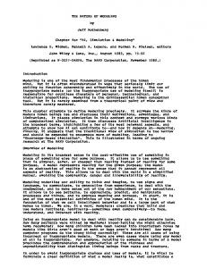
2. Overview of System Requirements For completeness, a brief introduction to statecharts is presented below. Statecharts are described as: statecharts = state-diagrams + depth + orthogonality + broadcast-communication, where state-diagrams illustrate the relation between statecharts and traditional finite state machine formalisms; depth describes the decomposition of states, exemplified by XOR constructs; orthogonality is used to describe concurrency and is exemplified by AND constructs; and broadcast-communication illustrates the random nature of events in the system. Statecharts can handle logical combinations of states where states are grouped by either XOR or AND-combinations. The XOR-combination of states allow state clustering. A cluster of states X1.a and X1.b, can be described by the state X1.d, as illus-
5. The term agent is used to denote a high level description of a part (component) in the system under development. An agent is defined as a collection of objects which closely coordinate and communicate to perform a common task or responsibility. Since it is an aggregation of objects, the agent itself can be referred to as an object.
6
trated in Figure 1a. Concurrency is represented by AND-composition. Concurrency allows two separate state machines to be specified by a single reference, as represented in Figure 1b. A default state can be specified for the XOR-combination so that a transition to a XOR-combination state causes a known behavior. Statecharts can also direct transitions from a state, A, to a substate, b, within a different state, B. Likewise the system can directly leave from a substate, a, of a state, A, to another state, B’, which is not at the same level as a. In a top-down system specification, lower level system details are abstracted. Hence, the exact details of the lower level system behavior can be left unspecified. This allows the designer to use similar high level specifications to implement completely different lower level system behaviors. Consequently, when specifying event transitions, an event is allowable in a state if it can cause a transition from the current state to another at the same level in the hierarchy. However, in order to promote reuse of specifications, a mechanism for encapsulating substate information should be defined. That is, within the specification of the behavioral model, the underlying substates within a state should be concealed from the external view of the state. Correspondingly, the implementation of the substate configuration can change without affecting the behavior of a higher level state. Statecharts provide an effective mechanism for this encapsulation. Since only the transitions into and out of the state need to be known to the outside world, the substate implementation is made private to the outside world. As noted in the communications model of Wittig (1992), it is useful to support both point-to-point and multi-cast message passing. This is because an object may have to announce some information to all interested objects. For example, many objects may be interested in sensory information (e.g., a shutdown event). In such instances, broadcast messages are appropriate. Broadcast messages are also useful for synchronizing objects (see Harel, 1987c). However, the traditional object-oriented message passing mechanism is point-to-point. That is, messages are directed to specific objects. Point-to-point messaging is useful when requesting(providing) a specific service from(to) an object. Due to the distributed nature of the system, ordering of events becomes crucial in certain situations. Therefore, the system should ensure basic characteristics of message communication. For example, the order in which a target receives messages must be the same order in which the source generates those messages. The implicit object communication model (IOC) of SMOOCHES models both broadcasting (either selective or full broadcast) and pointto-point message passing.
7
X1
X1 X1.d X1.a
X1.a
e3 e2
e1
X1.c
e3
e1 e2 X1.c
e2
X1.b
a
X1.b
XOR−combination X2 X2.a
X2.c e1
e1
X2.d
e3 e2
X2.b
X2.e
b AND−composition
Figure 1. Statecharts
To ease the transition from analysis and design to implementation, the application programming interface (API) should be simple and logically extendible throughout the system lifecycle. There must be a correspondence from the problem domain (what the objects do, or, system definition) to the solution domain (how the objects perform, or, system design). In the case of establishing state hierarchies in SMOOCHES, it is easy to add a state to an active object; to attach the action with its state, and to establish substates to those states. Moreover, in order to ease system development, especially when dealing with objects in distributed systems, a graphical simulation provides a convenient view of the system as it transitions through various states.
3. System Characteristics In this section the basic extensions to statecharts, the formulation of the exit-safe state notation, the implicit object communication model for reactive systems modeling, and a SMOOCHES specification language are introduced.
3.1. Exit-safe states Exit-safe states represent states wherein a substate lifecycle is in a stable state to process the transition out of a parent state. To illustrate, let s be a state where an outgoing transition t occurs on an event e. Let {a, b, c} be the set of
8
substates under s. When specifying the substate lifecycle for s, the developer may not desire an outgoing transition on s to occur until substate c is reached. Therefore, c, will be designated as an exit-safe state. In another implementation, a substate lifecycle may be defined by the substates in {a,b,c,d}, and c and d can be designated as “exit-safe”. Thus, t can occur in either state c or d of the substate lifecycle. Exit-safe states can be used in different ways to define certain desirable system characteristics. Figure 2. represents the graphical notation of exit-safe and non-exit-safe states. Figure 3 presents some examples of exit-safe states, where the shaded (parent or higher level states) states are those that conceal their underlying substate diagrams while the unshaded states (substates) are those whose substate lifecycles are not concealed.
Exit-safe state
Non exit-safe state
Figure 2. Exit-safe and Non exit-safe states.
The following three classes of substate configurations are distinguished: 1. XOR class: In this class, all of the substates of a parent state are exit-safe states. This configuration yields the same effect as the XOR-states in Harel (1987c). When a transition occurs for a state with an XOR class substate configuration, it immediately transitions to the next state (Figure 3a), regardless of the current substate of s. However, in real world applications it may not be practically feasible to abort some operations in such a manner. The exit-safe states, therefore, implicitly introduce this notion of non-preemptive (de)allocation of system resources and operations. 2. Single-exit class: In this class, a stream of substates terminates in an exit-safe state, such that it guarantees all of the substates are entered before exiting the parent state (Figure 3b). 3. Multi-exit class: In this class, a cycle exists among one or more substates which comprise the parent state and designate one or more of these substates as an exit-safe state(s). Thus, substate lifecycles are established and it is ensured that the parent state is in a stable substate before transitioning between parent states. For example, if a machine is to inspect a part at a certain point in its state lifecycle it would enter an Inspection state. The machine might then have a manipulator rotate the part while a camera inspects the part. It might take several passes to ensure that the part meets its specifications, but it could exit sooner if a defect is noticed. In such a case, the substate transition is a cycle between two states: (i) the state in which the manipulator is rotating the part, and (ii) the state in which the part is stopped in the appropriate position to continue. The manipulator would cycle between these two states until either a defect is found or the part
9
is determined to be defect-free (Figure 3c).
State
State
Event
a
Event
Superstate
Substate
b
Exit−safe Substates
Transition
c
Figure 3. Examples of exit-safe state usage
Similar to the definition in Harel, Pnueli, Schmidt, and Sherman (1987b), states are defined along with a hierarchy function,
ρ . A terminal type function ω is added to express the notion of exit-safe states. The hierarchy function
represents the substates of a state s. If S represents the set of all states in the system, then
ρ is defined by
S
ρ : S → 2 , where ρ ( s ) defines the immediate substates for a given state s. Two different states cannot have the same set of substates. Therefore, if
ρ ( x ) = ρ ( y ), x = y. The root state of the description is the state which is not
a substate of any other state. The root state, r, is unique and defined by following discussion,
( r ∈ S ) : ∀ ( s ∈ S ) r ∉ ρ ( s ) ) . In the
i 0 ρ denotes the substates i levels below s, ρ ( s ) denotes s itself, and ρ ( s ) denotes the
immediate substates of s, etc. Two extensions of
1
ρ are defined:
*
• ρ ( s ): This denotes s, all of the substates of s, the substates of those substates, and so on recursively. Thus, *
ρ ( s) =
i ρ . ∪ i≥0
10
+
• ρ ( s ): This represents all of the substates of s, the substates of those substates, and so on recursively, not including s. Thus,
+
ρ ( s) =
i ρ . ∪ i≥1
ω , is defined as below. It is used to define Ω , which determines the validity of a tran-
The exit-safe type function,
sition leading out of a state. Thus,
ω : S → { EXIT – S AFE, NONEXIT – SAFE}, Ω : S → { True, False }, and +
Ω(x) : in ( x ) ∧ ∀s ∈ ρ ( x ) : ( in(s) → ω(s) ), where in(x) denotes that the system is in state x.
Ω(x) returns true if the object is in a state, x, and all of the sub-
states which x is in are exit-safe. If a valid event occurs in state, x, the corresponding transition out of x can be processed if
Ω(s) evaluates to True.
The pended events function,
π(s), returns the events pended to a state. That is π : S → 2
the set of all legal events in a given state, s.
E
legal
, where
E legal is
π(s) returns a set of events which are to be processed when it is possible
to exit a state s. The set of transitions, T, defines a set of tuples. If (i) E is the set of all events in the system, (ii) G is the set of all guards in the system, and, (iii)
∆ is a tuple defined by ∆ ⊂ E × G , then the set of transitions, T, is defined by:
T⊂S×∆×S A transition t = (a, l, b), where a is a source state, l is a label, and b is a target state. The label, l, is defined by the set {e, g}, where e is an event and g is a guard. Transition, t, will occur iff: (1) the system is in a, and (ii) event e occurs, and (iii) guard g is True. Before proceeding further, let us define the following functions, used later in the paper:
• X : T → S , where X(t) returns the source state t, • L : T → ∆ , where L(t) returns the label associated with t, • L G ( g ) : L → { True, False }, where L G ( g ) ( t ) returns the evaluation of the guard associated with t,
11
• L E : L → E , where L E ( t ) returns the event associated with t, and • Y : T → S, where Y(t) returns the target state t.
3.2. Implicit Object Communication Implicit object communication (IOC) is a mechanism that defines interfacing methods between objects through event generation. Communication between objects is by means of events, whereby an event generated by an object causes a reaction in another object. Events implicitly invoke the methods within other objects. The interface is defined through event types instead of explicit function invocation. IOC is inherently more extensible than explicit function calls since objects can be added to, or removed from, the system, without affecting the object which generates the event. IOC is more modular than explicit function invocation since the method invoked by an event can be modified without changing the object which generates the event. Symbol
Meaning
e
Selective Broadcast of event, e
e
Point−to−point communication of event, e
Object A
i
i
j
j
Object B
k
Object C k
l i
Figure 4. Implicit Object Communication model
To specify the communication model of the system, the developer defines (i) the events that each object is interested in, that is, the events to which the object responds, and (ii) the events which each object generates. The events which cause transitions in the state model of an object correspond to the events in which that object is interested. From this definition, communication channels are implicitly derived. This communication mechanism allows for a
12
type of selective broadcast where information is transferred only to every object which desires it. A selective broadcast occurs when an object generates an event and other objects receive notification of that event. It is a broadcast since multiple objects receive the event information. It is selective since not all objects in the system receive this information (selective broadcast has also been referred to as multi-cast). If all objects in the system register interest in a certain event, the distribution of that event will reach all of the objects. Thereby, a full broadcast is achieved. Garlan and Scott (1993) mention several categories which define implicit communication. These categories include: (i) event definition, (ii) event structure, (iii) event bindings, and (iv) delivery policy. Different options for each category is discussed in Garlan et al. (1993). Section 6 discusses the implementation of (i) - (iii). The delivery policy, (iv), is a state-based policy. Depending on the state of the receiving object, the activity in response to the event will differ.
: : : : : : : : : : : :
: : : : : : : : : : : : : : : :
periodic interrupts eid
TIME PERIOD watch-dog
| | id | [, ] .id [, ] [, ] [, ] input | output | timed | error | periodic ; | || | | | periodic | | | [guard-exec ():] [TIME] exec () [guard-exec ():] [PERIOD] send () [guard-exec ():] [PERIOD] recv () [guard-exec ():] loop [TIME] do od do [interrupts] od do [PERIOD] od timeout [TIME] → | case error → [, ] eid [, ] eid [ ] operator id num num if timed : query (LIST); do od
Figure 5. The system specification language
Many systems require point-to-point communication. Point-to-point communication is specified by providing the destination object address when distributing the event. Figure 4 illustrates the graphical representation of the object
13
communication model. Arrows represent information flow. Each arrow is labelled with the event type it represents. An arrow with an arc leaving an object represents broadcast generation of an event. An arrow with an arc entering an object represents interest in an event. Objects connected by an arrow represent point-to-point communication in the direction of the arrow. In Figure 4, Object A generates events i and j and sends event l to Object C. Object B is interested in events i, j, and k. Object C receives l directly from Object A, is interested in i, and generates k.
3.3. System Specification Language The basic high level system structure and behavior is captured by the specification language in Figure 5. The syntax of the specification is similar to extended BNF (Backus - Naur Form) notation, where, (i) ‘|’ represents alternative syntax, (ii) ‘< >’ represents nonterminal symbols in the language, and (iii) ‘[ ]’ represent optional syntax. In addition, ‘||’ represents parallel activity, ‘;’ represents sequential activity, and ‘guard_exec: expr’ represents the execution of a guard before execution of expression, expr. If the guard evaluates to true, expr is executed. For more information on the specification and its application, the reader is referred to Ramaswamy (1994). This general high-level specification language is mapped to a specification language for SMOOCHES Certain modifications are made to the general specification model to obtain the specific specification language of SMOOCHES. These include: 1. ‘{}’ is used to represent inheritance. For example, STATE2: {STATE1} means that the definition of STATE2 is derived from STATE1. Figure 6 shows that inheritance can be used in defining agents, events, and states. Agent inheritance implies that the derived agent inherits both the information model and the state model of the base agent. 2. allows modification to the base class. A defines addition to the base definition or if an item within the base definition is to be redefined (polymorphism). The ‘=’ acts as a replacement operator to signify polymorphism within a derived class. 3. and are always bound to a message routing agent. The message routing agent then handles IOC. 4. has guarded options to represent guarded transitions.
14
5. send and recv contain an eid and an optional list. This representation is consistent with the IOC model discussed earlier. A selective broadcast send specifies only the eid. A point-to-point send specifies an eid as well as the destination id’s. The recv command is similar. .
: : : : : : : : : : :
periodic interrupts eid TIME PERIOD
: : : : : : : : : : : : : : : : : : : :
watch-dog
| | id | [, ] .id [{AGENT}] [, ] {EVENT} | [guard-exec():] timed | [guard-exec():] error | [guard-exec():] periodic [{STATE}] ; | || | | { []} | ; | || [, = | ; | || ||| [guard-exec():][TIME] exec() [guard-exec():][PERIOD] send(eid[, ]) [guard-exec():][PERIOD] recv(eid[, ]) [guard-exec():]loop [TIME] do od do [interrupts] od do [PERIOD] od timeout[TIME]; | case error; [, ] eid[, ] eid[] operator id num num if timed : query (LIST); do od
Figure 6. SMOOCHES specification language
This specification language maps to the visual representations as follows. Agents defined by , represent course grain groupings of objects. These groupings define communications sources and receiving points. can be thought of as processes on individual machine. They are represented by boxes in the object communication model to denote how the communication channels are defined in the system. Events, defined by , cause transitions in the state models. Events are represented graphically as labels on the transitions between states. States, defined by , are either comprised of a sequential sequence of states (XOR-combi-
15
nations), parallel states (AND-composition), or as operations.
4. Modeling Behavioral Characteristics Modeling significant activations of and constraints on behaviors must be formally specified. The following subsections discuss the formal behavioral specifications of SMOOCHES: 1) Special Events, B) Pending Events, C) Timing characteristics, and D) Guards on transitions.
4.1. Special Events Events also maintain a class hierarchy. Therefore, it is possible to derive classes of events from base class events (i.e., the derived events will enable the same transitions as the base class enabled). Two types of events are derived from the general event class, the special events,
E χ , and the basic events, E B . All other types of events in the sys-
tem are derived from these classes. There are certain events (such as an error event) for which it is desirable to exit a state even if it is not in a terminal state. In such cases, it is necessary to define special event types that will exit a state regardless of its current substate. These types of events will allow the system to immediately handle exceptions, errors, or to process special interrupts which require immediate attention. This special type of event belongs to All other events are basic events, cial events,
Eχ .
E B . The set of all events in the system, E, is defined as the union of all of the spe-
E χ , and the basic events, E B . Thus, E = E χ ∪ E B and E χ ∩ E B = ∅ .
4.2. Pending Events For an application, it is necessary to define the effect of pending events on system behavior. Receiving two or more events in a state in which the current substate is not exit-safe is handled in different ways depending on the type of events. The capabilities provided by SMOOCHES for event handling is discussed in this section. 4.2.1 Special / Error events. If the incoming event, e i , is an error event, then it is processed immediately. That is:
t in ( Y ( t ) ) , where L ( t ) = e . ei ∈ Eχ ⇒ i n ( s) → E i 4.2.2 Basic events. Let
E s denote the current set of events associated with the outgoing transitions of a given state s.
Then an incoming event, e i , which is a basic type (i.e., e i ∈
16
E B ) could be processed in four different ways depend-
ing upon the particular application. These four different event handling methods are described below in subsections 4.2.2.1 through 4.2.2.4. 4.2.2.1 Pend only one event. This method is useful in detecting errors with timing or causal relationships of events and is easy to implement. This is useful in low level specifications, where the system must be specified to perform deterministically. Multiple pended events are assumed to signify a problem within the system. Given that only one transition can occur out of a state, the extra event shows that the system did not exit the state at the appropriate time. This could signify possible deadlock conditions since the object has been active in a certain state for too long. That is, the object should have transitioned out of the current state before the extra event arrived.
( e i ∈ E B ⇒ ( E s = E s ∪ e i ) ) iff ( ∃ ( t ∈ T ) : ( X ( t ) = s ) ∧ ( L E ( t ) = e i ) ) ∧ ( Es = ∅) 4.2.2.2 Pend all events; process only one event. The advantages of this method are: (i) it saves the event until it can be processed, and (ii) it is useful in detecting errors with guards. Multiple pended events are therefore legal, however, it is assumed that only one transition can occur. Since a guard can be attached to a transition, when it is due to process the list of pended events, only one transition will be taken since only one guard should evaluate to true. Thus, only one event-guard pair will be valid. If this is not the case, an error is considered to have occurred in the system.
( e i ∈ E B ⇒ ( E s = E s ∪ e i ) ) iff ∃ ( t ∈ T ) : ( X ( t ) = s ) ∧ ( L E ( t ) = e i ) 4.2.2.3 Overwrite old events with new events. The advantages of this method are: (i) the event information is always current, and (ii) since old data is removed, this method saves on storage space. If the same event occurs multiple times, the new event overwrites the old pended event. This method is useful when receiving sensory data periodically. The new data will replace the old sensory data until it can be successfully processed. (i)
(ii)
( e i ∈ E B ⇒ ( E s = E s ∪ e i ) ) iff ( ∃ ( t ∈ T ) : ( X ( t ) = s ) ∧ ( L E ( t ) = e i ) ) ∧ e i ∉ E s ( ( e i ∈ E B ) ∧ ∃ ( e j ∈ E s ) : ( e i = e j ) ) ⇒ iff ( ∃ ( t ∈ T ) : ( X ( t ) = s ) ∧ ( L E ( t ) = e i ) ) ( Es = ( Es – ej) ∪ ei)
4.2.2.4 Pend all events, process one event, and send the remaining events to the next state. The advantage of this
17
method is that the events are buffered so that no events are lost. Events are pended until they can be used for a transition. Cases (ii) and (iii) (below) indicate the situations wherein the pended events can be processed (i.e.
Ω ( s ) = True ). The events not used for the transition are passed along to the next state. The new state will then process those events. In this case, events are treated as persistent and the object needs to act upon them. (i)
( e i ∈ E B ⇒ ( E s = E s ∪ e i ) ) iff ∃ ( t ∈ T ) : ( X ( t ) = s ) ∧ ( L E ( t ) = e i ) Ω ( s ) ∧ ( ∃ ( t ∈ T ) : ( ∃ ( e ∈ Es ) : ( LE ( t ) = e ) ∧ LG ( g) ( t ) ) )
(ii)
If
(iii)
Then,
(iv)
¬in ( s ) ⇒ ( E s = ∅ )
( E Y ( t ) = E s – e ) , ( E s = ∅ ) , ( in ( Y ( t ) ) )
4.3. Timing characteristics For time-dependent behavior specifications, the specification of timing characteristics of the states is important. In SMOOCHES, every state is associated with a minimum time, by the pair
α , and a maximum time, β , for execution and denoted
( α, β ). The minimum time for a state, s, designates the amount of time which the system must stay in s,
before executing a transition out of s. The maximum time for a state, s, designates the maximum amount of time which the system can remain in state s. Associating time with higher level abstractions and maintaining its consistency with lower level specifications leads to a complex timing structure. Therefore, hierarchical state specification leads to constraints on the state timings. The
( α, β ) pair of the parent state constrains the timing specification of its children. Before proceeding fur-
ther, let us define the following terms, used later in the discussions.
• s(i): This denotes the ith child of state s; • s(1): This denotes the first substate of s entered when s becomes a current state; • τ : This is a time variable. α s denotes the lower time bound for a state, s;
18
• β s : This denotes the upper time bound for a state, s; AND AND • α s ( i ) , β s ( i ) : This denotes the upper and lower time bounds for the ith child of s in an AND composition; XOR XOR • α s ( i ) , β s ( i ) : This denotes the upper and lower time bounds for the ith child of s in an XOR composition; S
• C β : This is a function such that C β : 2 → τ . Now, C β ( Z ) maps a set of states, Z, to time, τ β , such that τ β represents the sum of the
∑
β ’s of the states in Z. That is, C β ( Z ) =
i : s ( i) ∈ Z
βs ( i) ;
S
• C α : This is a function such that C α : 2 → τ . Now, C α ( Z ) maps a set of states, Z, to time, τ α , such that τ α represents the sum of the α ’s of the states in Z. That is, C α ( Z ) =
s
s
• path : This is a function such that path : ρ ( s ) × ρ ( s ) → 2
2
∑
i : s ( i) ∈ Z
ρ ( s)
. Then,
αs ( i) ;
s
path ( x, y ) returns the set of
substate sets. Each substate set represents a possible path of states from substate x to substate y linked by a set of transitions in the system; s
• path ( x, y ) : This defines the number of substate sets (i.e., the number of paths from x to y); s
s
• path j ( x, y ) : This defines the jth path (i.e., substate set) of path ( x, y ) . A parent state will constrain the timing specification of its children in the following ways, depending on whether it is an AND or a XOR-composition of the respective states. AND Compositions: The minimum time of the state, s, is equal to the maximum of the minimum times of its constituent AND-states. The maximum time spent in s is equal to the minimum of the maximum times spent in its substates. That is,
AND α s = max α s ( i ) i
and
AND β s = min β s ( i ) . i
For example, Figure 7 illustrates a state A which has constituent AND states, 1, 2, and 3. The lower bound for state
19
A,
α A , is equal to the maximum of the minimum times of its substates. In this example, α A = 2. The upper time
bound for state A,
β A , is equal to the minimum of the maximum times of its substates. In this example, β A = 3. ( α A, β A ) A
(2,3)
(1,4)
1
(2,5)
2
3
Figure 7. AND-Composition timing example
XOR Compositions: To compute the timing characteristics of states with XOR substates, two important cases are distinguished: (i) acyclic and (ii) cyclic. These two cases are discussed below in detail. A
( αA ( 2) , βA ( 2) )
( α A, β A )
2 1 3
a
( αA ( 1) , βA ( 1) )
4
P
( α A, β A )
2
1
N
( αA ( 4) , βA ( 4) )
( αA ( P) , βA ( P) )
A
b
( αA ( 3) , βA ( 3) )
3
4
( αA ( 4) , βA ( 4) )
Figure 8. Cyclic Substates - Example 1
20
Case 1: Acyclic:
α s is the minimum of the sum of α s ( i ) ’s of all of the paths from the initial substate to an exit-safe substate and β s is the maximum of the sum of β s ( i ) ’s for all of the paths from the initial substate to an exit-safe substate. Therefore, s
∀j, s ( i ) : 0 < j ≤ path ( s ( 1 ) , s ( i ) ) , ( ω ( s ( i ) ) = Exit – Safe ) : s α s = min C α pathj ( s ( 1 ) , s ( i ) ) , and, s
∀j, s ( i ) : 0 < j ≤ path ( s ( l ) , s ( i ) ) , ( ω ( s ( i ) ) = Exit – Safe ) : s β s = max C β pathj ( s ( I ) , s ( i ) ) . Case 2: Cyclic: When cycles are allowed in substate descriptions, timing bounds are computed differently. The minimum time is still the shortest path to a terminal state. However, the maximum time can only be specified by a top down approach, describing a limit on the number of times a cycle can be traversed. For example, Figure 8a illustrates a simple substate cycle for state A. Each state has a time bound,
( α, β ). To analyze the cycles, sequential substates are grouped
into a pseudo-state, P, which has sequences and time bounds calculated from the substates within the group (Figure 8b). Therefore,
C β ( P ) = β A ( 1 ) + β A ( 2 ) + β A ( 3 ) and C β ( { A ( 4 ) } ) = β A ( 4 ) .
Let N be the number of times the current substate of A alternates between P and A(4). Then,
βA N ≤ ------------------------------------------------------------ . Cβ ( P) + Cβ ( { A ( 4) } ) Figure 9a illustrates a case with multiple cycles in the substate description of state A. To analyze the cycles, sequential substates are grouped into a pseudo-state, P, which has sequences and time bounds calculated from the substates within the group (Figure 9b). Therefore,
C β ( P1 ) = β A ( 1 ) + β A ( 2 ) , C β ( P2 ) = β A ( 3 ) + β A ( 4 ) , and, C β ( { A ( 5 ) } ) = β A ( 5 ) .
21
A
( α A, β A )
( αA ( 5) , βA ( 5) )
a
5
( αA ( 2) , βA ( 2) )
2 1
3
( αA ( 1) , βA ( 1) )
( αA ( 4) , βA ( 4) )
4
A
( αA ( 3) , βA ( 3) )
( α A ( P1 ) , β A ( P1 ) ) P1
( αA ( 5) , βA ( 5) )
( α A, β A )
N2
1
b 2
N1 5
P2 4
( α A ( P2 ) , β A ( P2 ) )
3
Figure 9. Cyclic Substate- Example 2
Let N1 be the maximum number of times the current substate of A can alternate between P1 and P2, and N2 be the maximum number of times the current substate of A can alternate between P1 and A(5). Then,
βA βA N1 ≤ ------------------------------------------------ , and, N2 ≤ --------------------------------------------------------------- . C β ( P1 ) + C β ( P2 ) C β ( P1 ) + C β ( { A ( 5 ) } )
4.4. Guards on transitions Guards are boolean expressions denoting conditions on a transition from one state to another. Guards are used to specify extra information for a state transition. The transition will occur only if the guard evaluates to true when the corresponding event occurs. A guard is optionally specified by the developer with the transition. Guard expressions
22
are made of either event or other state specifications. In the present implementation, guard expressions are simple logical expressions between events. These guard expressions, in the future, will have the ability to evaluate temporal specifications between events and states, thereby providing the ability to specify certain real-time constraints.
5. Deployment of Inheritance SMOOCHES deploys inheritance with respect to classes, state lifecycles, and event handling. These are discussed below in this section.
5.1. Class inheritance Classes contain object information and methods. Inheritance of class structures provides an organization for objects which promotes reuse of both information and methods. A derived class “inherits” the information and methods of a base class. A class hierarchy shows the information and method relationships between classes. Class inheritance of the active objects developed in the system are implemented using C++. The user develops classes to contain the information model as well as the methods for each active object in the system. Since some of the methods within the active object represent actions within certain states, action inheritance is the same as method inheritance. Therefore, when deriving a new class from an active object class, the states and the actions performed in the states are inherited. This feature allows the user to apply polymorphism to actions within a state. Thus, it permits a derived class to write a function with the same name and have it used instead of the base-class function wherever the base-class function would have been used. Thus, the derived class can have the same states and transitions as the base class but different actions performed in certain states. For example, if a derived robot class performed forward kinematics calculations differently (than its base class), then the developer can declare the base class forward kinematic calculation action as virtual and rewrite it within the derived class. Therefore, when the event to transition a robot object into the forward kinematic calculation state occurs, the derived robot class action is executed.
5.2. State lifecycle inheritance The specification of the states and transitions amongst those states are declared by the constructors for the objects.
23
Inheritance of a base class will involve calling the constructor and thus instantiating the states of that class. If it is desired to change the function of a state, polymorphism can be used to overwrite the action to be performed in the state. After the base class constructor is called and the base states instantiated, the derived class is then free to define new transitions to and from the states of the base class. Some restrictions have to be placed on inheritance of state diagrams in order to ensure logical consistency. Coleman et al. (1992) suggest the following restrictions for subtyping in their extension of Statecharts, called “Objectcharts”: 1. Add an extra state or transition corresponding to a new service, 2. Strengthen a transition specification by weakening its firing condition or strengthening its post condition, or, 3. Strengthen an invariant relationship. These restrictions basically ensure that the derived state will fire at least as often as the base state and it will result in the original post condition. Substates can also be added to the derived class as well as the base class states. For an event, e, foreach if
t ∈ T : in ( X ( t ) ) ∧ ( ( L
E
( t ) = e ) ∧ LG ( g) ( t ) )
Ω ( X ( t) ) ∨ ( ( e ∈ Eχ) ) then
else
in ( Y ( t ) )
pend ( e, X ( t ) )
endif endforeach
Figure 10. Algorithm for safe handling of exit-safe states
5.3. Exit-safe state handling within state hierarchies As mentioned in Section 3, the exit-safe state concept is implemented in this support environment. With the concept of the exit-safe state comes the need to pend events. When an event occurs which is legal in the current state but the state is in a substate which is not exit-safe, the system pends the event and will process it as soon as it enters a substate which is exit-safe. By allowing the pending of events, the system maintains consistency with the specification. The specification implies that the event is part of a legal transition for the current state and thus, should be processed for that state. However, the system is not at a point where it has completed its operations in that state (that is,
24
since the substate of the system is not exit-safe, the substate cycle is not finished or it is not at a stable point). Therefore, the system waits until the state is completed (designated by entering an exit-safe substate) and then continues by processing the pending events.Therefore, a transition is enabled when: (i) The event(s) associated with the transition occurs, (ii) The guard evaluates to True, and, (iii) All current substates are exit-safe (i.e.,
Ω ( s ) = True ). The
algorithm in Figure 10 is implemented to safely handle transitions with exit-safe states. The algorithm is illustrated by the flowchart in Figure 11. The order of execution of the potential transitions is non-deterministic6. Therefore, a transition will occur iff:
∃ ( t ∈ T ) : in ( X ( t ) ) ∧ ( e = L E ( t ) ) . On reaching an exit-safe state and perform-
ing the action associated with that state, the pending events need to be processed. Choices regarding the modeling of pending events is domain and application dependent.
For each transition, t If the following criteria are met:
. the system is in the state, s, from which t is outgoing, .the incoming event, e, enables t, and, .the guard associated with t evaluates to true.
ELSE THEN
ELSE
If all of the current substates of s are exit-safe or e is a special event type which exits a state even if the state’s current substate is nonexit-safe.)
THEN
Pend the event to state s.
Take transition t. The system is then the new state to which t leads.
Figure 11. Flowchart of the algorithm
6. Implementation The SMOOCHES environment has been implemented in C++ utilizing the InterAgent toolkit for implementing the distributed communication mechanism. The SMOOCHES implementation is discussed in detail in this section. 6. It is not guaranteed that a specific transition will take place, unless the specified system itself has a mechanism for guaranteeing the order of transition execution.
25
6.1. Framework The SMOOCHES environment is organized into several classes: Agent, ActiveObject, TransitionElement, and StateClass. The environment is implemented in C++. The C++ language provides the necessary inheritance features of the information model as well as virtual functions for changing base class methods within derived classes. A simplified model of the construction of these classes is shown in Figure 12 using Rumbaugh’s Object Model Notation (see Rumbaugh et al., 1991). Figure 12 illustrates that the Agent class, the most basic class defined, is common to all of the classes in the environment. The Agent class contains the information and methods to handle the message communications between distributed processes. The ActiveObject forms the next most basic class. It is comprised of several states and several transitions which combine to make up the state lifecycle of the object. Th ActiveObject class contains the information and methods to handle the processing of events received by the agent.
Key Agent
Inheritance Aggregation
ActiveObject List of States
Contains zero or more
List of Transitions
StateClass
TransitionElem Event List of Pending Events
stateType Terminal or Nonterminal Action
Action to be Executed when Entering State
StateClass Current State Event StateClass Event Triggering NextState Transition
Figure 12. Basic object notation for the environment
Processing the events involves the following: (i) determining whether the event is legal for the current state of the ActiveObject, (ii) either pending the event or evaluating the transition to the next state, and (iii) evaluating corresponding guards placed on a transition. State information is represented in the StateClass. The StateClass defines the state of the ActiveObject as well as the methods of the ActiveObject to be invoked when entering that state.The transitions are represented by the TransitionElem class. The TransitionElem class defines how the ActiveObject responds to
26
events. When constructed, the active object specifies the event, the state in which the event is legal, the destination state, and optionally, a guard. All user-defined ActiveObjects should be derived within the ActiveObject class. By appropriate abstractions, the developer promotes reuse throughout the system development process. A top-down specification defines the basic state flow for an active object in a class. Derived classes from that basic state define details of the substates for the state specified. If the substate definition changes but the basic high-level state definitions remain intact, the base class can be reused.
6.2. Communications The InterAgent toolkit for distributed system development has been chosen to provide the backbone for communication management (Modulus, 1993). It supports many platforms including the Sun, Silicon Graphics, and PC environments, thereby providing an open system development environment. InterAgent implements IOC by supporting point-to-point and selective broadcast message passing. InterAgent also provides timer functions, which are used to activate state timing error conditions. If the timer expires before the object exits the state, an error is generated. The following table illustrates the implementation of IOC through InterAgent.
IOC Requirements
InterAgent Implementation
Event Definition
Static Event Declaration
Event Structure
Parameters by Announcement
Event Bindings
Dynamic Event Bindings
Summary
Events are declared and defined at compile time Parameters within the event can specify a list of parameters in the form of a structure. Agents register interest in objects dynamically at runtime
TABLE 1. IOC by InterAgent
7. Example: An Assembly Robot The following example illustrates the modeling and simulation capabilities of SMOOCHES. A simple assembly robot is modeled. The example develops the class hierarchies of the information model and the state life-cycles and shows some output of the monitor program that simulates the state lifecycles.
27
7.1. High-Level Specification Figure 13 is a trace of the high level SMOOCHES specification of an assembly robot within a workcell. The assembly robot description is comprised of a basic definition of an assembly robot and two derived robots based on the basic definition. The specification of this system demonstrates the use of a router. The router will direct messages to all agents interested in those messages generated by a particular agent. It provides the means for IOC. The derived assembly robots, AssemblyRobot1 and AssemblyRobot2, have different implementations of the PartAtStation state as denoted by the replacement operator ‘=’ following the inheritance. A more detailed description of the system and the corresponding visual description follows.
: : :
....
: : : :
ba_id ; ; ; ; ; {BasicAssemblyRobot} = ; ; {BasicAssemblyRobot} = ;
Figure 13. Trace of assembly system specification
7.2. Assembly Robot Base Class The assembly robot example consists of an assembly robot which goes through six basic states: (i) idle, (ii) part at station, (iii) assembling part, (iv) advancing part, (v) discarding part, and, (vi) homing manipulator. These states and the corresponding event transitions are shown in Figure 14. Idle
Assemble
Part at Station
Attach
Discard
Attaching Subparts
Discarding Part
Advance Advancing Assembly
Home
Done
Home Homing Manipulator
Figure 14. Basic state model of assembly operation
28
7.3. Implementation Two implementation scenarios are distinguished and described below: (i) handling inspection within the manipulator agent and (ii) handling inspection by a separate agent. Each scenario involves the six basic steps outlined above, so that a base class is developed to handle the six basic states and their transitions. Two derived classes inherit the information and state characteristics of the base class but add different sub-state actions to handle the different scenarios. The case in which inspection is handled directly by the assembly robot agent involves adding sub-states to the Part At Station state. During this state, the robot will inspect and then grab the part and attach it to the subassembly. The sub-states are represented in Figure 15.
Part At Station Positioning Manipulator
Grab Grabbing Subpart
Inspect Inspecting Subpart
Figure 15. Substates of PartAtStation state for scenario 1
Part At Station Positioning Manipulator
Grab Grabbing Subpart
Figure 16. Substates of PartAtStation state for scenario 2
Figure 14 illustrates that after performing the inspection, either event Attach or event Discard will be generated and the robot will move into the appropriate state. The state Inspecting Subpart, in Figure 15, is an exit-safe state. After reaching this state, the assembly robot can then transit out of the parent state, Part At Station, and continue to the
29
appropriate state. The other scenario involves a separate agent performing the inspection. Again, the basic states of the assembly robot are the same, just the substates of Part At Station are different. The base states are thus inherited. The derived assembly robot class will then have substates of Part At Station as illustrated in Figure 16. The separate inspection agent will then send either the Attach or the Discard events while the assembly robot is in the Part At Station state. That event will pend until the assembly robot finishes the Grabbing Subpart state since that state is an exitsafe state.
7.4. System Simulation Once the system state transition model has been derived and represented, the monitor is used to simulate the model across non-homogeneous platforms. The simulation contains iconic representations of the agents in the system under development. The simulation traces the communication and state transitions of the agents during the course of a system execution. Figures 17 through 21 provide snapshots of the simulation of the assembly robot. The simulator is interactive and provides the following monitoring capabilities (i) Monitoring overall system operations, (ii) monitoring system communications (iii) selectively observing state hierarchies and (iv) observing legal state transitions. These are illustrated below. 1.
Monitor Overall System Operations: Figure 17 displays the different agents within the system. When an agent process is started, it announces this fact to the monitor which then places an icon in the window. In this example, there are two assembly robots, AssemblyRobot1 and AssemblyRobot2, and a control window, CNTRLWIN. The two assembly robots are implementations of those discussed in the example, and the control window is used to manually send events to the processes.
2.
Monitor Communications: This facility is used to monitor the communications of any agent in the system. Figure 18 illustrates a popup window that displays the messages sent from and received by an agent. In this case, agent AssemblyRobot1 has received a series of events from CNTRLWIN.
30
Figure 17. Agent icon popup window
3.
Figure 18. Event history popup window
Observe State Hierarchies: States belonging to different hierarchical levels can be easily observed. Moreover, those states that have a lower level state description can be selectively explored to monitor the substates of the current state. Figure 19 shows the top level state transition diagram popup window. In this case, it shows the top level state transition diagram of AssemblyRobot1.
Figure 19. Top level state transition diagram popup for assembly robot 1 (Darkened state represents current state)
Current states of the agent are represented by the “filled” state. This facility is used to monitor the state transitions of any agent in the system. Figure 20 shows part of the substate popup window for AssemblyRobot1. Here, since the first substate is the current substate of the system (notice that the current state is PartAtStation, and the substate is
31
PosManip). The InspectSubpart is an exit-safe state.
Figure 20. Substate transition diagram popup for state PartAtStation (Darkened state is the current state)
4.
Observe Legal State Transitions: At any given stage, it is possible to observe the legal transitions that are valid for a particular state. Figure 21 illustrates the legal transitions from and to this state.
Figure 21. PartAtStation transition list popup window
8. Conclusions A visual hierarchical behavioral specification environment to support object-oriented analysis and design in distributed systems has been presented. A specification language which extends the general system specification language presented in Ramaswamy and Barber (1995) has been presented to allow high level descriptions of reactive, statebased systems. This specification is supported by the development tool environment. Deployment of the specification provides the following: 1. A visual and hierarchical transition model for objects in a distributed environment: Since SMOOCHES extends from Statecharts, a complete visual notation for the behavioral model is given. SMOOCHES introduces the notation of exit-safe states, thereby providing greater expressive power to statecharts in modeling distributed, reactive systems. 2. Object-oriented features like inheritance, encapsulation, and polymorphism within the state transition model:
32
This behavioral specification is an improvement over other techniques because it combines an object-oriented view of the behavioral aspects of a system with a concise visual formalism to promote reuse of system specifications.
• Inheritance provides a mechanism for reusing high level specifications by “inheriting” the behavioral models from base classes to derived classes.
• Encapsulation provides a mechanism for concealing the substate definitions. Thus, a state, s, encapsulates its substate information. This promotes modularity of state definitions. 3. Polymorphism provides a mechanism for changing state functionality. That is, the activity done by a state can be modified in a derived class. 4. An extension to hierarchical state specification called exit-safe states: The concept of exit-safe states in an objectoriented environment allows respecification of substate definitions without modifying higher level state specifications. The substate definitions are completely encapsulated within their parent state. The notion of exit-safe states is unique to the SMOOCHES environment. Several mechanisms for pending events when a state is not in a terminal substate have been presented. 5. An extensible communication mechanism which can operate across heterogeneous platforms: The IOC model of SMOOCHES provides an extensible and modular medium for object-oriented, distributed system development. This model provides a selective broadcast mechanism which allows modular multicast binding of message channels. The modeling formalism within SMOOCHES allows for the transformation of generic high level system specifications to specific lower level specifications. Exit-safe states and the timing characteristics for state descriptions with exit-safe states has also been defined. These features in SMOOCHES provide the developer the capability for automated verification and reasoning about system properties. The SMOOCHES support tool is implemented in C++. It provides mechanisms for handling hierarchical state descriptions with exit-safe states. SMOOCHES is built to execute along with InterAgent, which is used to handle IOC. A graphical monitoring system has been developed to allowing the viewing of state transitions. The current implementation, as described in this paper, provides a formal environment for the development object-
33
oriented distributed systems. It supports hierarchical state specification and implementation, inheritance of state lifecycles within active objects, guarded transitions on events, and the useful notion of exit-safe states. The graphical monitoring system developed along with the environment provides visual feedback for system development. This monitoring system understands the hierarchies of the lifecycles specified by the environment and monitors the events and the state transitions which occur in the system by displaying arrows and highlighting icons. The user can also obtain a list of events and possible transitions by using mouse inputs. In the future, a graphical tool for system specification and a code generator to generate the appropriate code C++ code as required by the environment is proposed. Also, as stated earlier, the use of temporal logic to specify timing characteristics between the events that trigger various system operations will be incorporated.
34
9. References Agha, Gul A., ACTORS: A Model of Concurrent Computation in Distributed Systems, The MIT-Press, Cambridge, MA (1986). Alford, M. W. , J.P. Ansart, G. Hommel, L. Lamport, B. Liskov, G. P. Mullery, and F. B. Schneider, “Distributed Systems: Methods and Tools for Specification,” Lecture Notes in Computer Science 190, Springer-Verlag, NY, pp. 270 - 285 (1985). Alpern, B. and F. Schneider, “Defining Liveness,” Information Processing Letters, Vol. 21, No. 4, pp. 181 - 185 (October 1985). Barcio, B. T., S. Ramaswamy, R. Macfadzean, and K. S. Barber., “Object-Oriented Analysis, Modeling and Simulation of a Notional Radar Tracking System”, Simulation, Vol. 66, No. 1, pp. 5-21 (January 1996). Basye, Kenneth, Thomas Dean, Jak Kirman, and Moises Lejter, “A Decision-Theoretic Approach to Planning, Perception, and Control,” IEEE Expert, Vol. 7, No. 4, pp. 58 - 65 (1992). Bear, S., P. Allen, D. Coleman, and F. Hayes., “Graphical Specification of Object Oriented Systems,” ECOOP/OOPSLA 1990 Proceedings, Ottawa, Canada, pp. 28 - 37, (October 1990). Booch, Grady, Object Oriented Design with Applications, The Benjamin/Cummings Publishing Company, Inc., Redwood City, CA (1991). Brave, Y. and M. Heymann, “Control of Discrete Event Systems Modeled as Hierarchical State Machines,” IEEE Transactions on Automatic Control, Vol. 38, No. 12, pp. 1803 - 1819 (December 1993). Cherry, G. W., “Stimulus-Response Machines: A New Visual Formalism for Describing Classes and Objects,” ACM SIGSOFT Software Engineering Notes, Vol. 18, No. 2, pp. 86 - 95 (April 1993). Ciscon, Lawrence A., “A Communications and Interaction Model for Intelligent Cooperating Robots,” Doctoral Dissertation in Electrical Engineering, Rice University, Houston, Texas, USA, (May 1993). Coleman, D., F. Hayes, and S. Bear., “Introducing Objectcharts or How to Use Statecharts in Object-Oriented Design,” IEEE Transactions on Software Engineering, Vol. 18, No. 1, pp. 9 - 18 (January 1992). Davis, Alan, “A Comparison of Techniques for the Specification of External System Behavior,” Communications of the ACM, Vol. 31, No. 9, pp. 1098 - 1115 (September 1988). Gabrielian, Armen and Matthew K. Franklin, “Multilevel Specification of Real Time Systems,” Communications of the ACM, Vol. 34, No. 5, pp. 51 - 60 (May 1991). Ganti, M., P. Goyal, and S. Podar,“An Object-Oriented Software Application Architecture,” Proceedings of the 12th International Conference on Software Engineering, Long Beach, CA, pp. 212 - 220, (1990). Garlan, D. and C. Scott, “Adding Implicit Invocation to Traditional Programming Languages,” Proceedings of the 15th International Conference on Software Engineering, Long Beach, CA, pp. 447 - 455, (1993).
35
Goldstein, Neal and Jeff Alger, Developing Object-Oriented Software for the Macintosh: Analysis, Design, and Programming, Addison-Wesley Publishing Company, Inc., Reading MA (1992). Gossain, S. and B. Anderson, “An Iterative-Design Model for Reusable Object-Oriented Software,” ECOOP/OOPSLA 1990 Proceedings, Ottawa, Canada, pp. 13 - 27, (October 1990). Harel, D., H. Lachover, A. Naamad, A. Pnueli, M. Politi, R. Sherman, A. Shtull-Trauring, and M. Trakhtenbrot., “STATEMATE: A Working Environment for the Development of Complex Reactive Systems,” in Software State-of-the-Art: Selected Papers, Tom DeMarco and Timothy Lister, editors, Dorset House, NY, pp. 322-338 (1990). Harel, D., “On Visual Formalisms,” Communications of the ACM, Vol. 31, No. 5, pp. 514 - 531 (May 1988). Harel, D., Algorithmics: The Spirit of Computing, Addison-Wesley Publishing Company, Inc., Reading, MA (1987a). Harel, D., A. Pnueli, J. P. Schmidt, and R. Sherman, “On the Formal Semantics of Statecharts,” Proceedings of the 2nd IEEE Symposium on Logic of Computer Science, Ithaca, NY, pp. 54 - 64, (1987b). Harel, D., “Statecharts: A Visual Formalism for Complex Systems,” Science Computer Program., Vol. 8, No. 3, pp. 231 - 274 (June 1987c). Harel, D. and A. Pnueli, “On the Development of Reactive Systems,” Logics and Models of Concurrent Systems, NATO, ASI Series, Vol. 13, K.R. Apt, Ed. Springer-Verlag, NY, pp. 477 - 498 (1985). Hoare, C. A. R., Communicating Sequential Processes, Prentice Hall, Englewood Cliffs, NJ (1985). Ingrand, F.F., M.P. Georgeff, and A.S. Rao, “An Architecture for Real-Time Reasoning and System Control,” IEEE Expert, Vol.7, No. 6, pp. 34-44, (1992). Järvinen, H. M., R. Kurki-Suonio, M. Sakkinen, and K. Systa, “Object-Oriented Specification of Reactive Systems,” Proceedings of the 12th International Conference on Software Engineering, Long Beach, CA, pp. 63-71, (1990). Nielsen, K., Ada in Distributed Real-Time Systems, McGraw-Hill Book Company, NY (1990). Lafontaine, Christine, Yves Ledru, and Pierre-Yves Schobbens, “An Experiment in Formal Software Development: Using the B Theorem Prover on a VDM Case Study,” Communications of the ACM, Vol. 34, No. 5, pp. 63 - 71 (May 1991). Lamport, L., “A Simple Approach to Specifying Concurrent Systems,” Communications of the ACM, Vol. 32, No. 1, pp. 32 - 45 (January 1989). Linster, Marc, “Closing the Gap Between Modeling to Make Sense and Modeling to Implement Systems,” International Journal of Intelligent Systems, Vol. 8, pp. 209 - 230 (1993). Modulus Technologies, Interagent Toolkit User’s Manual, Modulus Technologies, Inc., Houston, Texas, USA, (1993). Nicollin, X., J. Sifakis, and S. Yovine, “Compiling Real-Time Specifications into Extended Automata,” IEEE Transactions on Software Engineering, Vol. 18, No. 9, pp. 794- 804 (September 1992).
36
Nierstrasz, O. and M. Papathomas,“Viewing Objects as Patterns of Communicating Agents,” ECOOP/OOPSLA 1990 Proceedings, Ottawa, Canada, pp. 38- 43, (October 1990). Oswald, H., R. Esser, and R. Mattmann “An Environment for Specifying and Executing Hierarchical Petri Nets,” Proceedings of the 12th International Conference on Software Engineering, Long Beach, CA, pp. 164-172, (1990). Pnueli, A., “Applications of Temporal Logic to the Specification and Verification of Reactive Systems: A Survey of Current Trends,” in Current Trends in Concurrency, J. W. de Bakker et al., Eds. Lecture Notes in Computer Science, Vol. 224, SpringerVerlag, NY, pp. 510 - 584 (1986). Ramaswamy, S., “Hierarchical Time-Extended Petri Nets (H-EPNs) for Integrated Control and Diagnostics of Multilevel Systems,” Doctoral Dissertation, The Center for Adv. Comp. Studies, The University of SW Louisiana, Lafayette, LA, (May 1994). Ramaswamy, S. and K. S. Barber, “A High Level Specification Mechanism for the Analysis and Design of Manufacturing Systems”, IEEE International Conference on Systems, Man, and Cybernetics, pp. 524-529, Vancouver, British Columbia, Canada (October 1995). Rumbaugh, J.,M. Blaha, W. Premerlani, F. Eddy, and W. Lorensen, “Object-Oriented Modeling and Design,” Prentice Hall, Englewood Cliffs, NJ (1991). Rumbaugh, J., “State Trees as Structured Finite State Machines for User Interfaces,” Communications of the ACM, Vol. 10, No. 15, pp. 15 - 29 (October 1988). SES, SES/Objectbench User’s Manual, SES, Austin, Texas, USA, (1993). Shaw, Alan, “Communicating Real-Time State Machines,” IEEE Transactions on Software Engineering, Vol. 18, No. 9, pp. 805 816 (September 1992). Shlaer, Sally and Stephen Mellor, Object Lifecycles: Modeling the World in States, Yourdon Press, Englewood Cliffs, NJ (1992). Sharble, Robert C. and Samuel S. Cohen, “The Object-Oriented Brewery: A Comparison of Two Object-Oriented Development Methods,” ACM SIGSOFT Software Engineering Notes, Vol. 18, No. 2, pp. 60 - 73 (April 1993). Smith, R. G., “The Contract Net Protocol: High-Level Communication and Control in a Distributed Problem Solver,” in Readings in Distributed Artificial Intelligence, A.H. Bond and L. Gasser, editors, Morgan Kaufmann Publishers Inc., San Mateo, CA, (1988). Sowmya, A. and S. Ramesh, “Extending Statecharts with Temporal Logic,” SCS&E Technical Report #9401, School of Computer Science and Engineering, The University of New South Wales, Australia, (1994). Wing, Jeannette, “A Specifier’s Introduction to Formal methods,” IEEE Computer, (1990a). Wing, Jeannette, “Using Larch to Specify Avalon/C++ Objects,” IEEE Transactions on Software Engineering, Vol. 16, No. 9 (September 1990b).
37
Wittig, Thies (editor), ARCHON: An Architecture for Multi-agent Systems, Ellis Horwood, NY (1992).
38