1 Introduction. Three dimensional environments are a challenging area to develop applications for since the software development tools are quite primitive when ...
An Object-Oriented Software Architecture for 3D Mixed Reality Applications Wayne Piekarski and Bruce H. Thomas Wearable Computer Laboratory School of Computer and Information Science University of South Australia Mawson Lakes, SA, 5095, Australia {wayne, thomas}@cs.unisa.edu.au Abstract This paper presents a new software architecture for 3D mixed reality applications, named Tinmith-evo5. Currently there are a limited number of existing toolkits for the development of 3D mixed reality applications, each optimised for a particular feature but at the detriment of others. Complex interactive user interfaces and applications require extensive supporting infrastructure, and can be hampered by inadequate support. The Tinmith-evo5 architecture is optimised to develop mobile augmented reality and other interactive 3D applications on portable platforms with limited resources. This architecture is implemented in C++ with an object-oriented data flow design, an object store based on the Unix file system model, and uses other ideas from existing previous work.
1 Introduction Three dimensional environments are a challenging area to develop applications for since the software development tools are quite primitive when compared to current 2D tools. 3D environments involve the use of non-standardised and changing hardware, varying user interface methodologies, and a number of different application requirements. 2D desktop environments have converged toward an agreed best practice that allows developers to focus on the application rather than the implementation, but this has not yet occurred in 3D environments. Shaw et al [31] explain how the development of high level software is not possible until there is a stable base of low level toolkits to support them, and this same development process occurred in the 2D desktop area as well. There have been a number of systems that provide low level hardware abstractions and distribution of values over a network, implemented using approximately similar ideas. For higher level abstractions, there are only a few software systems that address this and each is focused on a particular problem domain. The Tinmith-evo5 architecture described in this paper contains a novel combination of a variety of techniques to provide a software architecture that can be used for developing mobile AR applications and complex user interfaces. No one particular system was used as a base, but rather a number of systems were reviewed and the best ideas combined. New ideas are also described that when combined together produce a software architecture which is designed for wearable hardware, high performance, mobile 3D graphics, and high level user interfaces. The software architecture is demonstrated using the Tinmith-Metro system [22] [24] in Figure 2, performing the 3D modelling of objects in real time using hand gestures.
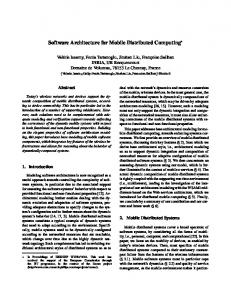
MR systems are usually sensor driven and so the software architecture is based on data flow. Figure 1 shows this data flow from an overall perspective with sensor data arriving into the MR system, being processed by specific application code and configurations, and then rendering the final output to the HMD of the user. The data flow model is supported by the use of objects to perform specific actions such as processing tracker data, combining results, and rendering 3D graphics. Objects allow problems to be broken down into small separate tasks to simplify software development. Objects are then connected together into a directed graph, and as new values enter the system, the values are processed through the graph as a flow of data, adjusting the current state and eventually rendering to the HMD. These objects can be distributed across multiple processes or computers in units named execution containers, with the data flow occurring over a network when required. Research toolkits are designed using many different methodologies and are difficult to use together because of conflicting requirements that may be difficult to address. In the future these may become standardised but for now we avoid trying to make immature and opposing toolkits work directly together so that research can be performed into new ways of developing software. All the components of the architecture are developed from
Sensors
Tinmith-evo5 Application Code
HMD
Runtime Config
Figure 1 - Overall architecture - sensors are processed using libraries and application components, then rendered to the HMD
Figure 2 - User outdoors manipulating a virtual table using AR
In ISMAR2003, International Symposium on Mixed and Augmented Reality Oct 7 - 10, 2003 - Tokyo, Japan - Copyright (C) 2003 IEEE Please visit http://www.tinmith.net for more information
the ground up using a common methodology, with abstractions to hide away any differences from external libraries that are required. The goal is to not to treat the application as a combination of scene graph, tracking library, and shared memory, but instead as a single entity with blurred boundaries. As part of the integrated component design methodology, the entire system has been structured around the model of a memory based file system. Instead of using global variables to reference the many objects available in the system, an object storage system based on Unix file system semantics provides a logical interface that is easy to understand. All objects that process data in the system are stored in this object repository, making them accessible to other objects in the system through discovery at run time. The ability to perform distribution across multiple computers is added as an extra component using object data flow, and is not an internal part of the architecture that imposes a constant performance penalty whether in use or not. The most important goal with the design of this software architecture is performance. Due to limitations in wearable computer hardware, it is important that as much work as possible be extracted out of the resources available. The C++ language and optimising compilers are used for all development, supporting both low level code and high level features such as objectoriented programming. The renderer that forms a core component of most applications is implemented using OpenGL and provides high performance graphics support when 3D acceleration hardware is present in the system. The software has been used on a number of small and relatively slow computers and is capable of running adequately in most cases, the exception being the rendering of large 3D scenes. This software architecture addresses a number of problems currently affecting mobile AR and similar environments: • Hardware changes rapidly over time, and so should be abstracted to allow portability across different environments. • Mobile AR is limited by portability constraints and choices must be made between large and powerful or small and less capable equipment. Software for outdoor use must be efficiently designed and be able to run on mobile hardware that may be a number of generations behind current state of the art indoor computers. • 3D graphics systems traditionally operate using a flat Earth model and do not readily deal with large areas of the planet that can be roamed with a mobile AR system. Being able to handle coordinates that span a wide range of scales, from millimetre level tracking of the hands to moving over hundreds of kilometres of land is required. • User interfaces for mobile AR are quite primitive and there is limited toolkit support for developing applications. This problem is difficult to solve and current development in this area is quite immature. This paper contains a summary of previous work, describing existing systems and their features. The design of the architecture is then described, including concepts such as data flow and object distribution. The object storage system forms a core part of the architecture and is described in the following section. The next section describes the more interesting aspects of the implementation of the software. Since processing input is a major part of the architecture, a section describes the model used to
abstract input events. The next section describes various examples demonstrating the usefulness of the software architecture, followed by a conclusion.
2 Previous work This section discusses a number of both low and high level toolkits that have been developed to help implement VE applications efficiently. We are interested in software architectures to support 3D mobile AR and not in areas such as wearable context awareness or other high level information sharing. There are a number of areas that need to be addressed, such as data distribution, rendering, user interaction, tracker abstractions, and rapid prototyping.
2.1 Hardware abstraction libraries Abstracting hardware presents a common programming model so applications only need to be written once to work with many devices. Most operating systems provide these abstractions for keyboards and mice and other researchers identified the need to have similar abstractions in 3D environments, and so implemented software such as the MR Toolkit [31] and VRPN [35]. Both of these systems are capable of processing trackers, distributing them over a network, and support many types of devices. Similar toolkits have been developed recently such as MAVERICK [12], VrJuggler [3], DIVERSE [16], and OpenTracker [25]. Each of these systems provides an inner kernel that connects together various components such as input abstractions for trackers, support code for processing data, and abstractions to rendering systems.
2.2 Distributed entity systems One area of investigation is the implementation of distributed virtual environments. This involves simulating entities on machines and then viewing them on remote clients over a network. The main focus of this research is on the protocols rather than the toolkits, such as SIMNET [6] and NPSNET [41] which use protocols similar to DIS [13]. These protocols usually only send 6DOF and entity information and the application is responsible for the models and rendering. These restrictions allow efficient scaling to large sizes. The Bamboo system [39] uses network loadable modules to support extensible protocols. BARS [5] uses an event based distribution mechanism to support mobile collaboration.
2.3 Software systems A number of software systems have been implemented to provide abstractions for other requirements apart from just trackers. Two early commercial toolkits were dVS [10] and World Toolkit [30]. These both provide tracking abstractions along with scene graphs, event triggering, and task distribution across machines. SGI has developed two powerful scene graph libraries based on OpenGL, IRIS Performer [26] and Open Inventor [33]. Similar scene graphs such as Java3D [34] and Repo-3D [18] are available for Java and Modula-3. Languages such as VRML 2.0 [38] have been develop to store scene graph definitions, and also include features such as fields and routes for developing interactive applications. Objects in VRML contain fields with values such as centre point, radius, and other geometry values. These fields can be controlled by
output fields from other objects, or used to control other objects. Using a route command, inputs and outputs can be connected and used to build complex flows of data in 3D models. Lightning [4] performs similar flow of data between objects, VB2 [9] use a constraint engine to implement relationships between objects in virtual environments, and DWARF [1] uses a services based framework to connect components over a network. High level authoring tools such as ALICE [20] allow novice users to implement simple VE applications using a scripting language, but is limited to the existing interactions supplied with the system.
2.4 Fully distributed systems While the previous systems only distribute small parts of the internal state, these systems perform more complete distribution of applications and scene graphs. The aim of the Tinmith-evo5 architecture is to provide a high level architecture similar to those discussed here. Coterie [17] was developed as a high level 3D toolkit and a more complete solution than just tracking abstraction. The main contribution is the modification of language level primitives to support the implementation of a distributed shared memory. This is integrated with packages that support an in-built interpreted language, threaded processing, tracker abstractions, animation, and a scene graph Repo-3D [18]. Multiple threads in the system execute code within objects and communicate via distributed shared memory. The Studierstube system [28] is a framework for distributed 3D applications. It is based on a tracker abstraction [25], and a distributed version of Open Inventor [11]. The distributed scene graph allows various applications to transparently share the same 3D environment with real time updates. Studierstube takes the opposite approach to Coterie and embeds the entire application into a distributed scene graph, and this has been used to demonstrate application migration between separate machines [29]. Studierstube applications must be implemented using Inventor objects to be supported in this way however. Systems such as DIVE [7] and Avocado [37] also support distributed scene graphs. DIVE uses multicast to improve scalability and reduce bandwidth usage. Avocado provides similar features as VRML fields and routes, with objects attached to each other and processed using a scripting language.
Application Implementation
Tracker devices
Tinmith-Metro, Custom models and menus
USB, Serial, PS/2
Application Support
Hardware abstraction
Menu driver, Event handler, Dialogs, Selections
Convert data into object
3D / 2D Render
Process object data flow
Scene graph, CSG ops, Manipulation
Conversions, state machines
Interface / Transform
Scene graph
Coordinate systems, Trackers, Transformations
Modify objects, CSG interactions
Low Level & I/O
Render
Support code, Callbacks, Serialisation, I/O libs
3D objects plus 2D overlay
Figure 3 – Layers of libraries with objects available to process data
Figure 4 - Expanded view showing stages of processing
3 Object design This section describes the overall design of the classes in the software architecture. Class definitions used in the software architecture can be divided into four categories - those for representing data values (data), those for processing input values and then producing some kind of output values (processing), those for implementing core features that other classes can inherit or use (core), and helper code that implements interfaces to streamline development (helper). Each class can also be classified into one of the categories depicted in Figure 3. Applications require classes from both high and low levels to be instantiated as objects and connected together. Each class can contain nested subobjects of other class types or primitive C++ values such as pointers, floats, integers, and strings.
3.1 Data flow Data objects in the system are used to supply input for processing objects. Processing objects then produce another data object that can then be propagated onwards for further operations. These connections form a flow of data through the system. Figure 4 depicts how data values initially arrive as tracker inputs, and are then processed in various stages of a virtual pipeline before reaching the user in the form of rendered output. This figure depicts categories for the objects used in various stages of the pipeline, but is only an approximate model. The data flow model is implemented by having processing objects listen to events that are generated by data objects. When the data object changes to a new value, interested listening objects are notified of this change via callbacks. This is similar to the observer/observable pattern described by Gamma et al [8]. Any number of processing objects can listen in on a data value, and processing objects can have any number of output values. The use of data flow is common in many of the previous systems described.
3.2 Serialisation and distribution Objects in the system are represented using the C++ compiler’s native internal format. It is not possible to simply take the binary data for the object and directly save it to disk or transport it across a network since it is specific to the running process only. The ability to save the state of a running system and then restart it at a later time or transfer it to another machine is desirable, and so a generic format that can represent application state is required. Serialisation is not available in C++ by default and so extra logic is provided to handle this requirement (the implementation details are discussed later). A structured XML format is used by default, with a binary format used to reduce the size of the data when required. Nested objects are processed by recursively calling the serialisation code and the results are assembled together for the top level object. The first use for a serialisation capability is to store persistent configurations on disk. The XML header is parsed to determine the object type, matching C++ objects are instantiated, and are configured to contain the values in the XML data. When the application is shut down these objects may be serialised back to disk so that it can resume its previous state at a later time. The serialised XML files may be used as a configuration system, and can be edited with a text editor or stored in a database. These
(1) Single Process / Single CPU (Default) Callback Function Call
Source
Listener
(2) Multiple Processes / Distributed On Network
Source
Tx
Net
Rx
Listener
Figure 5 - Network distribution is implemented transparently using automatically generated serialisation callbacks
objects can also be modified and reparsed at run time to adjust the application while in operation. This allows changing aspects of the application without having to resort to slower interpreted language support. While internal components such as network and disk interfaces cannot be serialised in this fashion, the parts of the application that a user would like to change are supported. Similarly, OpenTracker uses XML based configurations for filter graphs [25], VR Juggler uses text files for tracker reconfiguration [15], and Diverse uses compiled C++ modules switchable at run time [16]. This serialisation capability may also be used to implement distributed applications. An important feature is that the system does not force the user to use this capability. In most cases, applications are implemented as single processes and interactions between objects occur using simple function call based callbacks. The overhead of supporting the callback updates is very minimal when only local data is used. In contrast, many other systems require the application to use IPC interfaces even when operations are being performed locally, taking its toll as a large penalty on performance. Figure 5 part (1) depicts two objects that are connected via callbacks and so the listener is notified when the source signals a change has been made. Figure 5 part (2) depicts how objects can be inserted to implement distribution. When the source generates a new value, the Tx object serialises the new value and then transmits it over a network or other IPC mechanism. The Rx object at the destination receives the incoming data, deserialises it in place using the same class and then signals to the listeners of the object that new data is available. The listener object then receives a callback in the same way as in Figure 5 part (1). This distribution mechanism is transparent to the listening objects since it is implemented using the same interfaces as any other processing object. The object store described later automatically provides network distribution when required so that the programmer does not need to implement this functionality. The mechanism used for distribution (via callbacks and a possible network interface) is efficient because updates are only sent to those processing objects that are interested. Each object is stored on a particular server and other clients can make requests to receive updates when changes are made. For small systems, this is more efficient than broadcast protocols, although for large systems with thousands of processes each requiring a value this may not be appropriate. By using proxy processes, cached copies of values may be further distributed to others, which can assist with scaling. If a client needs to change the master value, the server must be configured to circularly listen for events from the client, or allow updates to be forced in via
the network command interface (described later in this chapter). Any changes forced in by the client will be lost by the server when the next incoming value arrives from the source, so this method is only practical when the value is no longer updating.
4 Object storage Systems containing many interoperating objects require techniques to organise this complexity. This section introduces the storing of objects based on the familiar Unix file system.
4.1 Unix file system design The Unix operating system (and clones) implements a hierarchical file system to organise and store data [19]. File systems provide an abstraction to simplify the storage of data on a disk that is otherwise just a raw linear collection of fixed size blocks (typically 512 bytes). Files can easily exceed the block size and so higher level abstractions are required for storage. An inode contains information about a file on a disk as well as a list of ordered pointers to blocks containing data. Each inode contains a unique identifier and is stored in a list at a fixed location on the disk. Directory structures were developed to store mappings between human readable text names and numeric inode values. Directories are also stored using inodes and have an associated unique identifier. Since both directories and files are represented using inodes, directories can provide text names for other directory inodes and so form a hierarchical tree structure. A top level root inode (with identifier 0) is used to represent the root directory (/) of the structure. Nodes in the tree can be accessed by specifying the name of each directory joined together using forward slash (/) characters. Path names that begin with a / character are referred to as absolute paths and are relative to the top level root node. Other path names starting with a name are referred to as relative paths and are accessed from the current working directory. Paths may contain aliases that have special meaning – the name . (single dot) is a relative reference to the current directory, while .. (two dots) is a relative reference to the parent of the current directory. Each file and directory is named relative to its parent and the full absolute path name is not stored anywhere. This allows changes at the top level to be instantly inherited by all children. Unix file systems implement hard links, multiple directory entries referencing a single inode value. This allows the same file to appear to exist in multiple locations but in fact is using a single set of blocks on disk. Modifications to one file will immediately affect others. Inodes store reference counts so that the disk blocks are not removed until there are no more references. A second link type named a symbolic link is used to provide a path name based link to another file. Directory entries can store mappings between names and inodes, and also names and other path names. When the kernel encounters a symbolic link it performs a lookup of the link name to find the appropriate inode and then resumes the previous lookup in progress. Since symbolic links point to paths and not inodes, a destination file can be replaced and all links to it will update automatically. Hard links require each link to be changed since the inode number of the new file is different.
4.2 Object file systems One problem with systems that store large collections of objects is accessing and updating them; the traditional approach being the use of global variables. Each module that needs to reference other objects must include definitions for the global variables, and suitable names must be used to avoid namespace collisions. Having global objects requires the compiler to statically declare these in advance, and hence cannot be changed at run time to suit conditions. To overcome this problem, systems such as dVS [10] and COTERIE [17] implement the concept of a repository where objects can be stored for later retrieval based on a key. The Windows operating system also implements a registry, which is a hierarchical database of values stored on disk and used to configure the operation of the system from a central location. These runtime style storage systems can be modified without recompilation to store a variety of values, and do not require statically declared objects. Programmers may independently write modules and are only required to agree on the naming convention to reference the shared objects. Referencing items stored within object-oriented databases has also been implemented previously using query languages such as XML’s XPath. XPath allows for the searching of objects meeting some kind of criteria (similar to SQL and relational databases), but was not intended to be for exact references like the Unix file system model. Tinmith-evo5 integrates a number of concepts to develop a hierarchical object store. Instantiated objects in the system are created in memory (statically by the compiler, or dynamically at run time) and then a pointer reference is placed into the object store. Rather than just implementing a hash of names to retrieve object pointers, the object store is based around the Unix file system model described earlier. Path names are used to traverse a tree of directories and files, and the inode values no longer point to lists of blocks but are instead pointers to memory addresses. These memory addresses are the locations of objects and method calls can then be made just like with any C++ object. Figure 6 depicts code fragments that demonstrate the storage of objects, retrieval and modification, and debugging. On the surface, this file system approach appears to give similar results to those achieved with other systems using names to lookup objects. The real advantages are gained when the Unix file system model is taken to its full extent to provide a number of interesting features. Hard links may be implemented by having multiple locations in the hierarchy point to the same object address. This allows code to use new naming conventions while still supporting older names for legacy source code. Symbolic links can be implemented by storing a path name redirection, so when the object store is traversing the internal structures it will recursively lookup the linked path names. Symbolic links implement much of the same functionality of hard links, but may also be used to provide dynamic switching of objects. For example, if a system contains both GPS (at /human/body/gps) and vision tracking (at /human/body/camera), then a symbolic link can be created at /human/body/tracking that points to the currently active tracker. The true source of input devices may be concealed from the developer using symbolic links as an abstraction layer.
/* Create object and store at an absolute path */ Position *pos = new Position (); pos->setStorage (“/human/body/position”); /* Code that changes the position value with a new LLH position update */ CoordLLH newllh; Position *update = Position::getStorage (“/human/body/position”); update->set (&newllh);
Figure 6 - Examples showing the hierarchical object store in use
During the implementation, we added several optimisations to reduce memory consumption and unnecessary lookups, and this resulted in the final version diverging slightly from the Unix file system model. Copy links are similar to hard links but do not actually share the same object pointer. Instead, a copy of the object is made for the link destination, and whenever the source is changed the object store copies the new updates into the destination object using data flow. The reverse is not true however, and if the destination is modified it is not copied back. These links were implemented using a copy since the object itself actually contains its own name and parent pointer. This prevents multiple names sharing the same object pointer but makes it possible for an object to quickly find its parent without having to traverse from the root node. Pointer links are the same as Unix based symbolic links in that they store a path name redirection in the object store.
4.3 Object hierarchies In object-oriented languages like C++, objects may be contained inside other objects, and this is referred to as composition. Figure 7 depicts the design of an object for storing position on the Earth. The example contains both grid (UTM) and spherical (LLH) coordinates and keeps the values synchronised using internal data flow processing. To gain access to the internal LLH and UTM values, external code may reference these directly if declared public or using access methods if declared private. Using the object store described previously and the example in Figure 6, the Position object could be stored at the path /human/body/position. To retrieve a pointer to this object the call Position::getStorage(“/human/body/position”) is used. Using standard C++, pointer->getLLH() or pointer->llh can be used to access the spherical LLH values. When using a file system based object store, it is also logical to store references to the child objects at sub paths to the parent. The spherical LLH child object can therefore be accessed directly using the call CoordLLH::getStorage(“/human/body/position/llh”). Both the parent and child objects are referenced in separate parts of the file system tree, but still remain joined together as a single object and so are still accessible to traditionally written code. The other /* Simple angle values */ class Angle { double degrees; }; /* Simple distance values */ class Distance { double metres; }; /* For spherical Earth coords */ class CoordLLH { Angle latitude; Angle longitude; Distance altitude; };
/* For grid based Earth coords */ class CoordUTM { Distance eastings; Distance northings; Distance altitude; int zone; char letter; }; /* Container for LLH and UTM values */ class Position { CoordLLH llh; CoordUTM utm;
};
CoordUTM &getLLH() { return (llh); }; CoordLLH &getUTM() { return (utm); };
Figure 7 - Simplified composite Position class with nested objects
advantage to this scheme is that since the file system is dynamic and can be traversed, child objects may be added or removed at run time (not just at compilation), and accessed without statically compiled names. Code can discover and access the contents of objects easily, allowing the writing of very generic code. Given a Position object, the call pointer->getNode(“llh”) can be used to dynamically retrieve the LLH child object from the parent. While objects added at run time are not visible to standard C++ code, dynamic access, serialisation, and callbacks are fully supported. Many OO based languages implement containers to store objects based on a key: C++ implements STL hashmap, Java implements HashMap, and SmallTalk implements Dictionaries. Some systems have been implemented that use containers to implement hierarchical structures of stored objects. An alternate implementation is to use the entire path as a single key, but this is not hierarchical storage. All of these implementation are different from our object store because they only store pointers to an object but do not handle the child objects contained within. Languages such as Java and SmallTalk support the run time discovery of child objects but the use of a consistent file system approach for all levels of the hierarchy is not performed. The file system approach is even more useful in languages such as C++, where run time discovery is not normally available.
5 Implementation internals The Tinmith-evo5 architecture is implemented in C++ to allow for an efficient implementation of the software. There is very limited run time support (avoiding features such as garbage collection) to hinder performance and compilers can generate optimised code, making it ideal for machines with limited resources. The C++ language does not provide some of the features needed for the implementation of the desired software architecture, so extra code is supplied to provide these. This section describes some internal implementation details.
5.1 Class definition and code generation C++ is a statically compiled language that provides objectoriented programming with inheritance, support for templates, and a macro pre-processor. Each object that is a part of the software architecture is required to inherit the abstract class Storable to provide interfaces that the object store and serialisation components require. A custom developed code generator TCC is used to generate internal information for each object. The Storable class uses this generated information to provide the discovery of internal objects, with the standard C++ RTTI functionality being too limited to use. A sample C++ object for an InterSense IS-300 tracker is demonstrated in Figure 8, with object and method declarations depicted. Special wrapper macros are used to indicate callback functions and internal variables that should be processed. These macros pass through during C++ compilation but are used by TCC to easily find the desired values without having to write a full C++ parser (although this could be avoided with more effort). The code generation is performed automatically because it is tedious and error prone for humans to do this by hand. When internal changes are made, TCC is used to regenerate the derived code in a separate file which is hidden from the programmer. Separate definition files
(such as used by CORBA and SUN RPC) are not transparent and require the programmer to keep the definitions synchronised with the implemented source code. Figure 8 depicts statically compiled methods such as getOrientation() and getMatrix() that are used to access internal values in the object. Inheriting the Orientationable and Matrixable interfaces in the class implements polymorphism and the use of the class as a generic tracker. The internal Storable methods getVarList(), getVarType(), and getVarPointer() are used for the run time discovery of object contents, providing similar functionality to SmallTalk and Java. The getNode(“name”) method is implemented by Storable and can be used to traverse to children objects, and is also used by the object store. The use of these method calls does add small overheads for lookup against internal object tables, but only has to be used when static references are not possible. This object discovery mechanism is used to automatically implement serialisation functions. Storable implements toXml() and fromXml() methods that can write out objects in an XML format that is human and machine readable. An alternate format is with the toBinary() and fromBinary() methods that use a compact binary representation in an endian neutral format. An important limitation of serialisation is that it cannot handle process specific values such as file descriptors or graphical handles, and so these must be implemented using manually written code.
5.2 Callback propagation The data flow model described previously is implemented using pointer based method callbacks. Instead of statically defining specific methods to be called when an event occurs, a pointer to any method defined with GEN_CALLBACK_H may be used. A single callback may listen to a number of event sources and a pointer to the modified object is passed as an argument to delimit between many objects. These callbacks are simple and efficient to perform since they involve a pointer dereference and then a function call, which is only slightly more overhead than using static function calls. When a callback is attached to an object, it will be notified whenever the object or any of its children are changed. When an object is modified it will execute the handlers attached at that level of the object store, and then work up the hierarchy of the object store executing handlers until it finds an object that is not contained within a parent object. The execution of callbacks is automatically implemented for copy and set operations using C++ operator overloading, so the programmer does not need to be aware of this mechanism. For objects containing internal class IS300 : public Storable, public Orientationable, public Matrixable { #define STORABLE_CLASS IS300 // Declare class name #include “interface/storable-generic.h” // Include customised template code public: // Declare callback using macro wrapper GEN_CALLBACK_H (IS300, process_device, IOdevice, _dev); Orientation IS300tracker Matrix RateTimer
*getOrientation (void); *getIS300tracker (void); *getMatrix (void); *getRateTimer (void);
IS300 (IOdevice *in_dev = NULL); private: IOdevice *device; TCC_OBJ TCC_OBJ TCC_OBJ TCC_VAR
(Orientation, (IS300tracker, (RateTimer, (double,
// // // //
Implement orientationable interface Access custom IS300 values Implement matrixable interface Implement statistics interface
// Constructor with input I/O source // Process dependent variables // Device pointer, not serialised by TCC
ori); is300); rt); value);
// // // //
Serialised orientation object Serialise IS300 values Serialise statistics information Serialise C double value
};
Figure 8 - Edited extract from the is-300.h tracker definition file
C++ values, these must be stored privately and wrapper methods written that generate callbacks. Figure 9 is a code fragment depicting how callbacks can be configured and then executed. The first set of code retrieves an object pointer from the object store and then uses the setHandler method to specify the callback method. The second set of code uses access methods to modify the internal values individually. The disadvantage to updating in this way is that callbacks are propagated for each modification and there is no way to indicate to the system that changes may be performed as a single unit (the programmer never calls an update method). The faster and preferred method depicted in the third set of code is to declare a new temporary object and initialise the values to those desired. The temporary object does not generate callbacks during initialisation, the data is copied using an overloaded equals (=) operator, and only a single callback is executed for the entire copy. Temporary objects are used in tracker abstractions to read incoming data, with only the latest version being copied over. This reduces the amount of callback traffic in the system and helps to improve performance. The callback system and the object store are tightly integrated, with callbacks being propagated up the tree until a top level container object such as /devices/trackers/gps is discovered. The path /devices/trackers is simply a set of empty paths used to contain objects and does not implement any object interfaces as such. This propagation of callbacks to parent objects is useful for when objects need to listen on areas of the object store but do not want to attach to individual objects since they may be transient. An example is an object listening on the entire scene graph for changes to distribute to other machines.
5.3 Distributed processing In most applications, a single non-threaded process is used as an execution container for objects to be connected together via data flow and callbacks. It may however be desired in some cases to distribute the application across separate processes running on a number of computers. Objects are placed into execution containers (Unix processes, not threads) and connected together using the network distribution technique described previously. Each execution container has its own memory and code, and may contain internal threads although these are discouraged. The communication within an execution container is performed using local callbacks, but these do not work across containers in different address spaces. The network distribution mechanism described previously is used to connect together execution containers so that they can communicate with each other. Each execution container implements a NetServer object that listens for incoming connections. Clients connect to the server and make requests to listen to particular object paths. The NetServer object attaches itself to these objects in the object store, and when they change the NetServer will be notified. When the notify callback is executed, the NetServer object takes the updated object pointer and serialises it into XML or binary format depending on the client’s request. The client receives this stream of data and then deserialises it into an equivalent matching object created previously and stored locally. When the value is copied into the local object, other processing objects that are
listening to this local object will receive a newly generated callback and the data flow process continues. With this mechanism objects can be easily separated into arbitrary execution containers. When updates are made in large trees such as the scene graph, the amount of data generated can be quite large although there are only a small number of changes. The XML format allows differences to be sent that only contain the changed data. Each object records an incrementing serial number to keep track of the last object version sent so the server can send correct differences to the interested clients. Since the binary protocol is a fixed format it does not support varying differences. The type of protocol used also affects the choice of network transport. UDP is high speed, connectionless, has a 64kb packet length, possible loss of packets, and may arrive out of order. TCP is slower, maintains a connection, has virtually unlimited transmission sizes, and guaranteed transmission of data. UDP with binary mode may be used for absolute updates where lost packets do not need to be recovered, such as head trackers. TCP with XML is used for communicating with the server and testing for connectivity, and for data that cannot be lost, such as object differences of scene graph updates. The requesting client can specify the format to use during the connection setup, and can switch protocols if needed. An object inside a server execution container is owned and updated by that container exclusively. The execution container makes this object available for other objects (both local and remote) to receive updates for further processing. The data flow approach can support circular flows of data, but is generally avoided unless one of the objects contains a mechanism to end processing and not continually propagate in an infinite loop. Alternatively a client can connect in and upload a new value for the server to store, and it will remain until replaced by whatever source originally generated it in the server. Uploading values is not generally used but can be used to control internal values of an application such as user interface controls that are only periodically changed.
5.4 Threads In most cases, execution containers do not require the use of threads to perform their processing of data flows. Data flow calculations tend to be very sequential and most libraries implement thread safety using a single lock, forcing most operations to run exclusively. Since the display depends on all calculations being completed it must be performed last and so cannot be run in parallel. While some calculations may be parallelised, the benefit is small considering the added costs of context switching and the complexity of implementing multi threaded libraries using locking. The programming model is therefore designed around the use of a single thread of control within an /* Find source object and attach destination callback to listen for changes */ Position *source_position = Position::getStorage (“/devices/trackers/gps/pos”); source_position->setHandler (dest_position->process_position); /* Make changes to source value – 3 separate callbacks generated */ source_position->setLatitude (138.00); source_position->setLongitude (34.00); source_position->setAltitude (0.0); /* Make changes to source value – efficient single callback */ Position temp (138.00, 34.00, 0.0); *source_position = temp;
Figure 9 - Code demonstrating setup and execution of callbacks
execution container to simplify the design of the system. While many calculations complete quickly, others such as video capture and vision tracking (as used in Tinmith-Metro) require longer periods of time. Separate execution containers are preferable, but in Tinmith-Metro the video frames must be available to the renderer and IPC is too resource intensive so a thread is used. Since the object store is not thread safe, a special communications mechanism using simple locking primitives is implemented to pass the video frame to the main thread.
5.5 Operating system interface The data flow model used by the software architecture is not supported directly by any operating system and so a suitable abstraction layer is required. POSIX compliant operating systems generally provide a file based interface to all devices in the system, with open(), read(), write(), ioctl(), and close() system calls. A generic set of classes are provided to interface to these calls for devices such as serial ports, disk files, TCP sockets, UDP sockets, and generic file descriptors. The global I/O manager object keeps track of all file descriptors in use and generates data flow events when they become ready for reading or writing. Non-blocking I/O is used with a select() processing loop to allow a single thread to process many I/O sources and time outs simultaneously. This is in contrast to languages such as Java where programmers are encouraged to use a thread for each blocking I/O device, increasing overheads and requiring thread synchronisation. The I/O manager developed for this software architecture is similar to the concept of a kernel used in DIVERSE [16] and VR Juggler [3]. The software is portable across platforms and currently runs on Linux and FreeBSD systems, as well as Windows using the Cygwin libraries. Rendering to the display is performed using OpenGL graphics under X Windows. When running on a local server, the OpenGL graphics rendering is performed directly to the hardware using Direct Rendering Extensions (DRI). The X Windows server is used to provide window handling and the management of events from the keyboard and mouse.
6 Sensors and events Tinmith-evo5 processes incoming sensors and events using a set of abstraction models and representation formats appropriate for the type of input data. It has been designed mainly for input devices used in typical mobile AR applications.
6.1 Tracking devices Tracking devices return a number of degrees of freedom, with either position or orientation or both depending on the technology being used. Some of these results may be absolute in that the values may be relative to the Earth’s coordinate system, while others return their results relative to the coordinate system of another device. These distinctions are used to categorise trackers into four separate classes: Position, Orientation, PositionOffset, and OrientationOffset. Each of these classes represents 3DOF information, and for devices that produce less DOFs some of the values will be set to a constant value. For 6DOF trackers the result will be split across both an orientation and a position class. Each class contains a number of different formats internally, and by adjusting one the data flow model is used to recalculate the other values automatically.
The Position class is used to represent objects stored relative to the Earth [14]. This class implements storage of values in polar coordinates (LLH - latitude, longitude, height), Earth centred (ECEF - metres from the centre), and grid coordinates (UTM - metres relative to flat zones on the Earth). The GPS inputs are normally mapped to LLH inputs, while the OpenGL rendering is performed using the grid based UTM system. UTM coordinates are expressed relative to a local origin although in most cases will be millions of metres away. If OpenGL is presented with these values directly, it will exceed the internal range of the transformation matrices and fine objects near the user will jitter and deform. The Position class implements a fourth coordinate system based on UTM, but with all coordinates relative to a movable local anchor point. The local anchor reduces the range of floating point values and performs rendering of millimetre accurate objects (such as the hand tracker) correctly. The PositionOffset class represents relative position change from an absolute position in UTM surface XYZ coordinates as well as a matrix format. Indoor trackers as well as 2D desktop mice use PositionOffset. Orientation values are specified relative to the local UTM surface. While Euler angles can be used to specify orientation they suffer from known Gimbal lock problems and so 4x4 matrices can also be used. A third method named Aerospace angles are used based on heading, pitch, and roll values that mimic those used to express aircraft orientation. The use of three angles is used by many common tracking devices that generate absolute orientation. Similar to previously, an OrientationOffset class represents relative orientation change from an absolute orientation. These values are stored using 4x4 Matrix values only since Euler and Aerospace angles are difficult to correctly combine.
6.2 Filters Incoming tracker data usually requires some processing before it can be presented to the scene graph or other data flow objects for operations. Using the data flow model operations such as filtering, combining degrees of freedom from multiple trackers, conversions between coordinate systems, and performing mathematical operations can be performed. This is similar to that performed by OpenTracker [25]. The various 3DOF classes can be combined using matrix multiplication to form complex articulated calculations if desired. While this combination can be performed using processing objects it is difficult to visualise and so the next section discusses the use of the scene graph to perform calculations instead.
6.3 Input devices Discrete events are handled differently in the data flow model due to their non-continuous nature. There are a number of types of button presses to handle, some examples being mouse buttons, keyboard buttons, and glove pinches. All inputs are described using a keyboard model, where the object stores an identifier for the last button activated with a press or release action. The identifier may be either an ASCII character code or an extended enumerated value for mouse buttons or glove fingers. Processing objects may listen for input device events and receive notification when they occur. Callbacks must process each event as they arrive and multiple events are executed as individual callbacks. Devices such as keyboards map directly to
this model, while others such as mice are represented using a supplementary PositionOffset for motion. Since software development is performed on a desktop various tracking devices may not be available. Simulator objects are available that can generate artificial events for many stages of the data flow. For example, IOdevice simulators provide raw data to test parsers and Position simulators are used to test the user moving through the scene graph.
7 Demonstrations The software architecture has been used to implement a number of powerful applications such as the Tinmith-Metro modelling application [22] [24], simplifying development.
7.1 Scene graph A component of many applications based on the software architecture is a hierarchical scene graph system with a structure similar to that of Open Inventor [32] or SGI’s Performer [26], with 3D geometry controlled by transformation nodes. Primitive objects such as spheres, cones, cylinders, polygons, and triangle meshes are supported and are contained within grouping objects. Each object can contain transformations and levels in the scene graph map directly to path names in the object store. XML files with syntax similar to the X3D standard [40] are used to represent the scene graph during serialisation, and VRML and Inventor formats are also supported. An integrated part of the scene graph is a real time constructive solid geometry (CSG) object based on data flow. The CSG object is attached to two input nodes (which can be either single objects or entire hierarchies) and listens for changes when they occur. When an input object changes, the node performs the CSG operation on the two inputs and generates an output mesh that can then be rendered in the scene graph. The CSG engine is capable of operating in real time so that the user can manipulate the input objects and see the final output immediately. Performing transformations on tracker values directly can be time consuming and tedious and so scene graphs were developed to abstract away many of these tasks. By attaching tracking devices to transformation nodes, complex articulated models can be rendered with ease. Instead of using the scene graph just for rendering, we propose to use the scene graph as a calculation engine and extract values out of it after computations are performed (sometimes without rendering anything). The use of the scene graph means the results can be verified graphically by the programmer instead of dealing with equations directly. An example of these calculations in use is the processing of hand tracking in Tinmith-Metro [22] [24], and the implementation of an indoor ARToolKit based roof tracking system [23].
7.2 NFS server To demonstrate that the software architecture implements file system semantics, a Network File System (NFS) server object was written and integrated into our applications. NFS [27] was first introduced to provide remote file system capability over a network. Files on a server appear to be mounted directly on a client machine. NFS operates using Remote Procedure Calls (RPC) over UDP packets and defines procedures to support primitive file system operations lookup, create, remove, getattr, setattr, read, write, rename, link, symlink, readlink, mkdir,
rmdir, readdir, and statfs. As a user browses the file system the operating system’s virtual file system layer (VFS) generates RPC requests to the NFS server. The NFS server processes each request and generates a result with the required data. Our NFS server implements the same RPC requests but maps these to the object storage system. When the client requests information about a file the server traverses the object store and generates artificial information such as permissions, inode values, and sizes based on the contents of the object found and its type. Read requests on a virtual file will receive an XML or text representation of the object that is generated on the fly, and write operations can be used to modify the internals of an object in the server. This NFS server implementation allows interfacing to other legacy software using only simple file based I/O.
7.3 DIS protocol support Our original DIS protocol based collaboration work performed previously [21] has been rewritten for this software architecture except it is even more highly integrated and transparent. Entity state updates arriving from the network contain a unique set of identifier values to separate it from other entities such as site, host, and entity id values. Instead of having a separate internal list of objects, the scene graph is used to represent each entity at a path location such as /models/world/dis/siteid/hostid/entityid. As the position and orientation values are extracted from the DIS entity state PDU packet [13], they are converted into a 6DOF matrix and then pushed directly into the scene graph. This method treats the DIS update the same as a tracking device, with the numeric id values used to directly identify the correct place in the scene graph. Each entity can be represented using a 3D model for realistic rendering and updated in real time as packets arrive.
7.4 Low end hardware One of the goals of the software architecture was to be able to develop applications for a wide range of computers. Our high end platform is a Pentium-III laptop with a GeForce2 OpenGL accelerator, but low end hardware is much slower and less capable. We performed tests using an old Pentium-I embedded computer with no 3D acceleration to test the performance of the architecture. The ARQuake game [36] uses a driver program based on Tinmith-evo5 to generate UDP packets that control the 6DOF internal values in the game. The software architecture processes the sensors with minimal overheads, the Quake renderer using most of the processor. The full Tinmith-Metro application was also tested on this computer, but some changes were required in order to make the software run. The lack of 3D acceleration requires software emulation which is very slow and inefficient. Generating a single frame takes many seconds and so this is not useful as a real time AR system. We use a small open source emulation library called TinyGL [2] which provides basic OpenGL functionality but leaves out more complex features. This library is capable of providing 3D rendering with textures on very old computers and can generate a number of frames per second. The optical overlay mode was used to avoid processing the video streams since the hardware is not powerful enough.
8 Conclusion This paper has described the Tinmith-evo5 software architecture, explaining our integrated and uniform approach to building applications for mixed reality environments. The architecture uses a data flow methodology with an object-oriented design and using an object store based on Unix file system semantics to provide a simple model for programmers to use to write applications. Using these concepts, a number of powerful features such as distributed programming, persistent storage, and run time configuration are possible. The design is based on the C++ language and although the language has a number of limitations, these are overcome using a variety of techniques to develop efficient applications that operate on a wide range of mobile computers. The capabilities of this software architecture are demonstrated by the Tinmith-Metro mobile outdoor modelling application, as well as other examples presented in this paper.
9 References [1]
[2] [3]
[4] [5]
[6] [7] [8] [9] [10] [11]
[12]
[13] [14] [15]
[16]
Bauer, M., Bruegge, B., Klinker, G., MacWilliams, A., Reicher, T., Ris, S., Sandor, C., and Wagner, M. Design of a Component-Based Augmented Reality Framework. In 2nd Int'l Symposium on Augmented Reality, pp 4554, New York, NY, Oct 2001. Bellard, F. TinyGL version 0.4. http://fabrice.bellard.free.fr/TinyGL Bierbaum, A., Just, C., Hartling, P., Meinert, K., Baker, A., and Cruz-Neira, C. VR Juggler: A Virtual Platform for Virtual Reality Application Development. In IEEE Virtual Reality 2001, pp 89-96, Yokohama, Japan, Mar 2001. Blach, R., Landauer, J., Rosch, A., and Simon, A. A Highly Flexible Virtual Reality System. Future Generation Computer Systems, 1998. Brown, D., Julier, S., Baillot, Y., and Livingston, M. A. An Event-Based Data Distribution Mechanism for Collaborative Mobile Augmented Reality and Virtual Environments. In IEEE Virtual Reality 2003, Los Angeles, Ca, Mar 2003. Calvin, J., Dickens, A., Gaines, B., Metzger, P., Miller, D., and Owen, D. The SIMNET virtual world architecture. In IEEE VRAIS '93, pp 450-455, Sep 1993. Frecon, E. and Stenius, M. DIVE: A Scaleable Network Architecture For Distributed Virtual Environments. Distributed Systems Engineering Journal, Vol. 5, No. 3, pp 91-100, 1998. Gamma, E., Helm, R., Johnson, R., and Vlissides, J. Design Patterns: Elements of Reusable Object-Oriented Software. Reading, Ma, Addison Wesley Publishing Company, 1995. Gobbetti, E. and Balaguer, J.-F. VB2: An Architecture For Interaction In Synthetic Worlds. In 6th Int'l ACM Symposium on User Interface Software and Technology, pp 167-178, Atlanta, Ga, Nov 1993. Grimsdale, G. dVS - distributed virtual environment system. In Proc. Computer Graphics 1991 Conference, London, UK, 1991. Hesina, G., Schmalstieg, D., Fuhrmann, A., and Purgathofer, W. Distributed Open Inventor: A Practical Approach to Distributed 3D Graphics. In ACM Virtual Reality Software Technology, pp 74-81, London, UK, Dec 20-22, 1999. Hubbold, R., Cook, J., Keates, M., Gibson, S., Howard, T., Murta, A., West, A., and Pettifer, S. GNU/MAVERICK - A micro-kernel for largescale virtual environments. In ACM Virtual Reality Software Technology, pp 66-73, London, UK, Dec 1999. Institute of Electrical and Electronics Engineers. Protocols for Distributed Interactive Simulation. In ANSI/IEEE Standard 1278-1993, 1993. Intergovernmental Committee On Surveying and Mapping. Geocentric Datum of Australia - Technical Manual. http://www.anzlic.org.au/icsm/gdatm/index.html Just, C., Bierbaum, A., Hartling, P., Meinert, K., Cruz-Neira, C., and Baker, A. VjControl: An Advanced Configuration Management Tool for VR Juggler Applications. In IEEE Virtual Reality 2001, pp 97-104, Yokohama, Japan, Mar 2001. Kelso, J., Arsenault, L. E., Satterfield, S. G., and Kriz, R. D. DIVERSE: A Framework for Building Extensible and Reconfigurable Device Independent Virtual Environments. In IEEE Virtual Reality 2002, Orlando, Fl, Mar 2002.
[17] MacIntyre, B. and Feiner, S. Language-Level Support for Exploratory Programming of Distributed Virtual Environments. In 9th Int'l Symposium on User Interface Software and Technology, pp 83-94, Seattle, WA, Nov 1996. [18] MacIntyre, B. and Feiner, S. A Distributed 3D Graphics Library. In ACM SIGGRAPH 1998, pp 361-370, Orlando, Fl, Jul 1998. [19] McKusick, M. K., Bostic, K., Karels, M. J., and Quarterman, J. S. The Design and Implementation of the 4.4 BSD Operating System. 2nd ed, Addison-Wesley, 1996. [20] Pausch, R., et al. Alice: A rapid prototyping system for 3D graphics. IEEE Computer Graphics and Applications, Vol. 15, No. 3, pp 8-11, 1995. [21] Piekarski, W., Gunther, B., and Thomas, B. Integrating Virtual and Augmented Realities in an Outdoor Application. In 2nd Int'l Workshop on Augmented Reality, pp 45-54, San Francisco, Ca, Oct 1999. [22] Piekarski, W. and Thomas, B. H. Tinmith-Metro: New Outdoor Techniques for Creating City Models with an Augmented Reality Wearable Computer. In 5th Int'l Symposium on Wearable Computers, pp 31-38, Zurich, Switzerland, Oct 2001. [23] Piekarski, W., Avery, B., Thomas, B. H., and Malbezin, P. Hybrid Indoor and Outdoor Tracking for Mobile 3D Mixed Reality. In 2nd Int'l Symposium on Mixed and Augmented Reality, Tokyo, Japan, Oct 2003. [24] Piekarski, W. and Thomas, B. H. Interactive Augmented Reality Techniques for Construction at a Distance of 3D Geometry. In Immersive Projection Technology / Eurographics Virtual Environments, Zurich, Switzerland, May 2003. [25] Reitmayr, G. and Schmalstieg, D. An Open Software Architecture for Virtual Reality Interaction. In Virtual Reality Software Technology, Banff, Canada, Nov 2001. [26] Rohlf, J. and Helman, J. IRIS Performer: A High Performance Multiprocessing Toolkit for Real-Time 3D Graphics. In ACM SIGGRAPH 1994, Jul 1994. [27] Sandberg, R., Goldberg, D., Kleiman, S., Walsh, D., and Lyon, B. Design and Implementation of the Sun Network Filesystem. In Summer 1985 Usenix Conference, pp 119-130, Portland, Or, Jun 1985. [28] Schmalstieg, D., Fuhrmann, A., and Hesina, G. Bridging Multiple User Interface Dimensions with Augmented Reality. In 3rd Int'l Symposium on Augmented Reality, pp 20-29, Munich, Germany, Oct 2000. [29] Schmalstieg, D. and Hesina, G. Distributed applications for collaborative augmented reality. In IEEE Virtual Reality, pp 59-66, Orlando, Fl, Mar 2002. [30] Sense8 Incorporated. World Toolkit. http://www.sense8.com [31] Shaw, C., Green, M., Liang, J., and Sun, Y. Decoupled Simulation in Virtual Reality with The MR Toolkit. ACM Transactions on Information Systems, Vol. 11, No. 3, pp 287-317, 1993. [32] Strauss, P. R. IRIS Inventor, A 3D Graphics Toolkit. In 8th Annual Conference on Object-oriented Programming Systems, pp 192-200, Washington, DC, Oct 1993. [33] Strauss, P. S. and Carey, R. An Object-Oriented 3D Graphics Toolkit. In ACM SIGGRAPH 1992, pp 341-349, Chicago, Illinois, Jul 1992. [34] Sun Microsystems. The Java3D API - Technical White Paper. Technical Report, Sun Microsystems, Jul 1997. [35] Taylor, R. M., Hudson, T. C., Seeger, A., Weber, H., Juliano, J., and Helser, A. T. VRPN: A Device-Independent, Network-Transparent VR Peripheral System. In ACM Virtual Reality Software Technology, pp 55-61, Banff, Canada, Nov 15-17, 2001. [36] Thomas, B., Close, B., Donoghue, J., Squires, J., De Bondi, P., Morris, M., and Piekarski, W. ARQuake: An Outdoor/Indoor Augmented Reality First Person Application. In 4th Int'l Symposium on Wearable Computers, pp 139-146, Atlanta, Ga, Oct 2000. [37] Tramberend, H. Avocado: A Distributed Virtual Reality Framework. In IEEE Virtual Reality 1999, pp 14-21, Houston, Tx, Mar 1999. [38] VRML Consortium Incorporated. The Virtual Reality Modeling Language. In ISO/IEC 14772-1:1997, 1997. [39] Watsen, K. and Zyda, M. Bamboo - A Portable System for Dynamically Extensible, Real-time, Networked, Virtual Environments. In IEEE Virtual Reality Annual International Symposium, Atlanta, Ga, Mar 1998. [40] Web3D Consortium. Extensible 3D (X3D) Draft Specification. In ISO/IEC FCD 19776-1:200x, 2002. [41] Zyda, M. J., Pratt, D. R., Monahan, J. G., and Wilson, K. P. NPSNET: Constructing a 3D virtual world. In 1992 ACM Symposium on Interactive 3D Graphics, pp 147-156, Cambridge, Ma, Mar 1992.