Sep 12, 2010 - engine; (d) to allow a high degree of customisation of the output of an extended ... This work presents CWSNet; a new software toolkit for water ...
Water Distribution System Analysis 2010 – WDSA2010, Tucson, AZ, USA, Sept. 12-15, 2010
CWSNet: An object-oriented toolkit for water distribution system simulations M. Guidolin, P. Burovskiy, Z. Kapelan, D.A. Savić Centre for Water Systems, College of Engineering, Mathematics and Physical Sciences , University of Exeter, North Park Road, Exeter, EX4 4QF, United Kingdom {M.Guidolin, P.Burovskiy, Z.Kapelan, D.Savic}@exeter.ac.uk
Abstract In the field of water distribution systems the EPANET 2 toolkit is considered nowadays the industry standard for hydraulic modelling. Unfortunately, the design and programming model of EPANET 2 have some limitations that make any attempt to extend its hydraulic solver, add new functionalities or improve performance difficult to achieve and time consuming. A new software toolkit for water distribution system modelling, CWSNet, is presented. CWSNet is developed in C++ using the object-oriented programming model. The aim is to deliver an open-source substitute for EPANET 2 that obtains numerically comparable results while providing similar or better performance, a higher degree of extensibility, as well as backward compatibility where possible. The idea behind this project is to simplify development and testing of new hydraulic elements (specific types of valves, pumps, etc) and computational algorithms (pressure-driven approaches, etc.) by keeping logically independent parts of the code separate. This also allows the performance and accuracy of new computational methods as well as the use of advanced programming techniques (multi-threading, OpenMP, GPGPU, etc) to be studied without the need for extensive code refactoring. The basic version of CWSNet gives numerically the same results as EPANET 2 for various networks while allowing the following: (a) to change the topology of the network at runtime; (b) to run different simulations of the same network or different networks in parallel (thread-safe); (c) to easily change the mathematical model and other particulars behind the hydraulic simulation engine; (d) to allow a high degree of customisation of the output of an extended period simulation. The CWSNet software capabilities are demonstrated using several examples. The results obtained demonstrate the effectiveness and efficiency of the proposed approach.
Keywords EPANET, CWSNet, C++, OOP, Open Source
1. INTRODUCTION The EPANET 2 toolkit (Rossman, 2000) is a powerful package used to solve many research and industrial problems in the field of water distribution systems. However, the hydraulic solver implemented in EPANET 2 has some restrictions that sometimes limit its usefulness in comparison to alternative contemporary hydraulic solvers. These include the lack of ability to model some physical elements which are often used in real-life water distribution networks, such as Variable Speed Pumps (VSPs), and the limitation of the demand-driven methodology which, in some cases, could produce negative pressures. Since the EPANET 2 toolkit is widely used and the code is freely available, a large amount of research has been done in order to resolve the restrictions of its hydraulic solver. Therefore, many upgrades and extensions have been developed for the toolkit and presented in various research papers. However, the internal structure of EPANET 2 and the programming model used to develop the toolkit have been designed and chosen to produce fast executions, but not to facilitate the understanding and the extension of the code. Therefore any attempts to expand the functionalities of EPANET 2 or improve its performance are difficult to achieve and time consuming. Furthermore, the disadvantages caused by the
Water Distribution System Analysis 2010 – WDSA2010, Tucson, AZ, USA, Sept. 12-15, 2010
code structure make any effort to merge the various presented extensions in a single package very hard to achieve. In the past, there have been various projects that aimed to improve the usability and extendibility of the EPANET 2 toolkit. Two examples are the OpenNet framework of Morley et al. (2000) and the OOTEN (Object Oriented Toolkit for EPANET) toolkit of van Zyl et al. (2003). These two projects implement an object-oriented layer over the EPANET 2 hydraulic solver, i.e. they use different classes in C++ for the various physical and logical elements of the water distribution system simulated. While this objectedoriented layer simplifies the access and the management of the elements and their attributes and thus allows more control over the network; the code of the hydraulic solver used is still the EPANET one. Therefore, all the disadvantages of the EPANET 2 code, which are derived from the internal structure and the programming model used, are generally also valid for these two projects. This work presents CWSNet; a new software toolkit for water distribution system modelling where all the various parts of the hydraulic modelling are completely developed in C++ using an object-oriented programming (OOP) model. The main aim of the CWSNet project is to deliver an open-source substitute for EPANET 2 that obtains numerically comparable results while providing similar or better performance, a higher degree of extensibility, as well as backward compatibility where possible. The need to obtain high performance in CWSNet comes from the fact that hydraulic solvers, in conjunction with optimisation algorithms, are commonly used to find the optimal solutions of water distribution system problems. Since the use of optimisation algorithms, such as genetic algorithms, requires hundreds of thousands of simulations, the performance of the hydraulic solver is critical. The research of a higher degree of extensibility is motivated by the need to improve 1) the numerical stability of the existing solver; 2) the ability to add and choose different hydraulic solvers that implement different methodologies, such as a pressure driven simulation; 3) the modelling of existing elements and the support of new hydraulic elements, such as VSPs; and 4) the possibility to develop and test new functionalities. Furthermore, the easy expansion of the code allows the testing and the implementation of new techniques that can improve the performance of the toolkit, such as multi-threading, OpenMP and general-purpose computing on graphics processing units (GPGPU). The idea behind the CWSNet project is to permit the easy implementation of these improvements and thus to make an effective toolkit freely available for research and commercial purpose. In order to achieve these objectives, the CWSNet code uses the advantages of the object-oriented programming model by representing the elements of the network, the computations on their attributes and the various computations of the hydraulic modelling as independent objects. Each one of these objects has its own well-defined interface that simplifies the reuse, modification, swapping and upgrade of the code. Furthermore, the internal structure of CWSNet is logically divided in three layers which facilitate the understanding of the code and thus the possibility to extend the functionalities of the toolkit. Given that one of the aims of CWSNet is to allow a user to choose between various different hydraulic solvers, in the future it will be important to specify the methodology used when referencing the CWSNet toolkit. However, in the current version of CWSNet, there is only one hydraulic solver available which implements the same methodology of the EPANET 2 hydraulic solver, a demand-driven global gradient algorithm (GGA) (Todini and Pilati, 1987). This implementation in CWSNet of a similar demand-driven hydraulic solver, together with the implementations of many of the functionalities of the EPANET 2 toolkit, has been done in order to achieve full backward compatibility. However, CWSNet has some extra features that are not available in EPANET 2:
Water Distribution System Analysis 2010 – WDSA2010, Tucson, AZ, USA, Sept. 12-15, 2010
•
The topology of the network can be changed at run-time. Thus a user can modify dynamically a network, such as removing and adding new elements, during an extended period simulation (EPS) without the necessity to start the execution from the very beginning.
•
It is possible to run different simulations of the same network, or different networks, in parallel (thread-safe). Each hydraulic simulation uses its own data environment, thanks to the OOP design. Thus, different simulations are completely independent.
•
The mathematical model and other particulars behind the hydraulic simulation engine can be changed easily. This allows customisation of the code that deals with matrix representation and the linear solver in order to tune up the computations according to the nature of the modelled problems.
•
There is a high degree of customisation of the output of an EPS. For example it is possible to keep the history of the values of each attribute and it is possible to dynamically change the unit of measure of each physical attribute.
In the following part of this paper, the CWSNet toolkit is presented in more details. In the next section, the reasons behind the difficulties in understanding and expanding the code of the EPANET 2 toolkit are presented. Then, the internal design of CWSNet is introduced and the composition of each layer of the internal structure is explained. The further sections deal with the status of the CWSNet project, the future extensions that are planned and the features that could allow CWSNet to achieve a high level of computational performance. In the final part of the paper, the numerical results and the execution times obtained in various example networks from the demand-driven hydraulic solver of CWSNet are compared to those obtained from the EPANET 2 toolkit in order to confirm that CWSNet can be an alternative to EPANET 2.
2. EPANET 2 ISSUES One of the major problems that a programmer faces in order to understand and update the EPANET 2 toolkit is that various parts of the code are highly optimised for performance and therefore they are too intricate and not well separated. The different elements of a network are represented through the use of specific structures. However, in order to save memory space, the majority of the elements share some common structures. This results in the same variable representing different attributes for different elements. This complicates the understanding of a variable’s role and use. Another problem is the abundant use of global variables in the code. This situation complicates the understanding of the behaviour of the various methods used in the code and the possibility of reusing them. Furthermore, the use of global variables limits the possibility of increasing the computational performance of the toolkit since the code becomes thread-unsafe, i.e. it is very difficult to divide the computation between different threads and thus it is not possible to take advantage of recent multi-core hardware. In the case of the internal design of the toolkit, one problem is that the various computations that are specific to the type of element considered are not well separated. For example, the reservoir’s elements share the same data structure as the tank’s elements, where the reservoirs are identified by having the volume attribute equal to zero. Thus, in order to identify the computation that is specific to a tank instead of a reservoir, a programmer needs to search for the conditional statement that checks the volume size. Another problem in the design of EPANET is that the items that are used in various parts of the hydraulic computation (such as the matrix representation) do not have a specific interface. For example, the matrix that represents the linear systems of equations is accessed directly by the various methods, i.e. these
Water Distribution System Analysis 2010 – WDSA2010, Tucson, AZ, USA, Sept. 12-15, 2010
methods know how the matrix is represented in the memory. Therefore, if a programmer needs to change the internal representation of the matrix, he or she needs to change all the methods that interact with it. The final issue of the EPANET toolkit, which is influenced by the problems previously introduced, is that the code does not manage dynamic changes in the data structure that represents the network topology. Therefore, in EPANET it is not possible to remove or add an element into the network during the execution of an EPS. In order to do so, a user has to load a network that already contains all the possible elements needed and then the network topology can be changed by modifying the elements’ status when necessary. This solution is not always trivial to implement, since the future modifications of a network topology are not always predictable, as could be in the case when they are produced by optimisation algorithms.
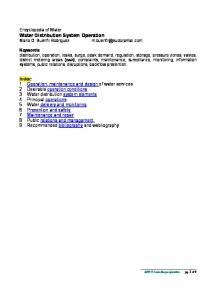
3. CWSNET DESIGN The internal structure of CWSNet is designed in order to facilitate the understanding of the code, the testing of new methods, the maintenance and update of the existing computations and the adding of new methodologies and new features. Figure 1 shows the internal structure of the toolkit which is divided in three layers: a network layer, a hydraulic solver layer and a mathematical layer. Each layer is composed of many objects. These objects can function as containers of data (such as the network object and the matrix representations object), as computational methods (such as the objects of the network interaction part and the linear solver object) or as flow control methods (such as the simulation object and the computational methodology object). The objects are all designed to have a well defined interface.
Figure 1 CWSNet internal structure
Water Distribution System Analysis 2010 – WDSA2010, Tucson, AZ, USA, Sept. 12-15, 2010
In order to execute an extended period simulation, a user will interact mainly with the objects of the first layer, while he or she can ignore the objects of the other layers. However during an EPS, the objects of the last two layers will execute the large bulk of the computations, while the objects of the first layer will be mainly used for storing and retrieving network data and for checking the flow of execution.
3.1 Network layer The first layer represents the part of the code that acts as an interface between the user and the hydraulic solver. The network layer allows a user to apply different types of problems to the same hydraulic network, such as different hydraulic simulations, or in future, different water quality analyses, reliability evaluations, etc. Furthermore, it also allows a user to apply easily the same problem to different hydraulic networks in order to optimise a characteristic of a water distribution system. The network layer is composed of mainly two items: the network object and the simulation object. A network object describes the topological network of a water distribution system and the hydraulic state of the network at a specific time. This object can be composed of logical elements (such as demand time patterns, pump performance curves, etc.) and physical elements (such as pipes, pumps, valves). These elements are represented by objects and they can be added, removed or modified at any time during an extended period simulation. The simulation object contains the data needed to produce an extended period simulation and the object that computes a single steady state of the hydraulic solution of a network. One of the main characteristics of the network object is the possibility to keep a history of the values of each attribute during an extended period simulation and to access this history directly from the main attributes' methods. Furthermore, the set of attributes of which a history can be saved is highly customisable. For example, a user can choose to keep the history of the levels of the tanks, the flows of the links and the heads of the nodes during an EPS. At the end of the simulation, each level, flow and head method of all the tanks, links and node objects can return a list with the values of the specific attribute per hydraulic time step. Another customisable feature of the network object, and all the element’s objects, is the management of units of measurements. By design, CWSNet distinguish between the set of units used for the input and output of values and the one used for the internal computation. The conversion from internal units to input/output units is done automatically. In the code, the management of units is done with the following scheme. Each physical element object contains two groups of methods to access the values of the attributes; the first group access directly the “raw” values of the attributes using the internal set of units, while the second group of methods access the values by converting them into the “desired” input/output set of units. Furthermore in the input/output set of units, it is possible to customise the specific unit of measurement for each particular attribute (such as demand, volume and pressure). Default set of units used for the internal computations is fixed at compile time and for the basic version of CWSNET it is SI units. The key difference between CWSNet and EPANET 2 is that in CWSNet is easier to add a new set of units. Adding new set of units requires adding only a new structure into one header file.
3.2 Hydraulic solver layer The hydraulic solver layer is composed of many objects that are responsible for computing a single steady state hydraulic solution of the water distribution system. The main input parameter for this layer is a network object. This layer is further divided in two parts, a network interaction part and a computational methodology part. The network interaction part is composed of many objects that perform specific computations depending on the type of hydraulic element. Some examples are: a) retrieving the values of the attributes of the elements; b) computing the coefficients of the matrix; c) updating the statuses of the elements; d) ordering the elements; e) computing new time steps; and f) updating the tank’s
Water Distribution System Analysis 2010 – WDSA2010, Tucson, AZ, USA, Sept. 12-15, 2010
inflows/outflows. The computational methodology part is composed of one object that builds the linear problem to solve and that checks for the convergence. The computational methodology object is independent from network representation by design. It takes the input from network interaction objects and calculates the solution of a linear problem. The network interaction objects retrieve that solution, interpret it as new hydraulic solution and update the network elements with new values of their attributes. As previously mentioned, each element (physical or logical) is represented as one object in the network. The main characteristic of these element objects is that they are mainly used as containers of values. Therefore, their methods execute as little as possible of the hydraulic computation. The various computations are done by the objects of the hydraulic solver layer and they use the network’s element objects as an intelligent storage space, to retrieve and write the hydraulic values computed. In order to access a specific element and to execute a specific computation on it, some of the objects of network interface part implement the visitor design pattern (Gamma et al., 1995). This pattern provides a flexible way to define specific computations for each type of element. Another important characteristic of this technique is that if a new type of element is added into the network, the objects that implement the visitor patter will automatically execute the default action, which is often throwing an exception. This provides the extremely useful tool for debugging during further development. Therefore, it is easier for the programmer to identify the various new computations that need to be added when a new type of element is introduced. The use of the network object as storage for hydraulic values, i.e. without methods that perform any hydraulic computation, simplifies the swapping of the hydraulic solver used during a simulation. Furthermore, the separation of the hydraulic solver layer in two parts and the use of multiple objects to interface with the network, together with the use of the visitor pattern and inheritance technique, simplify the eventual additions or extensions of functionalities of a hydraulic solver.
3.3 Mathematical and linear solver layer This layer represents the part of the code that solves the linear system of equations produced by the hydraulic solver. The layer is mainly composed of three items: the matrix representation objects, basic linear algebra operations and the linear solver object. The first item is composed of mathematical objects that represent sparse matrices, dense diagonal matrices and vectors using different types of storage: compressed sparse row (CSR), compressed sparse column (CSC), ELLPACK format, etc. All these mathematical objects have two interface sets. The first set is storage-independent, while the second set is specific to the storage scheme. The presence of two interfaces allows the developer to introduce generic implementations of linear algebra methods before starting to tune up the code, which is useful for testing purposes and research-driven methodology verification. The second item is composed of objects that implement various basic linear algebra operations (such as, matrix to vector multiplication, matrix transpose, etc.) for each specific set of matrix storage types. Therefore, they provide a flexible way of implementing efficient storage-specific algorithms. The third item is composed of the linear solver object that solves the linear system of equations. This object has a common interface as well that simplifies the interchange of the linear solver used in a simulation. Some examples of linear solvers, which can be easily added into CWSNet, are the complete Cholesky decomposition method (CDM), preconditioned conjugate gradient method (PCG) and QR or LU decomposition. The ability to interchange the matrix representation and the linear solver computation also opens the possibility of executing seamlessly the mathematical computation on graphics processing units (GPUs).
Water Distribution System Analysis 2010 – WDSA2010, Tucson, AZ, USA, Sept. 12-15, 2010
4. CWSNET STATUS AND FUTURE EXSTENSIONS As previously mentioned, the main aim of the CWSNet toolkit is be an alternative to the EPANET 2 toolkit. Therefore, its objective is to have as many similar features of EPANET 2 as possible and to produce comparable results. At the moment of writing, CWSNet provides the same hydraulic solver and the same linear solver techniques implemented in EPANET 2: a demand-driven global gradient algorithm (GGA), where the coefficients creation and elements’ status updates are similar to EPANET 2, and a complete Cholesky decomposition method. Furthermore, CWSNet is able to load the network and simulation objects from an EPANET2 input file, where the types of physical and logical elements that can be added into a network are the same ones that are available in EPANET 2. This situation allows CWSNet to execute an extended period simulation of a network from an EPANET 2 input file that produces comparable results to EPANET 2, as tested in section 6. However, there are some differences between CWSNet and EPANET 2. One of these is that the characterisation of the elements and thus the division in types of elements in CWSNet is more specific. Some of the generic types of elements in EPANET 2, which acted as two partially different entities, have been separated. For example, an element of type link in EPANET can act as a simple pipe or as a pipe with a check valve, in CWSNet they are two separate objects. Another example is the representation of a curve; CWSNet introduces two independent objects, one for the representation of curves composed as pairs of points and one for the curves identified by a simple formula. Figure 2 shows a simplified UML class diagram of the CWSNet’s logical and physical elements and their relationship with the simulation and network class.
Figure 2 CWSNet logical and physical elements classes
Water Distribution System Analysis 2010 – WDSA2010, Tucson, AZ, USA, Sept. 12-15, 2010
Another difference between the two toolkits is the management of the statuses of the network elements. In CWSNet the status of an element is defined by three attributes, an initial status that can be modified by the user, an internal status that is used by the hydraulic solver to store temporary situations, and a final status that is the status of the element at the end of a steady state computation. In CWSNet the statuses of elements behave in a very similar manner to EPANET2, however the use of three variables for any element simplifies the understanding of how the status works for each one. Since one of the main characteristics of CWSNet is extendibility, at the moment of writing there are various extensions planned for the toolkit. The main ones are the implementation of a pressure driven hydraulic solver, the introduction of variable speed pumps and the use of graph theory in order to identify on the fly eventual sub-networks in a water distribution system.
4.1 Pressure driven solver EPANET 2 performs a demand-driven hydraulic simulation; which assumes that the customer water demand is always satisfied. This assumption is correct for the network with relatively high pressures. Actual water discharge at each node depends on pressure at that node. In pressure-deficient scenarios a demand-driven simulation yields negative pressures while reporting fully satisfied demands, which is physically incorrect. In contrast, pressure-driven methodology links the actual water discharge with pressure around the node considering input demand as the maximal possible discharge from the node to the customers. Pressure-driven methodology consists of solving modified hydraulic equilibrium equations where water discharges are among other unknowns. There exists a common practise that emulates pressure-dependent demands by setting up emitters’ elements into the network. According to this scheme, the emitter emits exactly the same amount of water as the (maximal) water demand under the pressure-sufficient condition. The drawback of this scheme is that the upper limit of water discharge through an emitter is not guaranteed. Actual discharge may exceed the maximal water demand under pressure-excessive conditions. The pressure-driven methodology does not have these issues and therefore preferable. In order to implement the pressure-driven methodology in CWSNet, a programmer needs to introduce modifications only into the hydraulic solver layer. This includes the creation of a new computational methodology object as well as minor updates into the objects responsible for interaction with the network. The new computational methodology object will compose a slightly different system of linear equations, using one more matrix object, while the network interaction will include the code that updates the network objects with calculated water discharges. Thanks to the well-defined interface of the various objects, the modification in the hydraulic solver layer should be easy to implement, while it will be possible to reuse most of the objects of the other layers.
4.2 Variable speed pumps Pumping cost is a significant part of an overall network maintenance cost. With a fixed speed pump, a user has only two options: either to switch it on to the maximal impeller speed or switch it off. Variable speed pumps have a variable frequency drive that allows the setting of an arbitrary impeller speed between the maximal design speed and zero. The using of smaller impeller speeds results in smaller dynamic head added to the flow stream, as well as reduced energy consumption by the pump. Thus, usage of VSPs is advantageous from both economical and excessive pressures reduction reasons. In EPANET 2, it is possible to set an utilisation pattern into a pump, i.e. a relative speed setting per each hydraulic time step. This allows the simulation of VSPs, if the speeds of pumps are known in advance.
Water Distribution System Analysis 2010 – WDSA2010, Tucson, AZ, USA, Sept. 12-15, 2010
However, this does not model the direct change of speed of pumps during an EPS that depends on flows or pressures of the elements in the network. A recent development of the Global Gradient Algorithm (Todini et al., 2007) provides the theoretical basis for direct computation of VSP speeds as a part of the iterative search for the hydraulic solution in a steady state simulation. A future plan of CWSNet is to implement this new development that adds the automatic recalculation of pumping speed for VSPs at each hydraulic time step. Another difference between real-life VSPs and the pump representation of EPANET 2 is in the number of performance curves available. Manufacturers of VSPs usually provide several performance curves per pump corresponding to some relative impeller speeds. EPANET 2 provides the possibility to set only one performance curve per pump and it uses the affinity law applied to the curve to simulate the existence of multiple curves. However, this technique could introduce some inaccuracy into the pump modelling (Walski, 2003). The presence of several performance curves can improve the accuracy of VSPs modelling, if a hydraulic solver takes them into account. In order to implement the direct modelling of VSPs into CWSNet, a user needs to modify or update some objects of each one of the CWSNet layers. Presence of several performance curves results in need to introduce modelling of VSPs into CWSNet using new type of hydraulic element at the network layer. The network interaction part of the hydraulic solver layer should be updated in order to use different curves depending on the impeller speed. The computational methodology classes at hydraulic solver layer will employ modified linear algebra formulation that composes several linear problems instead of a single linear problem in EPANET. Some of these linear problems are not symmetric positive definite; therefore new linear solver class should be added to the mathematical layer. Note the proposed changes to the CWSNet are formulated as an update to the current class hierarchy. Adding a new hydraulic element representing VSP do not interfere with modelling of other hydraulic elements, therefore does not yield code refactoring. The computational methodology classes are separated from network interaction layer, thus introduction of several linear problems instead of a single linear problem to the computational methodology layer does not require to make changes to the network interaction classes. In EPANET2 this would result in serious changes to the coefficient creation functions of all hydraulic elements.
4.3 Connectivity In order to model in the hydraulic solver the situation when a link is closed, EPANET 2 represents the closed link as having an extremely high roughness coefficient. This technique has two drawbacks: 1) the linear system can become badly conditioned and thus the linear solver can be numerical unstable; 2) eventual disjointed sub-networks will not be identified directly, thus losing the possibility to use more advance techniques. For example, the possibility to split the linear problem into several independent linear problems, one for each sub-networks, or even to remove the part corresponding to the disjointed sub-network which is not connected to any source of water. A possible alternative solution to deal with the closure of links and the eventual presence of sub-networks at a particular time in the water distribution system is to use graph theory algorithms. All physical elements’ classes inherit from the link class or node class, as shown in figure 2. The link class contains the information of the two nodes that is connecting in the network, while the node class contains all the links that it is connected to it. Therefore, for each node it is possible to retrieve the neighbours’ nodes and adjacent links and thus the topological network can be represented as a graph data structure. A future extension planed for CWSNet is the possibility to use an object that, through the use of graph algorithms, returns the physical elements that are connected to a water source and returns the number of sub-networks and the elements in these networks. This new object, together with the ability to have a more dynamic
Water Distribution System Analysis 2010 – WDSA2010, Tucson, AZ, USA, Sept. 12-15, 2010
control over a matrix representation, allows the creation of different hydraulic solvers which model the closure of links in different ways and have an increased robustness. At the moment, EPANET 2 fails to produce the hydraulic solution for the disjoint network; CWSNet with connectivity analysis implemented would be able to produce the correct solutions.
5. CWSNET PERFORMANCE Another important aim of CWSNet is to obtain high performance in the execution of extended period simulations. At the moment of writing the performance of CWSNet is comparable to the one of EPANET 2 as presented in section 6. However, many design choices and future extensions could improve even further the performance in CWSNet of a single simulation and of multiple different simulations.
5.1 Thread safe by design Many problems in the field of water distribution systems are solved through the use of optimisation applications, like genetic algorithms. These applications require the execution of hundreds of thousands simulations in order to find the solution of a problem. Since a typical personal computer is fitted with a multi core processor, the simplest technique that can be used to speed up an optimisation application is to execute multiple simulations in parallel using multiple threads, i.e. a thread per simulation. Originally the code of EPANET 2 was not designed to execute multiple simulations simultaneously, only recently a new thread-safe (Lopez-Ibanez et al., 2008) extension has been introduced to allow this. In order to implement this extension, the authors had to refactor the majority of the code that deals with the data structure and part of the application programming interface (API). On the other hand, CWSNet is thread-safe by design, i.e. the computation of a simulation of a network object is independent from the computation of a simulation of a different network object. Furthermore, many methods in CWSNet are re-entrant, i.e. they can be called simultaneously by using different inputs, since there is a minimal use of global variables. Thus it is possible to use multiple threads for different computations of the same simulation.
5.2 Customisation of the Mathematical layer As previously mentioned the mathematical layer is composed of three items that are highly customisable. Therefore, it is possible to easily change the linear solver and the matrix representation in order to use the more appropriate one for a particular network or for a particular problem. For example, at the moment of writing CWSNet uses the complete Cholesky decomposition method as the main linear solver; if through the use of the connectivity object (see section 4.3) it is possible to improve the condition number of the linear system, i.e. how numerically well-conditioned is the problem, then a preconditioned conjugate gradient method could produce correct results and perform faster than the complete Cholesky decomposition method. Furthermore, thanks to the OOP design, it would be possible to implement various preconditioners and evaluate them easily. In the case of matrix representation, the ability to change the sparse format can also improve the performance, since some of the algorithms produce faster computations with a rows base format (CSR) while others with a column based format (CSC). Another advantage from the mathematical layer being highly customisable is the possibility to utilise external mathematical libraries to either obtain high performance or introduce new mathematical methods. The use of the connectivity object could have another effect on performance and on the items of the mathematical layer. A hydraulic solver could use the knowledge of the existence of disjointed subnetworks and creates various smaller linear systems, one for each sub-network. Then, these linear systems
Water Distribution System Analysis 2010 – WDSA2010, Tucson, AZ, USA, Sept. 12-15, 2010
could be computed simultaneously in multiple cores by using threads or the OpenMP paradigm. Furthermore, if a sub-network is not connected to any source of water, its elements could be removed from the linear system of equations. Naturally, the performance gains obtained by these advantages will have to be compared to the time spent computing the connectivity of a network.
5.3 Computation on a GPU The use of multiple threads with multi-core processors is not the only method that can be deployed in order to execute multiple parallel simulations. Another possibility is to utilise the large amount of computational power and high parallelism of the graphics processing units (GPU). Recent studies (Crous et al., 2008; Crous, 2009; Guidolin et al., 2010) showed promising results when a linear solver was performed on a GPU for problems similar to the one generated by EPANET2. However, these works did not take into account the time spent moving the data between the CPU main memory and the graphics card memory. This time could be quite large and thus create a bottleneck. A technique that could exploit simultaneously the massive parallelism of GPU and the large computational capacity of modern multi-core CPU is to divide the hydraulic computations between the CPU and GPU. For example, in CWSNet this could be implemented by executing the computations of the hydraulic solver layer on the CPU and the computations of the mathematical and linear solver layer on the GPU. This solution together with the possibility of running each simulation on a single thread could maximise the computational power of the CPU and GPU and minimise the impact of the memory movement bottleneck.
6. NUMERICAL PRECISION AND PERFORMANCE EVALUATION In order to evaluate if CWSNet produces hydraulic solutions that match the numerical results of EPANET 2 with acceptable precision, the results obtained from the demand-driven hydraulic solvers of both toolkits are compared using a number of publicly available models. An acceptable precision is reached when the maximal difference (error) in numerical results obtained with CWSNet is less than 10-2 in comparison with corresponding results obtained with EPANET 2. Another aim is to reach a high percentage of coincidence at the second decimal place in corresponding numerical results, i.e. ignoring the smaller terms, since the two hydraulic solvers implements the same mathematical methodology. The performance of CWSNet is evaluated by comparing the execution times obtained by the CWSNet with various networks with those obtained by EPANET 2. The hardware configuration used for the performance tests is an HP Compaq dx7500 workstation with Intel Core 2 Quad Q8300 processor. At the time of writing, the development of the CWSNet demand-driven hydraulic solver is still not complete and thus it is still missing some important features that are planned to be ready in reasonable future. For example, the EPANET 2 style operating rules are not implemented. This situation makes it impossible to perform experiments using the network models for which its EPANET2 input file contains these features. This excludes a number of large publicly available network models from the consideration. Table 1 presents the characteristics of the networks used in the comparisons: the number of links and nodes, the eventual number of special elements such as tanks, pumps and valves and the absolute value of the maximal difference of nodal heads (ft) obtained at the end of EPS in the numerical output of EPANET 2 and CWSNet. The next column contains the percentage of cases when the corresponding nodal heads in numerical outputs of CWSNet and EPANET 2 coincide at the second decimal place. The difference of link flows obtained by the two hydraulic solvers is always smaller than difference in heads, therefore is omitted. The last two columns present respectively the average execution time of a steady state step for EPANET 2 and for CWSNet. The models used in this comparison are: three demo networks
Water Distribution System Analysis 2010 – WDSA2010, Tucson, AZ, USA, Sept. 12-15, 2010
that are available into the EPANET 2 distribution package; the New York tunnels model (Schaake and Lai, 1969); the Anytown network (Walski et al., 1987); two real-life hydraulic networks from the UK that are commercially confidential; and the Wolf-Cordera ranch model (Lippai, 2005). Table 1 Characteristics of the network models used in the experiments and the comparison of the numerical output between CWSNet and EPANET 2. Network
Nodes
Links
Net1 Net2 Net3 NY Tunnel Anytown Real-1 Real-2 Wolf-Cordera
9 35 92 19 16 447 1090 1782
12 40 117 21 34 468 1149 1992
Tanks/ Pumps/ Valves 1/1/0 1/0/0 3/2/0 0/0/0 2/3/0 0/0/0 0/0/0 0/4/5
Max. diff. nodal heads (ft)
% identical results
0.00E+00 5.84E-06 4.96E-07 0.00E+00 1.00E-10 2.82E-04 2.86E-05 6.18E-03
100.00% 100.00% 100.00% 100.00% 100.00% 99.23% 99.64% 92.61%
Average Time (ms) Steady state step EPANET 2 CWSNet 0.03 0.02 0.06 0.06 0.13 0.17 0.17 0.07 0.07 0.07 0.47 0.58 1.19 2.74 10.58 18.17
As one can see, the maximal difference of the nodal heads at the end of EPS does not exceed the third decimal place and the percentage of almost identical outputs at the second decimal place is relatively high. These results match the accuracy aimed at the beginning of the experiments. However, since the code of the CWSNet is still in development, the quality of the numerical results of the final version could change. The final version of demand-driven hydraulic solver of CWSNet may produce the numerical results of higher error (maximal difference in values in above sense), though is expected to have similar percentage of identical results up to the second decimal place. Table 1 shows also that the performance of CWSNet is comparable to the one of EPANET 2. However, the execution times of CWSNet in the last two larger networks are approximately double than those of EPANET 2. These slower executions could be possible due to the fact that the code is not yet optimised since the implementation of the demanddriven hydraulic solver in CWSNet is not completely finished.
7. CONCLUSIONS This paper presents the CWSNet project which is a new toolkit for water distribution system modelling. This new toolkit is implemented using an object-oriented programming model and the C++ programming language. The coding used for the toolkit and its internal structure are designed to be easily extendible and understandable while producing fast execution times, since the aim of CWSNet is to be an efficient tool for research of new hydraulic solvers as well as other methodologies, such as water quality analysis. As an alternative to EPANET 2, the experimental results of CWSNet show that, for various public networks, the demand-driven hydraulic solver obtains results that are similar to the one obtained by EPANET 2 up to the second decimal place. The experimental results show that, at the time of writing, CWSNet is slower than EPANET 2 on large network models. However, as the toolkit is still under intense development, which requires easy debugging facilities, many elements of the code are not yet optimised and thus there is a good margin of improvement. Some examples are: excessive iterations through the elements during a steady state analysis, un-necessary reallocation of matrices and vectors during steady state iterations and use of slower mathematical operations. Future work for the CWSNet project includes identifying all the slow computations in the code and optimising them in order to achieve a high level of computational performance.
Water Distribution System Analysis 2010 – WDSA2010, Tucson, AZ, USA, Sept. 12-15, 2010
In the foreseeable future, the CWSNet toolkit is expected to have available a demand-driven hydraulic solver that is fully comparable to EPANET 2, while implementing alternative hydraulic solvers as well, such as a pressure-driven one. Furthermore, CWSNet is expected to have available many new features such as the modelling of variable speed pumps, the use of graph theory to check the connectivity of networks and the use of graphics processing units to speed up the hydraulic computations. The final version of the CWSNet toolkit will be publicly available on the website of the Centre for Water Systems at: http://centres.exeter.ac.uk/cws/.
8. ACKNOWLEDGMENTS This work is part of the NEPTUNE project and it was supported by the U.K. Science and Engineering Research Council, grant EP/E003192/1, and Industrial Collaborators.
References Crous P.A., van Zyl J.E. and Nel A. (2008). “Using stream processing to improve the speed of hydraulic network solvers”, Proc. 10th Annual Water Distribution Systems Analysis Conference WDSA2008, Kruger National Park, South Africa. Crous P.A. (2009). “Application of stream processing to hydraulic network solvers”, Master Thesis, University of Johannesburg, South Africa. Gamma E., Helm R., Johnson R. and Vlissides J. (1995). “Design patterns: Elements of reusable objectoriented software”. Addison Wesley, Reading, MA. Lippai I. (2005) “Colorado Springs Utilities Case Study: Water System Calibration/Optimization”. Proc. ASCE Pipeline Conference. Lopez-Ibanez M., Prasad T.D. and Paechter B. (2008). “Parallel optimisation of pump schedules with a thread-safe variant of EPANET toolkit”, Proc. 10th Annual Water Distribution Systems Analysis Conference WDSA2008, Kruger National Park, South Africa. Morley M.S., Atkinson R.M., Savic D.A. and Walters G.A. (2000) “OpenNet: An applicationindependent framework for hydraulic network representation, manipulation & dissemination”, Hydroinformatics 2000 Conference, University of Iowa, Iowa City, USA, 23-27 July (CD-ROM publication). Rossman L.A. (2000). “EPANET 2 user’s manual”, United States Environmental Protection Agency, Cincinnati, U.S.A. Schaake, J. C., and Lai, D. (1969). “Linear programming and dynamic programming application to water distribution network design.” Rep. 116, Dept. of Civ. Engrg., Massachusetts Inst. Of Technol., Cambridge, Mass. Todini E. and Pilati S. (1987). “A gradient method for the solution of looped pipe networks”, in B. Coulbeck and C.H. Orr (Editors) Computer Applications in Water Supply, Vol. 1 (System analysis and simulation), John Wiley & Sons, pp 1-20. Todini E., Tryby M.E., Wu Z.Y. and Walski T.M. (2007). “Direct computation of Variable Speed Pumps for water distribution system analysis”. In: Ulaniki et al (eds), Water Management Challenges in Global Change. p.411-417. Van Zyl J.E., Borthwick J. and Hardy A. (2003) “OOTEN: An objected-oriented programmers toolkit for EPANET”, In: Maksimović, C., Butler, D. and Memon, F.A. (eds.) Advances in Water Supply Management, , A.A. Balkema Publishers,, supplementary paper. Walski, T. M., Brill, E. D., Gessler, J., Goulter, I. C., Jeppson, R. M., Lansey, K., Han-Lin Lee, Liebman, J. C., Mays, L., Morgan, D. R., and Ormsbee, L. (1987). “Battle of the network models: epilogue,” Journal of Water Resources Planning and Management, ASCE, 113(2), 191-203. Walski T., Zimmerman K., Dudinyak M. and Dileepkumar P. (2003). “Some Surprises in Estimating the Efficiency of Variable-Speed Pumps with the Pump Affinity Laws”. ASCE Conf. Proc. 118, 137.


![Transport of Particles in water distribution system - Water Research ... [PDF]](https://m.moam.info/img/260x300/transport-of-particles-in-water-distribution-syste_6479f4ba098a9ec7448b4648.jpg)
