These estimated CFO and SCO values are provided to a rotator and a synthesizer for ... is defined as wireless body on the chip (WiBoC), based on the OFDMA ...
An OFDMA-Based Wireless Body Area Network using Frequency Pre-Calibration Hsiao-Han Ma, Jui-Yuan Yu, Tsan-Wen Chen, Chien-Ying Yu, and Chen-Yi Lee Department of Electronics Engineering, National Chiao-Tung University, Taiwan R.O.C. Email: {playpony, blues, cylee}@si2lab.org
� Abstract—A rotator and synthesizer driven (RSD) frequency pre-calibration technique is proposed in this paper for the wireless body area network applications. To overcome the large carrier frequency offset (CFO) and sampling clock offset (SCO) due to a low-cost and low-precision reference clock, the CFO and SCO are estimated from the system downlink process. These estimated CFO and SCO values are provided to a rotator and a synthesizer for signal pre-processing. This RSD concept is evaluated in the proposed WiBoC OFDMA system. The tolerated CFO and SCO ranges are extended to 2.5x of existing wireless systems. This system is designed and simulated in a 90nm technology with 77.5 PW computation power overhead. Index Terms—CFO, OFDMA, SCO, WBAN.
I. INTRODUCTION
U
BIQUITOUS healthcare monitoring plays a crucial role in physical status tracking and recording. This extends medical services from the closed in-hospital systems to any open roaming spaces. The wireless body area network (WBAN) is specifically designed for the applications of body signal gathering and monitoring to provide reliable physical information. It contains a multiple of wireless sensor nodes (WSN), and each is capable of sampling, processing, and communicating the personal body information to the others. These nodes are placed on the human body as tiny patches or hidden in users’ clothes allowing ubiquitous health monitoring. Those gathered signals from a multiple of WSNs are wirelessly transmitted to a remote central processing node (CPN) for any possible back-end applications. Existing solutions for the WBAN applications could be found in [1-5]. The well-defined systems, eg. Bluetooth [1] and ZigBee [2], are designed for widespread applications, including entertainment, positioning, factory product management, and healthcare. With the increasing demands in wireless body-area applications, however, these two candidate systems have difficulties to meet consumer electronic device functions and healthcare applications at the same time. As a result, the customized systems, MIThrils [3], CodeBlue [4], and Human++ [5], are explored for WBAN system constructions in body-oriented applications. Considering the spectrum regulation [6], the UPHI system [7] is provided for high interference-immunized transmission. For the high data rate WBAN applications, a system which is defined as wireless body on the chip (WiBoC), based on Work supported by MOEA and NSC of Taiwan, ROC, under Grant 96-EC-17-A-03-S1-0005 and NSC-94-2220-E-009-033- respectively
978-1-4244-1617-2/08/$25.00 ©2008 IEEE.
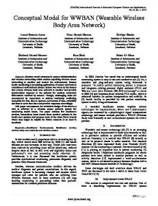
the OFDMA scheme is proposed in this paper. This WiBoC OFDMA has complementary properties to the previous proposal UPHI MT-CDMA [7], in terms of data rate and performance under different channel conditions. Therefore, these two proposals reach the opposite extensions of applications. However, the OFDMA scheme is sensitive to the non-ideal frequency mismatch between a transmitter and a receiver, say carrier frequency offset (CFO) and sampling clock offset (SCO), and a WSN is required and designed in a tiny area in the WBAN applications. This tiny-area requirement leads to the amplified inaccuracy, especially in the generated frequency. As a result, the frequency calibration and pre-calibration are required and explored in this work to maintain the high performance and mega-scale data rate requirements in WBAN applications. This paper is organized as follows. In section II, the system behavior and characteristics are presented, and section III shows the designs of the proposed rotator and synthesizer driven (RSD) frequency pre-calibration. Then the evaluated system performance and designed hardware profile are provided in section IV followed by the conclusion in section V. II. SYSTEM DESCRIPTION A. System Behavior The system behavioral scheme of WiBoC is shown in Fig. 1. Here we depict this operation for multi-user. The body signals are gathered and transmitted from the WSNs. The CPN, which is integrated in a portable device such as a personal digital assistant (PDA), receives the human body signals from WSNs for ubiquitous monitoring. When the WSNs and CPN are activated, they are initially in a reset state. In the beginning of network establishment, the CPN waits for sign-in signals from possible WSNs. After all WSNs join this network, the CPN broadcasts frames to every WSN (downlink process) for timing and frequency synchronizations. After the network synchronization in the downlink process, each WSN starts to gather body signals and transmits to the CPN (uplink process). Finally, the CPN receives the body information from WSNs. The proposed communication system operates in 1.4GHz radio band, and occupies 5MHz bandwidth.
Sign Reset - - - - - - - - in - - - - - - - - - - - - - - - - - - -uplink -------------
WSN 2
Sign - - - - - - - - - - - - - - - - - - - - - - - - - - - - -uplink ----------Reset in
CPN
Broadcast Data ---------------------------------------Reset (downlink) Inspection
Wireless Sensor Node RSD Frequency Pre-Calibration I QPSK F Phase Mapper F Rotator T
Hˆ
C1,l
FEC Bitstream
Time
Frequency Tunable Clock Generator
Fig. 1. System device connections of the proposed WiBoC system Short Preamble
Short Preamble
Synchroniztion Coarse CFO Estimation
GI
GI
Long Preamble
Long Preamble
G SCO I Preamble
Boundary Channel Estimation Detection Fine CFO Estimation
G SCO I Preamble
Long Preamble
Boundary Detection
Long Preamble
Channel Estimation
GI
Signal field
D A C R F
rn
A D C
(a)
SCO Estimation
Central Processing Node
(a) GI
Downlink Synchronizer
WSN 1
GI
Frame Information
Signal field
G I
Data
G I
A D C
R F
Data
Timing Synchronizer FEC Decoder
Payload
Demapper
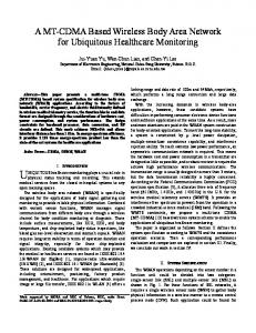
(b) Fig. 2. Frame format (a) downlink frame and (b) uplink frame
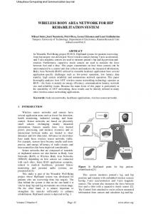
B. Frame Format Fig. 2(a) shows the downlink broadcast frame. The first two repeated short preambles are used for the symbol timing synchronization and the coarse CFO estimation. The following two GIs are for the boundary detection. The subsequent two long preambles are used to perform channel estimation and further fine CFO estimation. In the end of the frame, concatenated SCO preambles are used to perform SCO estimations. Uplink frame structure is shown in Fig. 2(b). The preambles and the data are scrambled into a frame. The first GI is composed of the repeated subset of long preambles. It is used to perform symbol timing synchronization and symbol boundary detection. The following two long preambles are used for channel estimation. The signal field indicates the number of OFDM symbols in this frame. The final part of the frame is the payload data. C. System Block Diagram Fig. 3 shows the system block diagram of a WSN and a CPN. In the WSN, the forward-error-correction (FEC) encoded bitstream is added before the QPSK symbol mapper. The QPSK symbols are then sent into inverse-FFT block and transformed into OFDM symbols. The OFDM symbols are pre-calibrated with the estimated CFO and SCO via the RSD frequency pre-calibration, where the frequency information is from the downlink synchronizer. The downlink synchronizer estimates CFO and SCO from the downlink frame. The phase rotator rotates the data by the estimated CFO value before the data are transmitted. The frequency tunable clock generator [8] generates the accurate clock which is adjusted by the estimated SCO. Therefore, the baseband clock will be tuned accurately by the generator and the SCO effect will be reduced. In the CPN, the received data from the WSN have been pre-calibrated. The synchronizer detects the symbol timing
Frequency Synchronizer
F F T
Phase Recovery
(b) Fig. 3. The WiBoC OFDMA system block diagrams. (a) WSN. (b) CPN.
with symbol correlation results. The synchronized data are then sent into the FFT block. After transformation, the phase recovery is performed to calibrate the data. Then the recovered data are demapped for later FEC decoding. III. THE PROPOSED RSD FREQUENCY PRE-CALIBRATION The CFO and SCO are estimated by the downlink synchronizer and are denoted as H ' and C1,l , respectively [9]. From the estimated value, the RSD frequency pre-calibration is carried out. A. CFO Pre-Calibration Algorithm After the frame detector detects the short preambles via the format in Fig. 2(a), the inner product of the repeated short preambles is used to perform the coarse CFO estimation. This operation is expressed as N �1
z
¦r
n� N
N �1
(rn ) *
n 0
¦r e n
N �1
j 2 SH
(rn ) *
n 0
e j 2SH ¦ | rn |2
(1)
n 0
where N is the length of the preamble, z is the inner product of consecutive two preambles. rn and rn � N are located at the received mth and (m+1)th preambles respectively. The H is the added CFO value, and the estimated CFO is computed via
Hˆ
(1/ 2S ) tan �1 ( z )
(2)
The remaining received data will be compensated by this estimated coarse CFO value. Moreover, the two repeated and coarsely CFO compensated long preambles are used to get fine estimated CFO value following (1) and (2). Suppose H ' is the summation of coarse and fine estimated CFO value. The uplink data pass through the phase rotator in Fig. 3(a) and are rotated �H ' by the multiplication of e � j 2SH ' before transmitting through the uplink channel.
B. SCO Pre-Calibration Algorithm The SCO value is estimated by the long preambles. These preambles after channel equalization and CFO compensation are transformed to frequency domain to perform SCO estimation [9]. The behavior of the clock offset can be modeled as
Cl ,0 � Cl ,1k
(3)
AWGN CFO=100,SCO=100 CFO=100,SCO=100+precal remaining SCO=20 remaining SCO=20+precal design target
-1
10
FER
Tl , k
0
10
-2
10
where k is the index of the subcarrier, and T l , k is the phase -3
rotation of the data at kth carrier in lth preamble. The
10
coefficient Cl ,0 means the CFO value. The slope Cl ,1 is used to estimate SCO. For SCO estimation and compensation, only the value Cl ,1
-4
10
is considered here. The indices of the pilots used to estimate SCO in each long preamble are [ k1 , k2 ,� , km ]. The SCO effect on these pilots can be described as the following matrix form
2
3
4
5
6
7 SNR [dB]
8
9
k1 º » k2 » : », Cl » : » k m »¼
ªCl ,0 º « » , and Tl ¬Cl ,1 ¼
(4) ªTl , k1 º « » «Tl , k2 » «: » « » «: » « » «¬Tl , km »¼
CFO SCO design target
least square algorithm.
( K T K ) �1 K T Tl
80
60
40
20
0
We can obtain the Cl ,1 in the preamble phase rotation by
Cl
12
120
remaining CFO & SCO value [ppm]
where K
ª1 « «1 «: « «: «1 ¬
Tl
11
Fig. 4. System performance with CFO and SCO effects
100
KCl
10
(5)
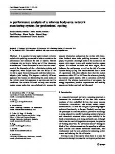
Then the SCO value is estimated. In order to increase the estimation accuracy, we use several preambles to estimate and obtain an average value. According to the estimated value in (5), the frequency tunable clock generator is able to alter its generated frequency to reduce the sampling rate mismatch from the CPN side. IV. SIMULATION RESULTS The proposed RSD frequency pre-calibration is evaluated in the WiBoC OFDMA system under AWGN channel conditions. The FEC encoder (convolutional code) is designed with coding rate R=1/2, K=7, and generator polynomials g0=1338 and g1=1718. Each uplink frame is composed of 8192 information bits, and the system performance in each channel condition is simulated with 5000 uplink frames. To elaborate the CFO and SCO pre-calibration efforts, the system performance is illustrated in Fig. 4. The performance target is frame error rate (FER) 1%. Without the proposed RSD pre-calibration, the system performance cannot converge under large CFO and SCO conditions, i.e. 100ppm. When the SCO=20ppm exists in the transmission link, the resulting SNR at FER=1% without
-20
0
20
40
60
80 100 120 140 added CFO & SCO [ppm]
160
180
200
Fig. 5. The remaining CFO and SCO after pre-calibration
pre-calibration is 5.5 dB, which is about 0.6dB SNR loss compared to the pure AWGN condition. When the RSD pre-calibration is applied with this same SCO amount, the resulting SNR loss remains unchanged. Moreover, it is also found when the SCO value is enlarged up to 100ppm with the same RSD approach, the reached SNR is the same, i.e. about 5.5dB. In other words, we are able to obtain the same system performance with any amount of SCO more than 20ppm by the RSD frequency pre-calibration. The performance compared to the ideal curve has only about 0.6dB SNR loss. The summary of the system tolerance is shown in the TABLE I. Figure 5 shows the performance of system compensation and pre-calibration. Our design target of the calibrated remaining SCO is within 20ppm. For CFO, the pre-calibration algorithm compensates the CFO and eliminates it to about 0ppm when the CFO effect is below 100ppm. For SCO, the pre-calibration reduces this effects with remaining SCO less than 20ppm under the SNR=6dB condition. The system tolerates the channel effects of CFO below 100ppm with CFO pre-calibration. Comparing to the system without SCO pre-calibration, the one with SCO pre-calibration tolerates larger range of SCO up to 100ppm, resulting in SNR = 5.5 dB at FER = 1%.
TABLE I SYSTEM PERFORMANCE SUMMARY CFO+SCO+AWGN Channel Condition AWGN without pre-cal with pre-cal CFO (ppm) 0 0 100 SCO (ppm) 0 20 100 SNR (dB) at FER=1% 4.9 dB 5.5 dB 5.5 dB
TABLE III WIBOC OFDMA SYSTEM SPECIFICATION
TABLE II SYSTEM COMPARISON IN THE ALLOWABLE FREQUENCY ERRORS System
CFO Tolerance
SCO Tolerance
Low-Precision Ref. Frequency Allowed
Bluetooth [1] Zigbee [2] MIThril [3] CodeBlue [4] Human++ [5]
±20ppm ±40ppm ±30ppm ±25ppm N/A
±20ppm ±40ppm ±30ppm ±25ppm N/A
No No No No No
Proposed WiBoC
±100ppm
±100ppm
Yes
V. CONCLUSION A rotator and synthesizer driven frequency pre-calibration is designed in this paper. With this proposal, the communications system is enabled with larger frequency errors. All the parameter estimation and signal compensation are achieved via all-digital signal processing and circuit designs. With the allowable low-precision reference clock, this makes a less-cost and smaller-area chip design possible in the tiny-area oriented applications. As a result, this proposed RSD pre-calibration enables a robust and low cost design for WBAN applications. *
Uplink transmitter is defined as the WSN excluding the downlink synchronizer.
Feature
Technology
Std. 90nm CMOS
RSD Pre-calibration area
50451 Pm2
RSD Pre-calibration power
77.5 PW
RF band
1395-1400MHz
Spectrum Bandwidth
5MHz
Constellation Mapper
QPSK
IFFT/FFT Block Size
64
Maximum Data Throughput
4.85 Mbps
Guard Interval Duration
0.4Ps
Data Bit per OFDM symbols
48 K=7 Convolutional Code with Generator Polynomial (133,171)
FEC Encoder
CFO: carrier frequency offset SCO: sampling clock offset
TABLE II summarizes the tolerated frequency offset in terms of CFO and SCO in the possible WBAN proposals. From those systems [1-5], the maximum frequency-error tolerance is defined no more than ±40ppm. This value makes it difficult to utilize a low-precision reference clock for the overall design area and cost shrinking. In other words, the proposed WiBoC enables a ±100ppm-CFO and a ±100ppm-SCO tolerance, and eases the design efforts in the reference clock, presenting a low cost design for WBAN applications. In Fig. 6, we illustrate a full WSN baseband layout view with the proposed WiBoC downlink synchronizer, uplink transmitter*, and phase-frequency tunable clock generator (PFTCG). The PFTCG includes and performs the frequency-tunable clock generator behavior. The designs of the SCO estimation (a), CFO estimation (b), and CFO pre-calibration (c) are also sketched. The overall design characteristics are summarized in TABLE III in terms of hardware and system specifications. The designed hardware is evaluated in UMC 90nm process. In the data pre-calibration, the overall power consumption is 77.5 PW with 70.4PW for the parameter estimation. In the system design features, the WiBoC follows the constraints defined in WMTS with the provided maximum data rate 4.85Mbps.
Parameter
Uplink
b
Transmitter*
c
b a
PFTCG
a
Downlink Synchronizer
Fig. 6. WSN design layout view
REFERENCES [1]
[2]
[3] [4]
[5]
[6]
[7]
[8]
[9]
Wireless Medium Access Control (MAC) and Physical Layer (PHY) Specifications for Wireless Personal Area Networks (WPANs), IEEE Standard 802.15.1, 2005. Wireless Medium Access Control (MAC) and Physical Layer (PHY) Specifications for Low-Rate Wireless Personal Area Networks (LR-WPANs), IEEE Standard 802.15.4, 2003 S. Pentland, “Healthwear: Medical Technology Becomes Wearable,” IEEE Computer Society, pp. 42-49, May 2004. K. Lorincz, D.J. Malan, Fulford-Jones, Thaddeus R.F., A. Nawoj, A. Clavel, V. Shnayder, G. Mainland, S. Moulton, and M. Welsh, “Sensor Networks for Emergency Response: Challenges and Opportunities, ” IEEE Pervasive Computing, pp.16-23, Oct. 2004. B. Gyselinckx, C. Van Hoof, J. Ryckaert, R.F.Yazicioglu, P. Fiorini, V. Leonov, “Human++: autonomous wireless sensors for body area networks, ” Proceedings of the IEEE Custom Integrated Circuits Conference, pp.13-19, Sept. 2005 Federal Communications Commission, “Amendment of Parts 2 and 95 of the Commission’s Rules to Create a Wireless Medical Telemetry Service,” FCC Washington, D.C., Rep. FCC00-211, 2000. Jui-Yuan Yu, Ching-Che Chung, Wan-Chun Liao, and Chen-Yi Lee, “A sub-mW Multi-Tone CDMA Baseband Transceiver Chipset for Wireless Body Area Network Applications,” IEEE International Solid-State Circuits Conference Digest of Technical Papers, pp.364-609, Feb. 2007. Jui-Yuan Yu, et. Al, “An All-Digital Phase-Frequency Tunable Clock Generator for Wireless OFDM Communications,” in Proc. 2007 IEEE Int. Conf. SoC, pp. 305-308, Sep. 2007. Hung-Kuo Wei, “A Frequency Estimation and Compensation Methods for High Speed OFDM-based WLAN Systems,” M. S. thesis, Dept. Electron. Eng., NCTU, Hsinchu, Taiwan, 2003.