Capacitive sensors are particularly sensitive to parasitic ca- pacitance at the ...
Architecture of a common lock-in sensing scheme for capacitive sensing. Fig. 2.
244
IEEE JOURNAL OF SOLID-STATE CIRCUITS, VOL. 38, NO. 2, FEBRUARY 2003
An Offset-Canceling Low-Noise Lock-In Architecture for Capacitive Sensing Maziar Tavakoli, Student Member, IEEE, and Rahul Sarpeshkar, Member, IEEE
Abstract—We describe an offset-canceling low-noise lock-in architecture for capacitive sensing. We take advantage of the properties of modulation and demodulation to separate the signal from the dc offset and use nonlinear multiplicative feedback to cancel the offset. The feedback also attenuates out-of-band noise and further enhances the power of a lock-in technique. Experimentally, in a 1.5- m BiCMOS chip, a fabrication dc offset of 2 mV and an intentional offset of 100 mV were attenuated to 9 V. Our offsetcanceling technique could also be useful for practical multipliers that need tolerance to fabrication errors. We present a detailed theoretical noise analysis of our architecture that is confirmed by experiment. As an example application, we demonstrate the use of our architecture in a simple capacitive surface-microelectromechanical-system vibration sensor where the performance is limited by mechanical Brownian noise. However, we show that our electronics limits us to 30 g Hz, which is at least six times lower than the noise floor of commercial state-of-the-art surface-micromachined inertial sensors. Our architecture could, thus, be useful in high-performance inertial sensors with low mechanical noise. In a 1–100-Hz bandwidth, our electronic detection threshold corresponds to a one-part-per-eight-million change in capacitance. Index Terms—Accelerometer, analog multiplier, capacitive sensing, lock-in technique, low noise, MEMS sensor, mixer, multiplicative feedback, nonlinear feedback, offset cancellation.
I. INTRODUCTION
I
N THE past decade, tremendous progress has been achieved in miniaturizing and improving the performance of sensors. The sensor’s overall performance is often limited by its electronics, which must amplify and condition extremely small outputs from its sensing elements [1]. Improvements in the electronic interface are in many cases crucial to optimizing overall sensor performance. Lock-in sensing schemes are commonly used in signal-detection applications to lower errors due to low-frequency phenomena. For example, in applications such as capacitive inertial sensing, lock-in techniques are important for detecting tiny signals that would otherwise be swamped by high levels of noise. Several commercial accelerometers and sensitive instrumentation systems employ lock-in techniques to detect faint signals [2]. Manuscript received January 8, 2002; revised November 7, 2002. This work was supported by the Defense Advanced Research Projects Agency through the Office of Naval Research under Grant N00014-99-1-0438 to the California Institute of Technology and under Subcontract 1007021 to the Massachusetts Institute of Technology. The authors are with the Department of Electrical Engineering and Computer Science, Massachusetts Institute of Technology, Cambridge, MA 02139 USA (e-mail:
[email protected];
[email protected]). Digital Object Identifier 10.1109/JSSC.2002.807173
Analog multipliers are an essential building block of lock-in systems because they perform the demodulation necessary to extract the input signal. One of the most critical impairments of an analog multiplier is its dc offset. Such offset can decrease the multiplier’s gain, degrade its noise performance and minimum detectable signal, and increase the nonlinearity and distortion introduced by the multiplier in the modulation or demodulation process. Some strategies to compensate for the dc offset of mixers have been proposed in the literature; for example, see [3]. Most of these approaches are digital and necessitate analog-to-digital conversion when the mixing operation is performed on analog signals. This extra conversion process often adds to the power consumption and complexity of the system. In this paper, we introduce a simple, efficient, and purely analog technique to automatically nullify the dc offset in an analog multiplier. In particular, we use the properties of modulation and demodulation to separate signal from offset and we use nonlinear multiplicative feedback to cancel the offset. The automatic offset cancellation ensures that the multiplier is tolerant to fabrication errors. Capacitive sensors are particularly sensitive to parasitic capacitance at the input of the electronic interface [4]. In our first stage of signal conditioning, we describe a custom low-noise band-pass amplifier and a standard inverting-feedback topology to achieve parasitic insensitivity. We perform careful theoretical analyses of all noise sources in our architecture and use the results of these analyses to achieve a good low-noise experimental design. In an example use of this architecture in a microelectromechanical system (MEMS) vibration sensor, we also employ lowfrequency electrostatic force feedback [5] to cancel mismatch between the sensing capacitances. Our architecture’s low electrical noise floor could be useful in a six-fold improvement in the performance of state-of-the-art commercial surface-MEMS sensors if their mechanical Brownian noise is lowered. The outline of this paper is as follows. In Section II, we review lock-in architectures for capacitive sensing. In Section III, we present our idea for multiplier offset cancellation, analyze it, and present experimental data. (An abbreviated description of this idea has also been reported in [6].) In Section IV, we present our lock-in architecture and an analysis of its noise performance. In Section V, we explain how we combine our electronic architecture with a MEMS structure to implement a vibration sensor; we also present experimental results and discuss the factors limiting our sensor’s performance. In Section VI, we conclude by summarizing our contributions.
0018-9200/03$17.00 © 2003 IEEE
TAVAKOLI AND SARPESHKAR: OFFSET-CANCELING LOW-NOISE LOCK-IN ARCHITECTURE FOR CAPACITIVE SENSING
245
dc offsets in the system are large enough to saturate the multiplier output or to drive it into a nonlinear regime of operation, then the final output will suffer considerable distortion and the benefits of lock-in techniques will start to fade. In Section III, we discuss a nonlinear feedback technique that ensures that the analog multiplier always operates in a nearly ideal regime. The feedback is also effective in attenuating out-of-band noise and, hence, further enhances the power of a lock-in technique. III. OFFSET COMPENSATION IN ANALOG MULTIPLIERS
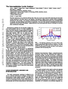
Fig. 1. Architecture of a common lock-in sensing scheme for capacitive sensing.
Fig. 2.
Analog multipliers are usually balanced circuits and the presence of dc offset degrades their performance considerably. This offset can be caused by different factors. For example, the two inputs to the multiplier may have dc offsets generated by preceding blocks, or more frequently, device mismatches in the multiplier can generate offset. The use of ac coupling prior to the multiplier block does not remove offset inherent in the multiplier itself. Our technique is capable of attenuating all offset. Although the technique described in this paper will be applicable to all forms of analog multipliers regardless of their circuit topology, we will focus our attention on a Gilbert multiplier cell. This multiplier is the basis for most integrated-circuit balanced multiplier systems, has been widely analyzed in the literature, and was the one we used.
Frequency domain representation of the lock-in technique.
A. Effects of DC Offset on Analog Multipliers II. REVIEW OF LOCK-IN CAPACITIVE SENSING Lock-in techniques are used to sense very small electrical signals. In a capacitive surface-MEMS inertial sensor, for example, lock-in techniques enable sensing of subangstrom displacements of the inertial proof mass via microvolt or submicrovolt signal detection. Lock-in techniques attenuate low-frequency error sources such as the input-referred noise and offset of the sensing electronics, substrate coupling, and electromagnetic interference (EMI). Figs. 1 and 2 demonstrate a common lock-in sensing scheme used for capacitive inertial sensing. Fig. 1 shows a schematic representation while Fig. 2 shows spectral representations of various lock-in signals. Two antiphasic high-frequency carrier and in Fig. 1) are connected to the stationary signals ( and ). Their plate of each of two sensing capacitors ( common movable plate is attached to a proof mass. An imbalance in the sensing capacitors, caused by the motion of the proof-mass plate modulates the carrier signal to create a modulated signal [5]. The modulation recenters the input baseband spectrum of the plate motion at the carrier frequency. The specis then separated from the low-frequency error spectrum of trum as shown in Fig. 2. Then, an analog multiplier (or mixer) by a replica of the high-frequency carrier signal to multiplies generate . The latter demodulation process interchanges the and location of input signal spectrum and error spectrum in is low-pass filalso performs some amplification. Finally, . The low-pass filtering preserves the detered to generate , while the low-frequency errors are greatly sired signal in suppressed. Lock-in techniques are useful if and only if the analog multiplier is functioning within its linear range of operation. If the
The differential output voltage of a Gilbert multiplier is given by [7]
(1) and are the input signals and is the thermal where voltage. The dc offset can make the inputs significant with , such that the approximation is respect to no longer valid. The effective gain of the multiplier is then decreased and, consequently, there is a reduction in its sensitivity. Furthermore, offset also increases the nonlinearity of the output signal by causing an asymmetric response for positive and negative inputs. In addition to a decrease in gain, offset deteriorates the noise behavior of the multipliers, which have their lowest input-referred noise when they are balanced. The presence of offset in the multiplier’s output is also destructive to subsequent blocks, especially if these blocks are implemented as balanced topologies. For all the above reasons, it is important to develop a mechanism to compensate for and cancel the offset of a multiplier. We show how we can take advantage of the properties of modulation, demodulation, and negative feedback to accomplish this goal. Although a predistortion technique [7] can provide increased linearity in a multiplier and provide some robustness to offset, it worsens the noise performance of the multiplier block unless there is considerably more power spent in the emitterconverters, which are necessary in this degenerated technique. To get improved linearity that ensures robustness to
246
IEEE JOURNAL OF SOLID-STATE CIRCUITS, VOL. 38, NO. 2, FEBRUARY 2003
dc offset (and other very-low-frequency information), and applies this signal back to the original multiplier. Intuitively, because we have two multiplication operations by our “Ref” input in the loop, its sign does not matter anymore and the feedback loop remains negative at all times. The loop forces the feedback signal to adapt slowly to eliminate the net dc offset of the multiplier. The reason that we use a nonlow-pass-filtered version of the multiplier’s output as an input to the feedback multiplier instead of the filtered version requires more attention. Let us assume that Ref Input Signal Input Fig. 3. Configuration of the nonlinear offset-compensated multiplier.
offset, . To keep the input-referred noise of the is large. A multiplier low, must be small, implying that large dc bias current is then necessary to provide the increased . Our technique does not incur this power cost for reduced noise. Furthermore, the offset in a multiplier that only uses predistortion remains uncompensated. Our technique removes offset and, consequently, improves linearity. B. Nonlinear Offset-Compensating Technique A linear feedback loop in our system could be formed by placing an amplifier to monitor the multiplier outputs, extract their dc offset as an error, and adjust one of the inputs of the multiplier to nullify that offset. However, because this system contains a nonlinear element (i.e., the multiplier), linear feedback is not useful. The gain of the nonlinear multiplier depends on both of its inputs [see (1)]. Therefore, given a linear negative-feedback loop, when the sign of the second input is inverted, the negative-feedback loop becomes a positive-feedback loop and instability invariably results. The solution to this problem is to employ a nonlinear block in the feedback path. We need an amplifier in which the sign adjusts itself according to the sign of multiplying inputs of the original amplifier such that the loop always maintains a negative loop transmission. In fact, further analysis reveals that a second multiplication process is required in this compensation technique and, therefore, we replace the feedback amplifier with a second offset-compensating multiplier. Fig. 3 shows the configuration of this nonlinear offset-compensating technique. The two multiplying inputs of the original multiplier are designated “Signal” and “Reference” (“Ref”) inputs. When the multiplier is used in the lock-in architecture of signal of Fig. 1, Fig. 1, the “Signal” input in Fig. 3 is the while the “Ref” input in Fig. 3 is the multiplying replica of the carrier signal of Fig. 1. In Fig. 3, the feedback multiplier is labeled “Offset Compensator.” We observe that the “Signal” and “Ref” inputs are mixed by the multiplier. The lock-in scheme of Fig. 1 suggests that the multiplier’s output should then be low-pass filtered to obtain the baseband signal of interest and to eliminate errors and noise. In parallel, the offset compensator senses the output, multiplies it by the “Ref” input to adjust the sign of its gain, low-pass filters the result to extract the output’s
In general, the “Ref” input is a well-defined signal with known characteristics, usually under the control of the system’s user. On the other hand, the “Signal” input usually has properties that are less controllable. For example, the “Ref” and the “Signal” inputs, respectively, represent the carrier signal and the capacitive interface output in the inertial sensor and they represent a local-oscillator signal (LO) and an antenna-dependent radio-frequency signal (RF) in a coherent radio receiver. In Fig. 3, the output of the multiplier is Ref Input
Signal Input
(2) The terms of interest to us are underlined. These terms carry the modulated offset information. They are demodulated by the offset compensator and then low-pass filtered to result in and a signal that contains the offset information of both . This signal is, therefore, used as our feedback signal. If, instead, we had used the low-pass-filtered output in our feedback loop in Fig. 3, we would have lost these two terms. term Instead, we would have had to rely on the in (2) to extract the offset information. However, when one of the offsets is zero, the latter product term is zero and no feedback adaptation takes place. In this case, the output does not possess any dc content due to offset because one of the multiplying inputs is offset free. However, the circuit is not balanced because the other multiplying input still has an offset. Therefore, our feedback mechanism utilizes the summation and terms to balance the circuit and works of the even if one of the offsets is zero. Fig. 4 shows a simplified circuit schematic of our nonlinear offset-compensated multiplier. The core of the multiplier’s block is based on the Gilbert multiplier cell with two different and ) conversions of the output. One output pair ( nects to the input of the offset compensator in order to initiate the feedback pathway, while the other pair is a low-pass-filtered and and forms the ultimate version of these outputs at set the output of the multiplier. The off-chip capacitors
TAVAKOLI AND SARPESHKAR: OFFSET-CANCELING LOW-NOISE LOCK-IN ARCHITECTURE FOR CAPACITIVE SENSING
Fig. 4.
247
Circuit schematic of the nonlinear offset-compensated multiplier.
Fig. 6. Experimental output waveforms of the multiplier. (a) Without offset compensation. (b) With offset compensation. Fig. 5. Block diagram of the offset-compensated multiplier.
bandwidth of the circuit. The offset-compensator block is basically a folded MOS-bipolar version of the Gilbert cell with cascode current mirrors utilized to increase its gain. Its input stage consists of pMOS transistors to reduce flicker noise, which is the dominant noise source of this block. The output of the offset compensator is low-pass filtered by a large and connects to the “In_” node to close off-chip capacitor the feedback loop. Fig. 5 illustrates the linearized block diagram of the offsetcompensated multiplier. The algebra shows that the circuit’s offset, referred back to the input, is given by Input-referred Offset
(3)
represents the gain of the original multiplier, while represents the gain of the offset-compensating multiplier. The in the ciroffset-compensating multiplier adds a new offset . cuit although it was supposed to reduce the original offset is added at the output of the original multiplier However, after its gain is in effect. Consequently, the block diagram of is attenuated by Fig. 5 and (3) show that the effect of when referred back to original multiplier’s input. Since is is small. Meanwhile, 43 V/V in our circuit, the effect of is 2100 V/V in our design.
C. Experimental Results The offset-compensated multiplier, as part of the whole electronic sensing architecture presented in this paper, was fabricated in a 1.5- m BiCMOS n-well process. The fabricated offset-compensated multiplier was tested experimentally; Fig. 6(a) and (b) illustrates the output waveforms of the circuit and from Fig. 3). The multiplying inputs in (i.e., Fig. 6(a) and (b) have a small difference in their frequency, which creates a modulation signal similar to those seen in a capacitive inertial sensor. Specifically, their frequencies differ by 50 Hz around a base carrier frequency of 500 kHz. In the above experiment, we intentionally introduced offset in the multiplier to help with visualizing the efficiency of our compensating technique. In Fig. 6(b), the offset-compensating mechanism is active. In Fig. 6(a), this mechanism is deactivated by grounding the feedback signal (i.e., “In_” node from Fig. 4). In the uncompensated case, we see that the output waveforms have a large dc offset and are nonlinear. Neither of these properties is observed in the compensated waveforms of Fig. 6(b). Moreover, signal amplitudes and, thus, the gain are larger by a factor of approximately two when the offset compensation is in effect, compared to when it is not. Fig. 7(a) shows the measured dc transfer curves of our multiplier when the compensating loop is inactive. It has the typical characteristics of an ordinary multiplier. In Fig. 7(b), the
248
IEEE JOURNAL OF SOLID-STATE CIRCUITS, VOL. 38, NO. 2, FEBRUARY 2003
Fig. 8. Topological configuration of the entire electronic capacitive sensing architecture.
IV. LOW-NOISE ELECTRONIC ARCHITECTURE One of the major drawbacks of a capacitive inertial sensor with a configuration like the one in Fig. 1 is the signal attenuation due to parasitics at the sense node ( in Fig. 1). Since the sensing capacitors are small and comparable to typical parasitic capacitances on chip, the existence of such parasitics results in significant attenuation of the signal level and makes the gain of the sensor dependent on poorly controlled parameters. Specifireduces the sensor’s output by cally, a parasitic capacitance , where 2 is the total sensing a factor equal to capacitance. Fig. 7. Measured dc transfer characteristics of the multiplier. (a) Without offset compensation. (b) With offset compensation.
same curve is plotted for a multiplier with offset compensation. In this case, the dc value of the output remains at nearly zero even in the presence of considerable dc offsets at both inputs (i.e., “Signal” and “Ref” inputs in Fig. 3), which means that our offset cancellation is effective. In another experiment, we measured the input-referred offset of the multiplier to be 9 V with offset compensation and 1–2 mV without. An intentional offset of 100 mV was also attenuated to 9 V. Hence, we achieved an offset reduction of almost four orders of magnitude in our multiplier. The designed mechanism, which has been shown to attenuate dc offset, also attenuates low-frequency noise in the multiplier block within the closed-loop bandwidth of the offset-compensating feedback loop. In other words, our automatic offset-compensating mechanism reduces the flicker noise in the multiplier as well. In general, if the closed-loop bandwidth of the offset-compensating loop is large enough to encompass all frequencies outside the lock-in band of interest, we can use it to attenuate the effects of noise in all these out-of-band frequencies. Thus, the power of a lock-in technique in suppressing these out-of-band frequencies is further enhanced. The bandwidth of the offset-compensating loop is made as large as necessary to remove unwanted noise, but not so large that it interferes with the lock-in band.
A. Front-End Band-Pass Amplifier In our first stage of signal conditioning, to ensure a gain that is invariant with parasitics, we insert an inverting-gain amplifier between the capacitive-interface output (which we call the sense node) and the subsequent electronic interface (demodulator). Furthermore, the operational amplifier used in the circuit is a band-pass amplifier with its passband centered at the lock-in carrier frequency. Fig. 8 shows the entire topological configuration of our architecture. The inverting configuration with high loop gain ensures that the closed-loop gain of the system is independent of parasitics and dependent only on the sensing and feedback capacitances. However, the presence of parasitics does degrade the noise performance of the closed-loop amplifier. The band-pass amplifier provides some rejection to unwanted signal components not near the lock-in band. Fig. 9(a) shows the circuit schematic of this band-pass amplifier. The primary input stage of the amplifier consists of tranand along with a resistive load . The resistive sistors load is used instead of a transistor active load because, with the same bias current, a resistive load generates less noise referred to amplifier’s input than an active load. However, due to area constraints, the gain of such a resistively loaded input stage is not sufficiently high (typically, around 5 V/V) to create an amplifier with significant open-loop gain. Thus, we employ a second gain stage, which in Fig. 9(a) consists of – . implements low-pass filtering at the amplifier’s output and determines the amplifier’s upper frequency of operation. The amand source-folplifier’s output is also buffered by the lower transistors, low-pass filtered (due to ) and fed back to
TAVAKOLI AND SARPESHKAR: OFFSET-CANCELING LOW-NOISE LOCK-IN ARCHITECTURE FOR CAPACITIVE SENSING
Fig. 10.
249
Block diagram of the front-end band-pass amplifier.
Fig. 11. Simplified representation of the electronic sensing architecture, used for noise analysis.
and represent the time constants of the forward-path and feedback-path low-pass filters, respectively. B. Electrical Noise Analysis
Fig. 9. (a) Circuit schematic and (b) frequency response of the front-end band-pass amplifier.
the negative terminal of a secondary input stage ( and ) to close a negative-feedback loop. The latter loop implements the high-pass functionality of the band-pass amplifier via a low-pass and form block in this feedback path. The transistors a source-follower output buffer to buffer the output of the am– proplifier and perform level shifting. The transistors vide the required bias currents. The frequency response of this band-pass amplifier is displayed in Fig. 9(b). While its passband is designed to be wide enough to give our system the flexibility to operate with any lock-in carrier frequency ranging from 100 kHz–1 MHz, we used a 500-kHz carrier frequency in our experiments. Fig. 10 illustrates the block diagram of the band-pass amplifier. The various noise sources of the amplifier are also shown. These noise sources are important in the overall noise , , and performance of the architecture. In Fig. 10, denote the gains of primary input stage, secondary input stage, and the gain stage, respectively. The parameters
Fig. 11, which is a simple representation of the electronic architecture of Fig. 8, highlights useful parameters for noise analis the parasitic capacitance between the sense ysis. In Fig. 11, sets the node and the substrate (or ground). The resistor potential at the sense node to a value close to the ground pois poorly detential. Without this resistor, the dc value of must be chosen such that the dc curfined. The value of rent through this resistor is much smaller than the signal current through sensing capacitors. This translates into the condition [1] M for
kHz and
fF
(4)
Since such large resistors consume a lot of silicon area, we current–voltage ( – ) use a nonlinear element with a . The element consists of characteristic to implement a pMOS transistor with its body terminal connected to its source and its gate terminal connected to drain [8]. It functions like two back-to-back diodes, with a subthreshold MOS and the exponential diode implementing one half of the parasitic bipolar in the MOS transistor implementing the other . Under the small-signal ac operation of our half of the lock-in sensing scheme, this adaptive element exhibits at least of resistance; therefore, for all practical purposes, 10 –10 can be assumed to be absent. Based on Fig. 11, the block diagram of Fig. 12 is developed. represents the equivalent input-referred noise In Fig. 12, represents the of the band-pass amplifier of Fig. 11,
250
IEEE JOURNAL OF SOLID-STATE CIRCUITS, VOL. 38, NO. 2, FEBRUARY 2003
the sensing and the parasitic capacitors. Equations (6) and (7) then lead to a relationship for the electrical noise at the sense node ( ) V Hz
Fig. 12. Block diagram of the electronic sensing architecture, used for noise analysis.
input-referred noise of the offset-compensated multiplier, represents the total capacitance at the sense node and is given , represents the by , and is net differential capacitance change, the amplitude of the high-frequency carrier. To quantify the effects of electrical noise, it is useful to refer the noise of all blocks in Fig. 8 to their inputs. It is also useful to evaluate the electrical noise at two different points in our architecture: The first such point is the output of the band-pass amplifier and the second point is the sense node where the capacitive sensor output is interfaced to the input of the band-pass amplifier. Electrical noise at the output of the band-pass filter can easily be converted to an equivalent input-referred acceleration noise by dividing by the transfer function between the acceleration and the voltage at this output . For frequencies input below the mechanical resonant frequency , this transfer function is given by [4] to be V/g
(5)
is the interplate sensing capacitor distance, m/s is the acceleration due to gravity, is the resonant frequency of the moving proof mass, and the accelis expressed in units of . This transfer function eration is well controlled and predicted by electrical and mechanical parameters. Electrical noise at the output of the band-pass filter may be referred back to the sense node by dividing by the transfer function and band-pass amplifier output between the sense node . The block diagram of Fig. 12 helps us evaluate this gain to be where
V/V
(6)
, we assume that the In deriving (6), besides ignoring loop gain of the feedback configuration in Fig. 12 is much larger than one. Since the passband open-loop gain of the band-pass amplifier is large, this assumption is a very good one. From the block diagram of Fig. 12, after some simple algebra, we evaluate the electrical noise at the band-pass amplifier output ) to be ( V Hz
(7)
Note that the voltage fluctuations at the band-pass amplifier input cause charge to flow onto the feedback capacitor from both
(8)
, which is the input-referred noise We now calculate power of the band-pass amplifier block and then substitute for it in (7) and (8). Careful analysis of the band-pass amplifier’s block diagram in Fig. 10 followed by some algebra yields a band-pass amplifier input-referred noise of V Hz (9) In (9), we ignored the noise of the amplifier’s output buffers and ). The contribution of these noise sources, ( when referred back to the input, are divided by the open-loop band-pass amplifier’s gain (greater than 50 dB) and may be neglected. , , and represent the input-referred The symbols noise of primary input stage, secondary input stage, and the gain stage of the band-pass amplifier, respectively. We evaluate these noise sources through the following procedure. The small-signal circuit including the noise generators for each device in the band-pass amplifier’s circuit is found; then, the transfer funcfrom each noise generator to the output is tion calculated while zeroing all other noise generators; then, the ; total output noise is obtained to be finally, the input-referred noise is evaluated to be , where is the transconductance of the primary input stage. We then obtain the following results: V Hz
(10)
V Hz
(11) V Hz
(12)
The lock-in technique eliminates the effects of flicker noise in the band-pass amplifier and, thus, flicker noise was ignored in deriving (10)–(12). , the input-referred noise Similarly, we may calculate power of the offset-compensated multiplier. However, as observed in Fig. 12, this noise enters the circuit after the band-pass amplifier stage and gets divided by the square of the band-pass V/V ), when referred amplifier’s gain (typically, around back to the sense node [see (8)]. Thus, its effective noise contribution to the architecture is greatly reduced. -like Finally, we discuss the noise due to nonlinear . From Fig. 11, we calculate that the noise element is equal to power that appears at the sense node due to . Equation (4), along with the fact is extremely small, reveals that this noise, at its worst that case, is at least one order of magnitude smaller than the total electrical noise at the sense node due to other noise sources. Therefore, it contributes insignificant noise to the architecture.
TAVAKOLI AND SARPESHKAR: OFFSET-CANCELING LOW-NOISE LOCK-IN ARCHITECTURE FOR CAPACITIVE SENSING
Fig. 14.
Fig. 13. Experimental input electrical noise of the electronic sensing architecture. Unlike the low-frequency noise of the multiplier block, the 1=f noise of the offset compensator block is not subject to lock-in filtering, although it is attenuated by our offset-compensation scheme. While this flicker noise is minimized by using large pMOS transistors at the input of the offset compensator block, some residual 1=f noise is still observed in Fig. 13.
1) Theoretical Electrical Noise Calculations: To obtain a theoretical estimate for the total electrical noise, we use the folfF, fF, m, lowing design values: V, and kHz. Further, we measure (the mechanical resonant frequency) to be 20 kHz and calculate to be about 680 fF. This value includes the bond-pad parasitics, the input capacitance of the electronic interface, and the mechanical structure parasitics. From (5)–(12), the total calculated broad-band electrical noise at the output of the band-pass amplifier is 278 nV Hz. This noise is equivalent to 13.5 nV Hz of electrical noise at the circuit’s sense node. In our circuit, we have a simple first-order low-pass filter with a corner frequency of 100 Hz at the final demodulator output. Thus, the total root mean square (rms) electrical noise over this bandwidth computes to at the sense node. 170 nV 2) Experimental Electrical Noise Results: The entire electronic sensing architecture was fabricated in a 1.5- m BiCMOS MOSIS n-well process and occupies an area of about 670 m by 550 m. The operational power-supply range is 5–12 V. We obtained noise measurements on our battery-powered circuit with a SR785 Spectrum Analyzer. The total power consumption was 20 mW. Fig. 13 shows the noise spectrum of our sensing architecture at its sense node. A low-pass characteristic with an expected cutoff frequency of approximately 100 Hz is evident in the Fig. 1. Integrating the noise plot of Fig. 13 over the whole of electrical noise at the frequency band results in 200 nV sense node. This figure corresponds to a 100-Hz bandwidth with a first-order rolloff filter and yields an effective electrical noise of 16 nV Hz per unit bandwidth. This means that the error between our calculated and measured electrical noise is less than 1.5 dB. In another experiment, we measured the electrical noise of our sensing architecture at the output of the band-pass amplifier. Using the well-defined relationship between this output and the acceleration input expressed in (5), we compute the equivalent
251
Vibration sensor test setup.
input acceleration noise floor to be 30 g Hz, assuming that all the noise in the system is only electrical. We confirmed the acceleration-to-band-pass-amplifier-output gain using a piezoelectric actuator, the known millivolt-per-gravity-acceleration sensitivity of a calibration accelerometer (ADXL105) and experimentally determined resonant frequencies of the calibration accelerometer and of our vibration sensor. Further details of our experimental setup are discussed in Section V. V. EXAMPLE APPLICATION IN A MEMS VIBRATION SENSOR The fabricated electronic sensing architecture was packaged, as an example application, with a single-axis MEMS accelerometer to create a vibration sensor. This accelerometer was fabricated in the Cronos surface-micromachined process with two available layers of structural polysilicon. The sensor has 2- m -thick mechanical structures that comprise a proof mass, stationary comb fingers, and anchors to the substrate. The sensor region measures 1.3 mm by 0.6 mm. Fig. 14 shows a photograph of the test setup utilized to evaluate the performance of our MEMS vibration sensor. The sensor consists of a MEMS die, with mechanical sense elements and an electronic die, with our electronic sensing architecture. The two dice are wire bonded in a common chip package and the package is mounted on a rigid board. A state-of-the-art surface MEMS precision accelerometer (Analog Devices’ ADXL105) is also mounted on the same rigid board adjacent to the test package. The whole board is shaken by a piezoelectric actuator (NEC Corporation’s AE0505D16, sold by Thorlabs Inc.). A. Mechanical Noise Analysis In addition to electrical noise, mechanical damping causes noise in the vibration sensor. Since the proof mass has a mass on the order of one microgram, viscous damping of the proof mass by air molecules is a significant source of energy dissipation creating thermal Brownian noise [9]. Brownian noise may be represented as a white-noise force generator with power spectral density [9] N Hz
(13)
is the viscous damping coefficient. Mechanical where damping arises from both gas damping and structural losses; however, structural losses are much lower than viscous effects
252
IEEE JOURNAL OF SOLID-STATE CIRCUITS, VOL. 38, NO. 2, FEBRUARY 2003
TABLE I PARAMETERS OF FABRICATED VIBRATION SENSOR. KEY TO SOURCE COLUMN: D: DESIGNED VALUE; C : ANALYTICAL CALCULATION; M : MEASURED
Fig. 15. sensor.
Experimental minimum detectable acceleration of our vibration
at atmospheric pressure and may be ignored. The noisy force generator corresponds to an equivalent input acceleration [5] g Hz
(14)
and is the mewhere we have substituted chanical angular resonant frequency. Equation (14) shows that reducing air damping and increasing the sense-element mass lower the mechanical noise floor. The gas damping, which affects , is strongly dependent on air pressure and may be decreased by vacuum packaging. 1) Theoretical Mechanical Noise Calculations: Brownian noise may be approximated using a combination of designed values, measured values, and empirical numbers. The designed gram. mechanical layout yields a proof mass of We measure with our piezoelectric actuator to be at 20 kHz . Assuming a pessimistic such that we may compute , the input-referred Brownian noise is calculated value of from (14) to be 88 g Hz at atmospheric pressure. 2) Experimental Mechanical Noise Results: Using the setup of Fig. 14, the mechanical performance of our vibration sensor was experimentally tested at atmospheric pressure. Fig. 15 illustrates the experimentally measured minimum detectable acceleration. Since electrostatic force feedback was used to attenuate vibrations below a vibration sensor’s specified 1-Hz limit and we low-pass filter our sensor’s output at 100 Hz, it is not surprising that the lowest noise floors are achieved for vibration frequencies in 1–100 Hz range. Over this range, a minimum detectable acceleration of approximately 1.2 mg at best can be detected. This is equivalent to an effective input-referred Brownian noise floor of 96 g Hz. Our measured mechanical noise is 0.75 dB higher than our theoretical estimate, probably because of a lower . Fig. 15 also shows that with a smaller proof mass for the mechanical structure, the minimum detectable acceleration is larger. This finding adds further support to the prior experiments that show that the noise of our sensor is limited by mechanical noise, not by electrical noise.
We showed in Section IV that, if our sensor’s noise floor was limited by electrical noise, we would be able to achieve a 30- g Hz acceleration noise floor. In Section V, we find that the high levels of mechanical Brownian noise limit us to 96 g Hz in practice. Our mechanical detection capability is about three times worse than our electrical detection capability. To improve our mechanical detection capability, a larger proof mass, lower mechanical resonant frequency, and a vacuum package would be required. We have summarized the specifications of our fabricated vibration sensor in Table I. Although it is possible to implement MEMS accelerometers with better noise performance [10] by bulk micromachining, in surface-micromachined accelerometers, the relatively small size of the sensing structures limits their noise performance. The noise floor of the best commercial state-of-the-art surface-MEMS accelerometers is about 200 g Hz [11] currently and integrates the MEMS and electronics on one die. Thus, our simple MEMS structure with separate dice for the electronics and MEMS is still better. On the other hand, a research group has built a three-axis single-die surface-micromachined accelerometer with measured total noise floors of 110, 160, and 990 g Hz for the , , and axes, respectively [4], and a measured electrical noise floor of 90 g Hz for the axis. Thus, our 30- g Hz noise floor for the electronics compares favorably with other electronic architectures for capacitive sensing and could enable the design of MEMS inertial sensors with better performance. From the measured 20-kHz resonant frequency of our vibration sensor, we can determine that a 30- g Hz noise floor in a 1–100 Hz bandwidth established by a first-order filter corresponds to a detection capability of 2.5 mÅ. Since the interplate sensing capacitor distance is 2 m, our electronics is capable of detecting a one-part-per-eight-million change in capacitance. VI. CONCLUSION We described an offset-canceling low-noise lock-in architecture for capacitive sensing. This architecture was composed of a capacitive sensing and modulation stage, a low-noise band-pass amplifier stage, and an offset-compensated multiplier stage. In the multiplier stage, we exploited the properties of modulation and demodulation to separate signal from dc offset and used
TAVAKOLI AND SARPESHKAR: OFFSET-CANCELING LOW-NOISE LOCK-IN ARCHITECTURE FOR CAPACITIVE SENSING
nonlinear multiplicative feedback to cancel this offset. The nonlinear feedback also attenuated out-of-band noise and further enhanced the power of the lock-in technique. The offset-compensating multiplier could be useful for practical multipliers that require tolerance to fabrication errors. Experimentally, in a 1.5- m BiCMOS fabricated chip, dc offsets were attenuated by almost four orders of magnitude. We presented a detailed theoretical noise analysis of our architecture that was confirmed by experiment to within 1.5 dB of our theoretical estimate. As an example application, we demonstrated the use of our architecture in a simple capacitive surface-MEMS vibration sensor where the performance was limited by mechanical Brownian noise to 96 g Hz, better than commercial state-of-the-art surface-MEMS accelerometers. However, we showed that our electronics limited us to 30 g Hz, which appears to be a three-fold improvement over other electronic capacitive-sensing architectures previously reported. Our architecture could, thus, be used in the design of high-performance MEMS inertial sensors if their mechanical noise is lowered by vacuum packaging, by using heavier proof masses, or by using lower resonant frequencies. REFERENCES [1] B. E. Boser, “Electronics for micromachined inertial sensors,” in Proc. Int. Conf. Solid-State Sensors and Actuators, 1997, pp. 1169–1172. [2] S. Senturia, Microsystem Design. Boston, MA: Kluwer, 2000. [3] A. Lohita, P. A. Goud, and C. G. Englefield, “An adaptive digital technique for compensating for analog quadrature modulator/demodulator impairments,” in Proc. IEEE Pacific Rim Conf. Communications, Computers and Signal Processing, May 1993, pp. 447–450. [4] M. Lemkin and B. E. Boser, “A three-axis micromachined accelerometer with a CMOS position-sense interface and digital offset-trim electronics,” IEEE J. Solid-State Circuits, vol. 34, pp. 456–468, Apr. 1999. [5] B. E. Boser and R. T. Howe, “Surface micromachined accelerometers,” IEEE J. Solid-State Circuits, vol. 31, pp. 366–375, Mar. 1996. [6] M. T. Dastjerdi and R. Sarpeshkar, “A low-noise nonlinear feedback technique for compensating offset in analog multipliers,” in Proc. IEEE Int. Symp. Circuits and Systems, vol. 1, May 2002, pp. 725–728. [7] P. R. Gray and R. G. Meyer, Analysis and Design of Analog Integrated Circuits, 3rd ed. New York: Wiley, 1993.
253
[8] T. Delbruck and C. A. Mead, “Analog VLSI phototransduction by continuous-time, adaptive, logarithmic photoreceptor circuits,” Caltech Computation Neural Syst. Memo, no. 30, Feb. 1995. [9] T. B. Gabrielson, “Mechanical-thermal noise in micromachined acoustic and vibration sensors,” IEEE Trans. Electron. Devices, vol. 40, pp. 903–909, May 1993. [10] J. Wu, G. K. Fedder, and R. Carley, “A low-noise low-offset chopper-stabilized capacitive-readout amplifier for CMOS MEMS accelerometers,” in IEEE Int. Solid State Circuits Conf. (ISSCC) Dig. Tech. Papers, Feb. 2002, pp. 428–429. [11] “Low-Cost = 2g Dual-Axis Accelerometer With Duty Cycle Output ADXL202E,” Analog Devices Inc., Norwood, MA, 2000.
+0
Maziar Tavakoli (S’98) was born in Tehran, Iran, in 1976. He received the B.Sc. degree in electrical engineering from Sharif University of Technology, Tehran, Iran, in 1998 and the M.Sc. degree in electrical engineering from the Massachusetts Institute of Technology (MIT), Cambridge, in 2001, where he worked on developing high-performance electronics for MEMS vibration sensors. He is currently working towards the Ph.D. degree in electrical engineering at MIT. His doctoral research concentrates on design of low-power visual motion detectors. He is a Member of the Analog VLSI and Biological Systems Group, MIT. His research interests lie in analog VLSI circuit design for biological and sensory systems.
Rahul Sarpeshkar (M’97) received B.S. degrees in electrical engineering and physics from the Massachusetts Institute of Technology (MIT), Cambridge, in 1990 and the Ph.D. from the California Institute of Technology, Pasadena, in 1997. In 1997, he joined Bell Labs as a Member of Technical Staff. Since 1999, he has been an Assistant Professor in the Department of Electrical Engineering and Computer Science, MIT, where he heads a research group on analog VLSI and biological systems. He holds more than twelve patents and has authored several publications, including one that was featured on the cover of Nature. His research interests include analog and mixed-signal VLSI, ultra low-power circuits and systems, biologically inspired circuits, and control theory. Dr. Sarpeshkar has received several awards, including the Packard Fellow Award given to outstanding young faculty, the Office of Naval Research Young Investigator Award, the National Science Foundation Career Award, and the Robert J. Shillman Career Development Professorship.