to provide our mobile robot Rullit with a fast tracking capa- bility. Rullit is one of the members of ART ..... electronics engineering in 1984 and the Ph.D. degree in computer science in 1989, both from the Politec- nico di Milano. He is Associate ...
IEEE TRANSACTIONS ON INSTRUMENTATION AND MEASUREMENT, VOL. 49, NO. 3, JUNE 2000
509
An Omnidirectional Vision Sensor for Fast Tracking for Mobile Robots Andrea Bonarini, Paolo Aliverti, and Michele Lucioni
Abstract—We present an omnidirectional vision system we have implemented to provide our mobile robot Rullit with a fast tracking capability. Rullit has to recognize elements in a semi-structured environment (the soccer field of Robocup) at a rate close to 20 Hz. We have designed a multi-shaped mirror to optimize the resolution of the image and its coverage. The interpretation system is based on focused, multi-level, and opportunistic procedures. Index Terms—Autonomous agents, image processing, mobile robots, omnidirectional vision.
I. INTRODUCTION
O
MNIDIRECTIONAL vision makes it possible to cover a 360 field of vision, by analyzing only one image. This makes it possible to implement fast vision sensors suitable for a wide range of applications, such as: surveillance, robot (and vehicle, in general) navigation, and tracking. In this paper, we present an omnidirectional vision system we have implemented to provide our mobile robot Rullit with a fast tracking capability. Rullit is one of the members of ART (Azzurra Robocup Team [1]) the Italian, national team of robots participating in the Robocup Initiative [2]. In Section II, we present Robocup, and the experimental setting. Our vision system is based on a camera facing upwards beneath a mirror obtained by the intersection of a truncated cone and a sphere. The environment surrounding the robot reflects in the mirror and the camera can take an image that contains information about what is surrounding the robot. The shape of the mirror optimizes the resolution on the border of the image, making it possible to recognize the smallest object in the field (the ball), and the amplitude of the visual field, covering about 6 m around the robot, and more than 50 cm in height on the border of the image. Section III is devoted to the description of the mirror and the other physical features of the sensor. In Section IV we present the image interpretation system, and in Section V we discuss the performance of the overall system. II. ROBOCUP, THE EXPERIMENTAL ENVIRONMENT Within the Robocup middle size league, each robot should have a maximum width and length of about 50 cm. It should be able to play soccer interacting with three teammates and four 10 m. The ground is competitors in a field sized about 5 a green carpet surrounded by white walls, the ball is reddish, all robots should have a “mostly” black body and a cyan or Manuscript received May 26, 1999; revised February 11, 2000. The authors are with the Dipartimento di Elettronica e Informazione, Politecnico di Milano, 20133 Milano, Italy. Publisher Item Identifier S 0018-9456(00)04540-X.
purple marker 10 cm high, visible from any direction and positioned between 30 and 60 cm above the ground. It was clear at the last Robocup World Championships (Paris’98 [3], Stockholm’99 [4]) that a fast vision system and fast movement ability are fundamental to obtain satisfactory performance. One of the most important activities a soccer robot should do is looking for the ball and tracking it, but also looking for goals and other environmental elements for self-localization, and perceive other robots to interact with them. The ball and the robots can move at more than 1 m/s. Most of the robots had a single, fixed camera on board, pointed forward. This vision system covers only a portion of the field and requires fast movements of the robot to track the ball and other moving robots. Moreover, when navigating purposefully, for instance bringing the ball or trying to reach a position, the vision direction (usually the heading of the robot) might not be optimal. For instance if the robot brings the ball. It has to check the presence of the ball in front of it, but also the presence of the goal, or of competitors in other directions. To face this problem, some teams mounted two wide range cameras back to back, but this leaves some blind regions, and requires double image processing. Other teams mounted a camera on a pan-and-tilt system, to de-couple the vision direction from the robot movement, but the pan and tilt system is relatively slow and did not allow effective tracking. The sensor we are proposing (see Fig. 1) can take information about all the surrounding environment from just one image, thus requiring only the time to process one image. Moreover, the robot can take any heading while tracking interesting environmental elements all around itself. In the next section, we discuss the shape of the mirror and the physical settings. Section IV is devoted to the algorithms for fast image interpretation. III. THE MIRROR AND THE CAMERA We have designed the sensor with the specific aims of covering the widest area around the robot, while maintaining enough resolution on the far area to be able to identify reliably the smallest object in the environment, which is the ball. The ball diameter is 20 cm, and we decided to have at least a resolution of 1 pixel/cm to reliably distinguish it in the image. Moreover, we want to be able to see a significant part of the ball when it is in contact with the robot body, in order to be able to control it. These requirements cannot be matched by the classical shapes used in sensors of this kind [5]–[8]: cone, sphere, hyperbole, and parabola. We have started by considering a cone-shaped mirror, which was immediately discarded because of the strong distortions it introduces on the image. A benefit of
0018–9456/00$10.00 © 2000 IEEE
510
IEEE TRANSACTIONS ON INSTRUMENTATION AND MEASUREMENT, VOL. 49, NO. 3, JUNE 2000
resolution than the spherical mirror. In the following table, we report some data taken from images produced by the last mirror: Dist (m)
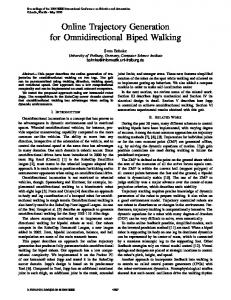
Fig. 1. Designed mirror over a box representing the robot body. We reported the dimensions of the mirror, its height, the height of the robot, the relative position of the center of the sphere constituting the spherical part, and the width of this. Measures are in millimeters.
this mirror lies in the possibility to select the pan angle to obtain a wide field of vision at will. Working with a spherical mirror, we have noticed that it doesn’t modify too much the shape of objects, but a large percentage of the image is useless for our goals because it contains the chassis of the underneath robot. The spherical mirror we adopted had a bend radius of 0.18 m centered at 0.67 m height from ground. The optical center was at 0.32 m from ground. With this system we obtained a vision field ranging more than 5 m in any direction, but the resolution (in [pixel/cm]) of the image obtained in this way was not sufficient for image processing. To give an idea of the resolution and the properties of the image reflected in this mirror, we give some data in the following table: Dist (m) PN DO (cm) R (pixel/cm)
where Dist is the distance from the mirror in meters, is the number of pixels in the image corresponding to a dimension of given in the third column. is the resolution the object in [pixel/cm]. Therefore, it was necessary to find a compromise between the bend radius of the mirror and the height where it was placed, avoiding an excessive reduction of the vision field, or its exaggerated opening with drastic reductions of the resolution. We have designed a mirror composed of a sphere intersecting a reversed cone, as depicted in Fig. 1. This shape allows exploiting the characteristics of the spherical mirror to a distance of 2 m, so the objects which fall in this range are not much deformed and have a satisfying resolution. The objects at a distance above 2 m are reflected in the conical part of the mirror, designed to allow the identification of objects at a distance up to 5 m with sufficient resolution. Although the conic part of the mirror can show more distortions, this allows obtaining higher
PN DO (cm)
R (pixel/cm)
When designing the mirror we also had to take into consideration the dimension limits imposed by RoboCup regulations. So we have obtained a mirror smaller than the previous, spherical one without reducing the range of vision and succeeding in positioning the mirror at a lower height above the camera. The spherical mirror employed before had a diameter of 270 mm and a bend radius of 180 mm. It was placed at a height of 330 mm from the camera, which was 320 mm from the ground. The new mirror has a diameter of 178 mm and the spherical part has a bend radius of 66 mm; it is 160 mm from the camera and 480 mm from the ground. With the spherical mirror we succeeded in obtaining resolutions of 0.26 pixel/cm at a distance of 4 m, with the new mirror the resolution is doubled, achieving 0.5 pixel/cm. Indeed, the maximum range of the mirror is above 5 m to include in the supplied image the walls limiting the field, which are 0.5 m high. The camera is a low-cost card camera, with a view angle of about 60 . A typical image taken from the sensor we have designed is shown in black and white in Fig. 3. In white, at the center of the image the body of the robot, on the left a computer video, on the top part of the image a ball and other robots. The black and white marks come from the elaboration discussed in the next section. IV. IMAGE PROCESSING In this context, image processing should give to the robot control system, in real time information about the position of different identified objects and self-localization. Working on images of 640 640 pixels where each color can change on 255 levels, we immediately noticed that in applications which require a steady image flow at a rate of at least ten frames/s we had to process a considerable data flow. To achieve this speed by employing the common image processing and computer vision techniques, it is necessary to add knowledge and provide smart algorithms. Taking hints from biology, we have designed an image processing system based on the concept of receptor. The generic term “receptor” is used for any biological unit able to receive stimuli from the outside environment and to transform them in nervous impulses which are transmitted to the central nervous system. In the innermost coat of the eyeball globe we find the retina, where, together with the different kinds of nervous cells, there are receptors sensitive to light. These receptors with a peculiar shape are named cones and rods. The first are specialized in the day color vision; the second are dedicated to the twilight, black and white vision. The vision system we have designed first estimates the likely position of the possibly interesting objects on the image, and, in a second phase, processes the pixels surrounding these points to recognize the nature of the objects and to detect their correct location. The idea of receptor is applied during the first processing
BONARINI et al.: AN OMNIDIRECTIONAL VISION SENSOR FOR FAST TRACKING
511
which allows us to discard the undesirable objects and increase the processing speed. Each receptor is composed of a 3 per 3 pixel matrix and it is characterized by three color parameters: and These are computed as follows: (1) (2) (3) and are the average values of the Red, where Green, and Blue components, respectively, of all the nine pixels; is the average intensity of the receptor (4) Fig. 2. Typical image taken by the sensor. The marks on it represent the receptors corresponding to the different classified targets (see below).
Fig. 3.
All the receptors for the RoboCup environment.
stage. To determine approximately the location of the different objects, it is useless to work on all the pixels in the image. We have devised a receptor mask so that no object can fall between two adjacent receptors without influencing at least one of them (see Fig. 3). This is possible, since we know a priori, in this semi-structured environment, the dimension of each object we are interested in. During a setup phase the system we have implemented receives from the user the parameters concerning the mirror shape, the typical dimension of the desirable objects and the colors to consider as reference. Then, it creates the receptor map which will be used for all the following processing activities. A ”prescanning” of the image with receptors gives an effect similar to that we would have when looking at the image through a sheet of paper on which has been punched a matrix of holes: possibly, we are not able to identify the objects and their dimension, but we could recognize their color and location. The ”pre-scanning” based on the receptors is a kind of image sampling. Acting on the location of the receptors we can obtain a sort of low-filtering
The receptor corresponds to one of the colors to be recognized if its three color parameters are close to those defined for that color. We have observed that carefully choosing the values of the sampling parameters, the system can recognize with a low error rate the different colors in different light conditions. This is mainly due to the filtering effect obtained by the above mentioned averaging operation. In other terms, it is possible to perform a reliable abstraction process, by classifying all the receptors as belonging to classes corresponding to the colors we are interested in. In Fig. 2, the classified receptors are drawn in black and white, with different shapes (dots, crosses, etc.). After having classified the receptors, we aggregate them in structures named targets. The creation of a target is possible through a sequential scanning of receptors, which become part of a target if they have expected characteristics of color and position, exploiting region-growing techniques applied to receptors. A target is a part of the image where one of the interesting objects might be present. Once targets are identified, it is possible to operate on the part of image defined by each of them (focus of attention) by adopting classical image processing and recognition techniques. In these final stages of the image processing we work on single pixels. We adopted the following technique:from areceptor belonging to the target we analyze pixels in a given direction. When we find a pixel with different color characteristics we are on the border of the region and we follow it by color gradient analysis, until we identify all its perimeter. We assume that there are no inclusions, as verified in the RoboCup environment. With this technique, we segment the target into groups of connected pixels. Each object silhouette correspond to a group, as does the background. In a second phase, we calculate the features of the groups (centre of area, moments of area), and, by matching these to reference parameters, we recognize the objects. The application of these techniques on the image portions identified in the first phase, and not on the whole image, gives a considerable reduction of the quantity of information to handle and increases the processing rate. It is evident that our receptor system has high benefits on the processing time. Having recognized the objects, we can compute their angular position and distance with respect to the agent. The distance is computed by mapping the distance in pixels in the image to the actual distance, given the mirror shape. Most of the activities
512
IEEE TRANSACTIONS ON INSTRUMENTATION AND MEASUREMENT, VOL. 49, NO. 3, JUNE 2000
in our application depend on relative positions of the objects on the field. We need to represent global positioning (and so, self-localization) only to communicate to other teammates this information. There are many approaches to self-localization [9], but their application hypotheses are not fully applicable in our environment, where the reference landmarks are continuously changing, due to occlusions. Details about our approach are not in the scope of this paper and will be presented elsewhere. V. SYSTEM PERFORMANCES Working directly on an image of 640 640 pixels, there would be 409 600 pixels to process. With our subsampling technique we consider 2500 receptors of nine pixels each, that is only 22 500 pixels to process. The number of receptors to be adopted depends on different factors such as the shape of the mirror and the minimum dimension of the objects to be recognized. For an effective setting a careful study of the mirror shape and the distribution of the receptors is needed. We have adopted a circular disposition of the receptors: the mask we have employed is composed of 20 rims of receptors, as shown in Fig. 3. The distance between the receptors and between the rims of receptors is optimized by the setup program on the basis of the information about the dimensions and the distances of the object. The time needed to control these receptors and to create the targets is about 1 ms. With about ten objects of different colors in the field, we have to add another 10 ms for the second image processing phase. This result has been obtained by using the PC on the robot, based on 300 MHz AMD K6 CPU, 32 megabytes of RAM, a Matrox Meteor II frame grabber and working with Linux RedHat 5.1 (Kernel version 2.0.34). These performances leave the bound to the image processing rate to the acquisition rate of the image, whose standard is 25 full frames/s. Moreover, since the image processing activity shares computation resources with control, planning and communication with other robots, the burden given by our algorithm can be considered really light, and does not require special purpose hardware. VI. CONCLUSIONS We have presented the hardware and software design of an omnidirectional sensor giving a mobile robot the possibility to track environmental elements present in any direction, with a frame rate higher than 20 frames/s. The application that has pushed us to implement this sensor has been RoboCup, where the robot operates in a semi-structured environment with strong real-time constraints. Our system satisfies the requirements. The system we have implemented may be used also in other environments and for other tasks having similar requirements. The image processing approach is fast and reliable and may be successfully adopted also for surveillance robots and any other applications where it is important to track markers of a given dimension and with characteristic colorings. The mirror shaping approach is also interesting to design revolutionary mirrors to match user requirements. We are presently starting experiments with more complex shapes that take into account both the horizontal field extension, to identify objects on the ground at a large distance, and the vertical coverage, to identify objects in a vertical plane, such as edges generated by vertical lines, which are projected as radial
lines on the image. We consider the angular position of these lines both for self-localization and indoor navigation. REFERENCES [1] D. Nardi, G. Clemente, and E. Pagello, “Art azzurra robot team,” in RoboCup’98: Robot Soccer World Cup II, M. Asada, Ed. Berlin: Springer Verlag, 1998, vol. D, pp. 467–474. [2] H. Kitano, M. Asada, Y. Kuniyoshi, I. Noda, E. Osawa, and H. Matsubara, “A challenge ai problem,” in AI Magazine, 1997, vol. 18. [3] M. Asada, RoboCup-98: Robot Soccer World Cup II. Berlin: Springer Verlag, 1998, vol. D. [4] M. Asada, H. Kitano, I. Noda, and M. Veloso, “Robocup: Today and tomorrow—What we have learned,” Artif. Intell. J., vol. 110, pp. 193–214, 1999. [5] Y. Yagi, S. Kawato, and S. Tsuji, “Real-time omnidirectional image sensor (copis) for vision-guided navigation,” IEEE Trans. Robot. Automat., vol. 10, no. 1, pp. 11–22, 1994. [6] E. Mouaddib and C. Pegard, “Localization using omnidirectional vision,” in ICAR’95. Piscataway, NJ: IEEE Press, pp. 133–138. [7] J. B. Gregersen, “A system for 360 vision in robot soccer,” Ph.D. dissertation, RMIT, Melbourne, U.K., 1998. [8] S. Suzuki, T. Katoh, and M. Asada, “An application of vision-based learning for a real robot in robocup learning of goal keeping behavior for a mobile robot with omnidirectional vision and embedded servoing,” in RoboCup’98: Robot Soccer World Cup II, M. Asada, Ed. Berlin: Springer Verlag, 1998, vol. D. [9] J.-S. Gutmann, W. Burgard, D. Fox, and K. Konolige, “An experimental comparison of localization methods,” in Proc. IEEE/RSJ Int. Conf. Intelligent Robots and Systems, 1998.
Andrea Bonarini was born in Milan, Italy, in 1957. He received the Laurea (Master of Technology) in electronics engineering in 1984 and the Ph.D. degree in computer science in 1989, both from the Politecnico di Milano. He is Associate Professor at the Department of Electronics and Computer Engineering of the Politecnico di Milano. He has been a member of the Politecnico di Milano Artificial Intelligence and Robotics (PM-AI&R Project) since 1984. He is a founding member of the AI*IA (the Italian Association for Artificial Intelligence), and among the founders of the IEEE-NN Council Italian RIG. He is coordinating the PM-AI&R Lab, where he has developed several Autonomous Mobile Robots. He is also participating in the Robocup effort (middle size league) with the Italian National Team (ART). His research interests include behavior engineering, navigation, data interpretation and control for autonomous robotic agents, mobile robot design, reinforcement learning and fuzzy systems.
Michele Lucioni was born in Tradate, Italy, in 1973. He received the Laurea (Master of Technology) degree in electronics engineering in 2000, from Politecnico di Milano, Italy. His research interests include vision and autonomous robots.
Paolo Aliverti was born in Tradate, Italy, in 1973. He received the Laurea (Master of Technology) degree in telecommunication engineering in 1999 from Politecnico di Milano, Italy. His research interests include vision and autonomous robots.