An OO Framework for Configuration of Deployable Large Component based Software Products N oure d d ine Be lkha tir,Pie rre -Yve sCunin,V incentLe stid e a u,Hacène Sali Adele Team Bat C LSR-IMAG , 220 rue de la chimie Domaine Universitaire, BP 53 38041 Grenoble Cedex 9 France
E-mail:
[email protected] Abstract Software Deployment is a new field of SCM which encompasses the post development activities (configuration, installation adaptation and activation) of a software product. Component based Software and the Internet offer new research issues. The new challenge is the automatic execution and management of this process. Based on this, deployment processes can be enacted and monitored in an efficient manner. In this paper we try to clarify the issues involved in Software deployment process and mainly on model requirements to describe environments, dependencies and requisite actions. The context is Software products based component. As part of a large system we are building, we consider in this paper the requirements for the first step of this process related to configuration issues. This kind of software introduces new complexities to configuration management. We propose a model to describe and (re) configure software for delivery and a configuration process with self-check so that the intended configuration is correctly built before delivery. These are provided by an OO framework we implemented. 1. Introduction The recent software engineering technologies, and in particular those related to component based software, have highlighted an important part of the software life cycle known as deployment. This part was only partially identified and understood, shadowed by other aspects, reducing the global management of this activity. In fact, some available ad hoc solutions provide only a limited support for the deployment or restrict its vision that becomes centralised, less automated. However, the deployment as an activity within the software life cycle is related at different degrees to several mature technologies such as Installation, software description which have been independently developed.
The complexity of the deployment is tightly related to the complexity of the current software. Factors of complexity are: a) Software Architecture: several architectures with needs to interoperate, different views of the software (component, module based… ) b) The configuration: Availability of several software configurations. c) Versioning system: Different versions for different needs. d) Diversity of sites: the well functioning of an application is related to the type of the execution sites, their software and hardware configurations. e) Enterprise organisation: the deployment should adapt to the enterprise structure, due to the dependency of the software configuration to the final user needs and restrictions. The management of these aspects within the same activity requires strong and interoperable models. Such as: Application model: describes the dependencies of the software, its different available configurations and versions… Enterprise model: describes the organisation of the enterprise, its different elements as well as its responsibilities, rights… Site model: describes the hardware and software features of the sites, allowing the selection of a right configuration to install.
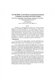
Figure 1 : The Deployment and the related technologies
1
software in order to take advantage of the new feature. The software producer and the client appear to be the main elements in the deployment activity. Nevertheless, in an environment of huge software, providing personalisation and extension features (API, specific language), an intermediary level has to be considered: the Enterprise. In fact, the enterprise can make changes in the software through customisation or extension; the result of these processing represents the actual software to deploy. Therefore, the physical preparation of the deployment is done at this level; furthermore, the enterprise policies and its organisation have to be taken into account.
Process model: describes the deployment process and the strategies to use. The frame of our work is the hierarchical component-based software that considers a composition of components as a new component. As a consequence, a component can be constituted with a number of components; each of which can be further decomposed. This approach allows a better reuse and abstraction level . Our focus concerns, particularly, the configuration phase during the deployment, i.e. the selection of valid configurations and implementations to install on the targeted sites, after a user command or introspection of the user’s site. Our concern is the first step of the deployment process i.e. the software configuration
In addition, the cooperation of different economical entities in the frame of a common project (example, bank, distribution… ) introduces a new type of entity related to a particular economical activity, “Virtual Enterprise” which requires its members to be either the same or complementary software needs. [1] Some existing technologies related at different degree to the producer, the enterprise and the client accomplish partially the activities related to the deployment. Figure 2 highlights the elements and activities related to the deployment [2]
This paper is structured as follows: The first section is mainly about the presentation of the concepts inherent to large-scale deployment, then we position the configuration management [7] within the deployment life cycle. The second section is dedicated to the description of the state of the art in the deployment, we detail precisely two types of proposal, a general one and a specific to the components. We synthesise the interesting concepts provided by those solutions. After presenting our approach and the adopted model is provided in the third section, we describe. the developed prototype. Finally we discuss our conclusion and future plans. 2. Large scale deployment
Figure 2 : Elements and activities related to the deployment
This part of the document discusses two main points: * The general deployment concepts where we identify the main elements acting within the deployment and the models required to perform a large-scale deployment. * The software configuration management and the deployment: we will explain its position with a deployment environment. 2.1. General concepts of the deployment : Recently the deployment was limited in its coverage to the installation and desinstallation of software [2]. The development of Internet and the increase of software complexity have highlighted the deployment as an activity within the software life cycle; this positions it as an important post development process between the software producer and the final client. The deployment activity is not limited to the installation, but it extends to all the software life span, including change management [4]. For instance, a hardware extension (memory extension) could lead to reconfigure previously installed
The deployment activity is decomposed into several sub activities, which are: 1) Activities related to the producer : After the development of the software, the producer is in charge of the packaging of the application and informs the different clients of the availability of the (new) version, to do so, two strategies are available :
2
Other strategies can be imagined based on these basic ones.
PUSH: In this case, the producer realises the transfer of the application without any request needed from the client;
3) Site Activities: it stands for the level where the software becomes ready to be executed. The site should provide information and actions to the deployment process. Such as: a) Means to perform the software installation and the update of the environment. b) Provide description information of the software and hardware configurations.
PULL: The client requests explicitly the transfer of the software. At this level other aspects are needed to complete the deployment namely: The application Model: it consists of object description that constitutes the application, their properties and roles in addition to the description of the needed execution environment. This environment is described trough a set of software and hardware dependencies. During the deployment, this information will be matched to those extracted from the site, in order to realise the selection of valid configuration.
2.2. Software configuration management and deployment The software configuration management is the field of software engineering that controls the software systems evolution (versions, configurations.). The software configuration insures the identification, organisation and control of the modifications that affect the software.
Configuration management system: This type of system should allow the selection of a “Valid” configuration according to precise requests. 2) Enterprise activities: the Enterprise level, being intermediary, insures both tasks related to the producer and the client. In fact, on one hand, it is considered as a client, with respect to the producer’s view, when transferring the application and on the other hand, as a producer, with respect to the users view, when customising and extending the application. Nevertheless, some aspects are exclusively related to the enterprise, namely : The Organisation: In a company employees’ software needs are heterogeneous, valid configurations for some of them are not for others (a development position and a commercial position have different needs). Thus, an organisation model for the description of users or groups of users’ rights is required in this deployment phase.
The main activities of the software configuration are: ? ? Identification: defines the structure of the software product. It allows defining the components and their types, making them unique and accessible (during a selection). ? ? Control: controls the versions and the modifications. ? ? Validation: insures the coherence and consistency of the proposed configurations. In a deployment environment, the configuration management is positioned before the software transfer and its installation/adaptation/update. The configuration manager insures the availability of a valid configuration. The configurations can be further restricted when installed on the client sites. The task related to construction of automatic configurations is based on aspects related to software description and software composition within a valid configuration. The construction of valid configurations should take into account the following facts: - Functional structure of the software: defines the modules/component relationships. - Dependencies : defines the dependencies of the software toward tools, documentation, … - Running environment: defines the running features of the software application. - Features: other type of information that could be used as selection criterion (language, state.)
Strategies: The deployment strategies between the enterprise and the clients are not only limited to Push and pull. Strategies should consider the enterprise organisation. Two complementary strategies can be proposed: Big bang: it consists in deploying at once the software to all the sites of the enterprise. Incremental: it consists in deploying the software through successive steps targeting a precise user group at each time.
Within the context of our work, the pursued objective is to adapt the automatic construction of valid configurations of architectures based on a
3
hierarchical component model. This configuration construction is a basement for the component deployment.
3.1.3. Configuration management with software dock
3. State of the art In this part, we discuss two types of deployment solutions: - General deployment solutions: depicted by two tools, the first, academic, is the Software Dock [5]. And the second, from the industry, known as Tivoli [6]. - Deployment for component based software: CCM will be discussed.
Software dock, insures some aspects of the configuration management (resolution of dependencies, selection based on a set of criteria...). The main means for the configuration management in DSD are:
3.1. Software Dock Software dock has been developed in the University of Colorado. The aim of software dock is to provide a general solution for the deployment life cycle. It allows describing, using the DSD (Deployable Software Description) formalism, a number of valid configurations. The deployment activities (installation, adapt, update) are provided by agent based software, some of them can be mobile.
Generally the composition rules allow to infer some valid property values. The guards are used to define whether or not an artefact has to be selected within a configuration.
-
Composition rules Guards.
Composition rules A composition rule is an expression of properties of the type if then . The condition is a logical expression between properties. The action allows to define a set of valid property values and other values to be rejected. Further it defines four types of actions:
3.1.1. Software dock architecture The software dock is based on three levels ? ? Field dock: this dock depicts the client side. It provides an information base that describes the software and hardware environment. The description is provided through XML DSD files. ? ? Release Dock: it represents the producer that publishes new software releases. ? ? Interdock : this level defines an organisation positioned
Excludes when the condition is true, the concerned property should be set to its disabled default value. Includes: the targeted properties should be set to their default enabled value. One of: one of the targeted properties should be set to its enabled value.
3.1.2. Software description model The Deployable Software Description is an application model. It allows describing: ? ? Software composition : Artefacts of the software ? ? Dependencies: It defines the dependencies of our software with other elements (libraries). ? ? A set of valid configurations: this is done through composition rules, which dynamically allow selecting or rejecting artefacts. This leads to producing valid combinations of artefacts considered as valid configurations. ? ? Properties: the property is the basic element of the description. It defines a specific aspect of the software (example OS). To each property are associated enabled default properties and disabled default properties, both states are used for compositions. (see next part)
Any of: it the condition is evaluated to true, then zero or more of the listed properties may be enabled. Example: If (OS!= win && OS!=”WinNT” EXLUDES {Winhelp} This rules means that if the operating system is not Win95 and not WinNT, then the property ‘Winhelp’must be disabled. Guards The guard is a Boolean expression of properties. It allows or rejects an artefact in the process of configuration construction. The guard expression is compared to the set of property values produced from the composition rule processing, leading to selecting or rejecting a set of artefacts.
The DSD is based on XML.
4
The following aspects of DSD also allow the construction of configurations -
-
3.3. Corba Component Model (CCM) CCM, is a component specification issued by the OMG that is based on the concepts of CORBA distributed architecture. In the initial definition of Corba architecture, the aspects related to the deployment were ignored. The specification was exclusively oriented towards the object interoperability.[3] However, in the new component specification, the OMG has given a great importance to the software deployment and distribution. In fact, the specification includes a deployment model allowing to describe component assemblies, which realisation is made at the last time.
Constraint: a constraint is a boolean expression of properties. It expresses a dependency of the software toward hardware or software aspects. When it is false, the selection process is stopped. A constraint can be defined as a non-resolvable dependency. Dependencies: defined mainly as a software dependency that can be resolved during the installation.
3.2. Tivoli Tivoli proposes a global network and software management solutions. The deployment is considered as a part of software management. Among Tivoli products, two software are related to deployment: Inventory and Software distribution. [6] The deployment activity lays on the facilities provided by the communication structure (Framework management) which insures both the communications with the sites and the deployment information storage (site configuration.) The deployment process is decomposed as follows: 1. Sites inventory : gather software and hardware configuration of sites; 2. Distribution: After the selection of sites by mean of a request, the administrator transfers the software to the selected sites. AMS (Application Management Specifications) is the software description language adopted by Tivoli. It is based on CIM (Common Interface model) model of the DMTF (Desktop Management Task Force) [9].
3.3.1. Overview of the model : Three models constitute the Corba3.0 standard, which is tightly related to EJB. Abstract Model: Describes the abstract view of the component. Constituted with a set of: Facet, Receptacles, event sources and sinks, properties and attributes. The component is described according to: ?? ?? ??
Provided services : Facets, each of which represents a realisation of an interface by the component Requested services: Receptacles, define the needed facets. Event sources and sinks
The components are assembled according to the facets-receptacles and event source-sink correspondences. Deployment model: defines the software composition, and the valid execution environments (Containers, and sites). The model uses OSD standard (Open Software Description).
AMS model The AMS model allows the description of the software granularity (component, files.) and its interaction with its environment (Environment dependencies). The model presents the software at different levels of details, from the general view to the elementary component description. A description file describes a unique configuration of a software.
Container model: defines the container that offers non functional services to corba component trough standard API. 3.3.2. CCM component deployment In the CCM view, the component deployment phase is positioned between the development (Component and container design) and the real execution of components on the servers. This phase is fundamental in the software life cycle. In fact, it corresponds to the part where the execution options are made effective and the software is composed. The deployment unit is the package, which contains the different implementations to deploy and the deployment descriptors.
Tivoli proposes an ‘enterprise’ oriented deployment solution restricted to a predefined process. ‘Select sites, transfer software’. The AMS model does not allow to describe different configurations of a software.
5
instantiation then configuration on the targeted sites. These steps are summarised in the following:
The process of the development of a CCM component is shared between five positions. Each one has, more or less, influences on the deployment through the generation of a set of descriptors. -
-
-
-
1.
Designer: defines the abstract view of the component. At this level a Component Descriptor is generated form the abstract view. Developer: performs the development of the component functional part. A set of implementation of the same interface can be provided as a package. This package is described with a package descriptor. Provider: provides components with their descriptors. Architect: creates software through component assembling. He generates an assembly descriptor. Configurator: associates the non-functional aspects to the component to be deployed.
2.
3.
4.
Define and choose the deployment sites: can be performed with an inventory tool (Tivoli inventory). Installation of implementations: Check existence of already installed implementation. The installation is performed according to the information available in the software descriptor. Instantiate the Home then the component: The home is the access point for the client software, it represents the visible part of the component. Connect the components according to the assembly descriptor.
Synthesis The concepts defined by the presented deployment solutions have some global similarities, but diverge in some specific considerations. The divergence concerns mainly the way of describing what we expect to deploy. For Tivoli (AMS), the configuration to deploy is defined and is not subject to adaptation during the installation. Software dock (DSD) and CCM (OSD) allow to deploy a set of configurations. The final selection is done in the client side according to its features and needs.
Four descriptors related to a special type of package, describe different views of the software. Software Package Descriptor (.CSD) : Describes the implementations of the component, and software and hardware dependencies of each one. Corba Component Descriptor (.CCD): Describes the component features needed for the design and deployment phases. The descriptor shows the abstract view of the component that can be used to assemble the component with a graphic tool. Furthermore, the descriptor allows to describe the non-functional services needed in the server, which are made effective at the end of deployment.
4. Our Approach 4.1. hierarchical component software The component-based technologies have emerged as the current leading software development architecture. These technologies provide a high level of abstraction and reuse, thanks to the mechanisms of events and the distribution of the tasks (functional and non functional aspects… ), issuing interoperability of components provided by different sources. Several effective proposals or under specifications are available such as Java Beans, EJB, CCM (Corba Component Model) These technologies are based on declarative descriptions of the component, equivalent to interface contract between a client and a server. This description is a type of software model (see CCM). The frame of our work is an expansion of CCM that has been proposed by our team. The expansion consists in introducing a new dimension to the model, known as the hierarchical concept. The abstract view of a component in the new model is equivalent to CCM.
Assembly descriptor: describes generally the software through the connections between the interfaces (facets-receptacles, sink-sources). It can be seen as instantiation and interconnection ‘pattern”. Property file descriptor (.cfp) : This descriptor allows to initialise the execution attributes on the component server. Deployment process: The goal of deployment, in the frame of distributed component software, is to match a software structure to physical execution sites. In CCM, the deployment is realised through available ORB services and deployment tools. The deployment tool uses ORB services to perform component transfer, installation, assembling,
6
A Component provides: A set of facets: A facet is the implementation of a set of methods (Interface in Java). It can be defined as “What the component provides as services” A set of receptacles: each one has to be combined with a corresponding facet of another component. It can be defined as “What the component requires as services” A set of event sources: points of event emission A set of event sinks: points of event reception A set of attributes: to allow the customisation or the initialisation of the component. A base reference: allowing the navigation between the ports. Figure 3 illustrates the abstract view of a component:
Figure 5: Composition and externalisation
Externalisation performs the correspondence between the new abstract view of the component and the abstract views of its constituents. It associates some ports of the constituents to those of the new component.
Figure 3: Abstract view of a component
4.1.1. hierarchical component architecture The starting point of the development based on components is the interface. Developers add new implementation in accordance to the contract defined by the interface. During the development of a component, it is possible to define intermediary states, i.e. not completely defined. At this level, for example, it is possible to compose an interface with a native component or other interfaces. The intermediary level that points interfaces can be further defined, though making references to one of its implementations. The concepts on which our component model are based are described on the simplified following model (figure 6):
A component software, is the result of a construction of component compositions through making a connection between corresponding receptacles and facets, and/or event sources and sinks. Figure 4 illustrates a composition. Figure 4: A composition
Figure 6: hierarchical component Architecture
This task can be performed, as in Java beans, through a composition graphical tool (Bean Box), increasing the reuse level. The approach of our team is to consider a composition as a new component that encapsulates its members. Each internal component can be either native (a set of java classes) or further composed. This type of composition requires a new concept known as externalisation.
In the above model two main concepts are shown:
7
A. Entities 1. Interface : This entity defines the abstract view of an entity (abstract component) 2. Implementation : it implements an interface and is either : ? ? Native : Code (Classes JAVA) ? ? Composite: the composite entities can be composed of interfaces or implementations (native, composite) or both. B. Relations 1. Implements : the implements relation creates an interface-implementation relationship 2. Refines: creates relationships between implementations. It is responsible for specialising the interfaces within the internal composition. The previous two relations are explicit in the architecture. They allow new components to be created. We name these kinds of relations “Creation Relations”
this activity depends on other relations associated to users’ needs (e.g. associated object). Therefore, the open feature of the system and its adaptability to new relations and/or structures are important factors. This has led us to propose an object oriented Framework insuring the adaptability of the selection whatever structures and relations are exhibited. However, some aspects related to coherence verification and immutable concepts, are completely integrated in the Framework. In the remaining part of this paper, a description of the proposed framework is given. The main part of the framework is the annotation part, through which it is possible to denote the entities of the architecture with a set of attributes. Example: Implementation1 is annoted with System = Linux Language = Java or C++ Architecture = RISC Memory >16 Mo. 4.2. Deployment of hierarchical component based software In our approach, the beginning of deployment matches with the end of the development phase and lasts until the software deinstallation. Thus, we consider the deployment as a “daemon”, adapting to further evolutions of the software, site and enterprise.
We can also state the following relatively implicit relation 3. Occurrence relation: it depicts the notion of component within a composite component. It is needed when creating a composite component either trough ‘Implements’ or ‘Refines’ relations. We will call this type of relations “browsing relation” or “dependency relation”.
The development architecture highlights the dependencies between the software elements. Thus it is a suitable basement for the deployment. In CCM and EJB, the dependencies are expressed within the descriptors. The descriptors are thus dedicated to two tasks: architecture and valid running environment description.
4.1.2. Associated Object
In the frame of the deployment, we have introduced, a new relation, which is the relation of dependency toward elements that are not considered as components. These elements can be a set of documentation, help files, or software... The following model illustrates the dependency relation between the entities and the associated object (entities that are not component based).
The hierarchical component model architecture is our basement for the deployment of component. 4.2.1. Annotation system for the deployment
In order to keep a high degree of independence between the component model and the deployment system we have adopted an annotation system. His annotation system is linked to the model allowing its components to be described.
Figure 7: dependency relation with associated objects
Annotation: allows to describe a component of an architecture according to criteria related to its running environment (operating system..) and its own information (language, version..) The deployment is not only related to the relations of the hierarchical component model. In fact, the deployment is dependent on other relations (Associated Object for example). The user can define these relations according to his needs. Thus,
The deployment in our view is not only related to the previous development architecture (Implementation and refinement relations). In fact,
8
Figure 9: dependencies between attributes
the annotation model should be as much flexible and open as possible to support user’s extensions. The proposed way to gain flexibility is an object oriented Framework. This Framework is the basement for building configurations. It encapsulates the general behaviour expected from an annotation system dedicated to the deployment and offers extension possibilities for the user to adapt it to her/his actual needs. 4.3. Annotation model 4.3.1. Introduction
The entities of the hierarchical component model are linked with a relation (implements, refines ..). These relations bear a certain semantic which is at least a dependency relationship. The annotations that describe these entities should express this relationship as depicted in the following figure.
4.3.2. The model
The following simplified model shows the general concepts underlined by the framework. Figure 10: Simplified annotation model
Figure 8: dependencies between annotations
Annoted object: is associated to the objects that could be selected (Interface, Implementation, Associated Objet… )
For instance, an implementation that refines another should have some properties dependent on the other such as supporting the same operating system or being developed by the same team.
Annotation: is defined by its attributes and methods. These annotations are exploited during the selection phase. However, the selection is not limited to annotation verification, other elements should be added. Among them, constrains and guard expressions, that allow to express the relations between the attributes, request and environment variable. The annotation type is tightly dependent on the element to which it is linked. In fact, when annotations belong to the same branch, it appears natural to define them with the same set of attributes or to organise them according to a hierarchy. Two solutions are proposed: Define a heritage hierarchy between annotations (associate types to annotations) or define an annotation with a set of attributes (list). The first solution allows a better coherence verification between annotations. However, it reduces the
The dependency is based on two aspects: - Annotation propagation: during the development base construction, annotations are propagated according to the link relation. - Annotation coherence: the semantic attached to a relation defines the coherence between the annotations. However, annotations are a set of attributes such as supported operating system, author… These attributes have heterogeneous behaviours and semantics. It is clear that the author attribute has a different propagation scheme given by the operating system. Thus it is necessary to reduce the granularity of the dependency to the level of the attribute, as shown in the following figure:
9
user’s flexibility, requiring to define annotation type for each new attribute.
4.4.1. Attribute class
new
Figure 11: Attribute heritage example
Attribute: An attribute is defined by its value (typed) and a propagation method which shows its influence on its descendants. Definition: Attribute ATTR member of Annotation AnnotB linked to entity EB is said descendant of Attribute ATTR member of Annotation AnnotA linked to entity EA, if a direct or transitive relation between EB and EA exits. Example EB implements EA. The father relation is a particular case of descendant, which is a direct descendant.
Attribute Value : Object Relations : List Initialisation() Object getValeur() setValeur() addRelation() Relation getRelation() Affect() Compare()
The influence of an attribute on its descendants is related to the relations between them. This is defined through a set of strategies that allow to effectively realise the descendant relationship.
AttLanguage Value : Tlang
AttSystem Valeu : Tsyst
OperationX() OperationY()
Operation1() Operation2()
The attribute class, defines the data and the basic logic of an attribute namely: ? ? Its value ? ? List of type of relations related to the attribute. The type of relation is dependent on the nature of the entity defined by the attribute. ? ? The initialisation method: used to initialise the value of the attribute according to its father’s value and the relation/strategy linking them. The user can define new attributes, through heritage and overriding the properties (type, value), methods and/or appending other methods related to the new attribute. For example: for the attribute AttSystem that describes the valid operating system. The type of value can be overridden to Tsyst type that is more specific to describe operating systems. It is possible to append new methods.
Relation: The entity relation associates an attribute to a set of relations (Refines, implements… ). These relations are either mutually exclusive (example refines and implements) or concurrent, in this case, only one is considered as a creation relation, others are considered as a browse relation. The creation relations, in the case of the component model, are: Implements, Refines, Depends. They represent the minimum set of relations to define a tree structure of the model. It is possible to associate a semantic of influence between attributes with each relation. As far as the Implements relation is concerned, it is possible to decide to completely copy the father value to its children accessed with this relation.
We distinguish three types of attributes according to their influence:
Strategy: a strategy is a set of actions dealing with the influence of an attribute toward its children. Example: Strategy of propagation with affectation: copy the value of the father to its children.
-
Local: the attribute has only a local effect. Its descendants don’t have any relationship with it. Example: component creation date
4.4. Framework The choice of the Framework design is a matter of user’s need to provide flexibility. The Framework encapsulates a customisable behaviour of propagation and coherence of attributes.
-
The framework is based on three classes: Attribute, relation type and strategy.
-
Frozen: beginning from the position where the attribute is set to frozen, its descendant values are not subject to any modification.
Example: Language, in a certain policy, we decide to accept only components written in java.
10
Contextual : the value of the descendant attribute is calculated according to the strategy that links it to its ascendant
Example: Operating system; the child attribute is initially assigned the value of its father. 4.4.2. Relation Figure 12: Heritage example for relations Relation
Creation Relation
Browse Relation
Verifiable : Boolean BrowseRelations : List
Refine Relation Calculation : StrategyCalcul Verification : StrategyVerif
Implement Relation Calculation : StrategyCalcul Verification : StrategyVerif
Composite Relation
Verification : StrategyVerifComposite
The relation class allows to define the influences that it carries. The attributes are in fact implicitly linked with the same relations linking the elements they describe. See the following figure:
4.5. Configuration construction The latter defined framework is a static information base dedicated to the deployment. However during the process of configuration construction, dynamic relationships have to be taken into consideration. They depict knowledge gained on the software domain. This knowledge is expressed through selection constraints; e.g. if the OS!=win then the help file should not be a .hlp. This type of knowledge is not carried by the current framework definition. 4.5.1. Selection constraints
We distinguish two types of relations: 1. ‘’Creation’’ relation: the creation relation is used to create new components. We have identified three relations related to the component system (Implements, Refine, Depend). The creation relation has to enforce the mutual exclusion policy. 2. “Browse” Relation: These relations are constituted after the creation of a component (ex: composition relation). Some coherence verifications should be conducted through these relations.
The selection constraints are used during the construction phase. They define the behaviour of rules related to the construction of configurations. The constraint is an expression of the form . The condition references a set of attributes in a boolean expression. The action is performed when the condition is true. The action defines values of attributes included or rejected during the process of constructing configurations.We define two states: Includes: this state means that the attribute values have to be found in the annotation of any component member of that configuration. Excludes: none of the selected configurations should have the value of the attributes that have been excluded.
The attributes are linked through instances of each potential relation. 4.4.3. Strategy
The strategy class defines the mechanism of influence between attributes. The user can define different strategies using heritage mechanism. For example, the strategy of propagation with affectation is done through copying the value of the father to its children. We distinguish two types of strategies a. Strategies of propagation b. Strategies of verification The following figure shows the strategy [8]
Example: is OS!=win then excludes helpExtension =hlp. It expresses that if the operating system is windows then the helpExtension attribute should not be hlp. These constraints allow to set rules of coherence. 4.5.2. Result of the selection
The deployment addresses the issue of providing a common way of transferring/installing/updating.. software on heterogeneous platforms. Thus the phase of selection would concern the provision of a software to a set of different systems.
Figure 13: Strategy model
11
The following figure shows the Meta model:
Considering these facts, the result of selecting on the development base side should be the whole valid configurations. These valid configurations have to be provided with the description files (IDL) in order to operate on the component server. The whole valid configurations are organised on a package then dispatched on the targeted systems. On each target site, a process of selection should pick a right configuration. In order to allow this processing we propose to describe all the implementations, members of the package in a descriptor of OSD or DSD type.
Figure 14: Meta model
Entity
non root entity
Interface Annotation Implementation, associated object...
root entity
is linked
is linked
R2
5. Implementation In order to validate the proposed concepts we have implemented a Java prototype that performs: - management of the hierarchical component in a object oriented data base (ObjectStore) - annotation management and configuration construction - Framework of a user graphic Interface independent from the component and annotation models.
reference
reference
R1
Type of relation
Creation relation
Browsing relation
5.2.1. The Presentation framework
The objective of the graphical interface is to offer several views of the system. New views can be provided when the model is extended. The system should allow to perform dynamic links with the new view without intervention on the code.
5.1. Architecture The global architecture of the prototype follows the MVC separation of the data and the visualisation. It is implemented with JavaBean event facilities. The prototype has three major parts: - Configuration construction system: accesses to the data model and implements the annotation model and the selection algorithm Controller: insures an independent communication between the graphical interface and the data model. - Graphical User Interface: allows to visualise the data.
To realize this, we propose a system based on service provision (BeanConext). Each view provides a service related to a special relation or entity in the actual hierarchical model. The graphical system requests the names of new entities and relations defined in the hierarchical and annotation models and according to the result requests the right service. The naming of a service has to follow the naming of entities and relations. For example the Refines relation should be performed by the Refines service. The following Framework supports the service management:
5.2. Independent User Interface The annotation and the hierarchical component models being subject to modification and extension, the user interface should be constructed in ways that reduce the influence of those modifications. In order to reduce this influence, it is necessary to reduce the coupling between both systems. It is achieved through reducing the amount of shared information between them. To realise this, we propose a simple Meta model that depicts the common knowledge between both systems. This metamodel assumes that: There is a special entity, which is a root of the model (Interface) The entities are linked with relations that are either of creation or browsing type. The entities can be components, associated objects or annotations…
Figure 15: Graphical framework BeanChild Support
Type of service
BeanService Context
Service Provider Service storing() Service Request() Service Type Service
12
Service Proxy
Container
Container: insures the hosting of the beans and manages the services.
[1] Vincent Lestideau, Noureddine Belkhatir, Pierre Yves Cunin, Environnement de déploiement de logiciel automatisé centré entreprise, ICSSEA 2000-9
Service Proxy: manages the beans providing the same service Service provider: encapsulates the service management.
[2] T. Coupaye, J. Estublier. Enterprise Software Deployment: Foundations & Related Technologies. Laboratoire LSR. Grenoble, Octobre 1999.
6. Conclusion We have described the design and implementation of a kernel of a configuration management system adapted to the new specifications of deployable component based software. The contribution of this paper can be summarized as follows: - it describes a novel architecture for a deployment environment providing the functionality for automatic driven deployment execution and management. - It addresses in an OO and integrated framework various problems relevant to the description of deployable software - It discusses on model requirements to describe environments, dependencies and requisite actions to manage the deployment process. Further work remains to be done on several aspects. Our future plans are mainly in two areas. First, we intend to evolve the prototype into a (re) configuration management system that we can use. The second area of research is to expand the system. We plan to investigate the integration of enactable process technology with the configuration management system. Our experience suggests that configuration management combined with enactable process technology provide an excellent basis for a new generation of Software deployment environments.
[3] Raphael Marvie, La proposition unifiée « Du modèle d’objets au modèle de composants » LILF [4] R.S. Hall, D.M. Heimbigner, A. van der Hoek, and A.L. Wolf. An architecture for post development configuration management in a widearea network. In Proceedings of the 1997 International Conference on Distributed Computing Systems, pages 269---278. IEEE Computer Society, May 1997 [5] Richard S. Hall, Dennis Heimbigner, Alexander L. Wolf A Cooperative Approach to Support Software Deployment Using the Software Dock ICSE ’99, Los Angeles, CA (1999) [6] Web site Tivoli, www.tivoli.com [7] Software Configuration Management: State Of The Art, State of the Practice. LNCS 1675 .Estublier (Ed.) SCM’9 Toulouse France [8] Erich Gamma, Richard Helm, Ralph Johnson, John Vlissides, « Design Patterns », Edition Addisson Wesley, 1997 [9] Web site DMTF (Desktop Management Task Force),www.dmtf.org
7. References
13