RTAI-Linux operating system has been installed on the PC/104 to create the ... plicitly dedicated to the simulation and the control of the PUMA 560 robotic arm is ...
An Open Source Distributed Platform for the Control of the PUMA 560 Manipulator Gianluca Palli, Luigi Biagiotti, and Claudio Melchiorri Dipartimento di Elettronica, Informatica e Sistemistica Universit`a di Bologna Via Risorgimento 2, 40136 Bologna, Italy {gianluca.palli, luigi.biagiotti, claudio.melchiorri}@unibo.it Abstract In this paper, an RTAI-Linux based distributed platform for the control of the PUMA 560 robotic manipulator is presented. From the mechanical point of view, the PUMA 560, besides being one of the first and most popular 6-DOF anthropomorphic manipulator, is still a very good example of implementation of small size robotic arms. On the other hand, its original control system, if compared to modern controllers, is an old piece of computer science history. Our goal is to preserve the mechanics and the power electronics of the PUMA 560 and replace the original control system with a modern and flexible platform based on RTAI-Linux. A PC/104 embedded system equipped with two DAQ boards is used to manage the I/O signals of the robot and to control the low level security functions, bypassing the original Mark III controller, while the high-level controller and the user interface run on a standard PC. With the aim of comparing the behaviour of the robotic device with a simulation of the system, useful for task planning and fault detection, the controller of the robot communicates also with a real-time simulation of the PUMA 560 that runs on a third PC. These three real-time systems are based on RTAI-Linux, and RTNet is used for the implementation of low-latency deterministic network communications needed in distributed control applications. In the paper, after the description of the architecture of the proposed control platform, the performances of the system are analyzed with particular attention to the execution time of the various tasks, communication delays due to network communication and comparison between the response of the real and the simulated robot.
1
Introduction
of many free tools for the development of real-time applications, like RTAI-Linux, RTnet [3] and so on. For these reasons, with the aim of improving also the performances and the flexibility of the Mark III controller, the hardware control architecture of the PUMA 560 has been completely redesigned. Only the original power supply unit and the linear current amplifiers that drives the motors of the robot have been preserved. The low level control system has been replaced by a PC/104 industrial computer based on the Elan520 AMD microcontroller together with two Sensoray 526 DAQ3 boards. Since the Elan520 microcontroller is 486 compatible, the RTAI-Linux operating system has been installed on the PC/104 to create the new real-time control platform of the robotic manipulator. The connection between the PC/104 control unit and the robot drive box is realized by the TRC041 board set, produced by Trident Robotics [4], that provides all the analog
The PUMA1 560 is a 6-DOF2 industrial manipulator. It is for sure the most popular device of this type, and, besides having been employed for many years in industrial applications, it is now widely used by several robotic labs both for research and for educational activities. Due to the outdated interface and control system, we decided to replace the original Mark III controller [1, 2] with a modern control architecture. The large availability of low cost microcontroller based platforms for industrial applications allows the implementation of very flexible embedded systems for the control of automatic machinery and robotic manipulators. In this context, the adoption of open source software environments offers a valuable alternative to commercial solution, due to the availability 1 Programmable 2 Degree
Universal Machine for Assembly. Of Freedom.
3 Data
1
Acquisition Board.
2
The Hardware Architecture
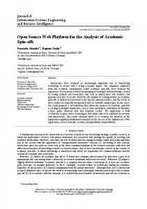
A scheme of the connection between the PC/104 and the PUMA drive box is shown in Fig. 1. All the components of the original Mark III controller have been removed form the drive box, and just the linear power amplifier that drive the axis of the robot and the power supply unit have been maintained. The TRC041 board set is used to collect all the I/O control signals into two buses, for analog and digital signals respectively. The torque applied by the 4 Ordinary
Differential Equations. Operating System. 6 Real-Time Workshop. 5 Real-Time
MAIN BOARD POWER LINES
SENSOR SIGNALS
AMPLIFIER BOARD
ENCODERS
PUMA560
POTENTIO− METERS
MOTORS
ARM CONNECTION BOARD DRIVE BOX
BRAKES
INTERNAL BUS
ANALOG BUS
DIGITAL BUS
ANALOG BUS
DIGITAL BUS
INTERCONNECTION BOARD
S526 DAQ BOARD
S526 DAQ BOARD
WRIST CONTROL END−EFFECTOR CONTROL DRIVE BOX CONTROL
TRC041 ARM CONTROL EMERGENCY FUNCTIONS
16bit ISA BUS
AMD Elan520 BOARD ETHERNET LINK
SERIAL CONSOLE
ETHERNET LINK
PC/104
and digital signals necessary for the control of the system. In [5], a similar architecture is presented, even though the control system is based on standard personal computer running the non real-time Windows platform. Another important feature that can be implemented in a modern robot control system is the realtime simulation of the manipulator behavior, useful for control system testing, task planning and fault detection. In particular, by running the real-time simulation in parallel with the real system, and by comparing the response of the two systems, it is possible to recognize unpredicted events, like collisions with unknown objects or actuator faults, and eventually stop the system to avoid risks and damages. The computing capabilities of modern personal computers can be easily exploited to perform both real-time control and real-time simulations of complex nonlinear dynamic systems [6], like robotic manipulators. In [7] the implementation of a real-time algorithm for the integration of ODE4 systems on the RTAI-Linux RTOS5 is reported, while in [8] the real-time simulation of dynamic systems generated by the Modelica environment is discussed. In this paper, a real-time integration algorithm [7] is used to compute the dynamics of the PUMA robot by solving its closed form Eulero-Lagrange model [9, 10]. Moreover, several tools are available for the design and the simulation of robotic systems, like the Robotic Toolbox [11] or RobotiCAD [12] for Matlab/Simulink, or ROBOOP [13] for the C programming language. In [14], a Simulink based toolkit explicitly dedicated to the simulation and the control of the PUMA 560 robotic arm is presented, while in [15] the generation of RTAI-Linux control applications from the open-source Scilab/Scicos environment is shown. In this paper, the Matlab/Simulink/RTW6 environment has been used for the design of both the high-level controller and the real-time simulation of the manipulator.
SERIAL CONSOLE
Figure 1: Scheme of the PUMA 560 control platform. DC motor to the joints of the robot are controlled by the linear power amplifiers and commanded by analog signals (±10 [V ] range). Absolute position information are provided by potentiometers connected to the joints (0 ÷ 5 [V ] range) and relative positions are given by encoder connected to the motor shafts. Other digital I/O signals for service and security functions are provided: through these signals it is possible to activate and to monitor the state of the drive box and of the joint brakes. The AMD Elan520 PC/104 platform (486 compatible processor at 133 MHz, 32 MB of RAM and 64 MB of storage flash memory) is used to acquire all the I/O signals by means of two Sensoray 526 Data Acquisition (DAQ) modules. Each DAQ modules has 8 ADC and 4 DAC channels, 4 quadrature encoder inputs and 8 programmable I/O digital ports. One DAQ module is used to control the first three joints of the arm (waist, shoulder and elbow) and to monitor the power and motor temperature emergency lines, while the other module controls the wrist joints and drives the digital lines for the end-effector opening/closure and the drive box enable functions. The PC/104 communicates with the development platform by means of an ethernet link and a serial console. The former interface is used for both non real-time and real-time data transfer, while the latter is used to setup the real-time environment and to manage the applications. The development platform is a standard personal computer with Pentium IV 3GHz processor and 1GB of RAM running on the RTAI-Linux RTOS. This PC is used both to develop the control and simulation
PUMA 560 INDUSTRIAL MANIPULATOR
REAL−TIME SIMULATION PLATFORM
EULER−LAGRANGE DYNAMIC MODEL
RTNET DEVELOPMENT & CONTROL PLATFORM
SIMULINK CONTROL SCHEME
PC/104
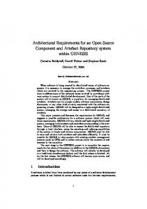
Figure 2: Architecture of the PUMA 560 distributed control system. applications for the PUMA 650 control system. It communicates, via ethernet using the real-time network layer RTnet, with the PC/104 described before and with the simulation platform. It is also connected through a null-modem cable to the serial interface of the PC/104. Also the simulation platform is a standard personal computer with Pentium IV 3GHz processor and 1GB of RAM running on the RTAI-Linux RTOS.
3
The Control System Structure
In Fig. 2 the structure of the open-source distributed real-time control system of the PUMA 560 industrial manipulator implemented in our lab is reported. Both the PC/104, the development and control platform and the simulation host have installed the Linux kernel 2.6.19.7, RTAI 3.5 and RTnet 0.9.9.
3.1
PC/104 Low-Level Controller
Due to the safety requirements of the manipulator control system and to the limited computation capabilities of the Elan520 microcontroller, the low level security functions are managed directly by the PC/104 together with the analog and digital I/O routines, while complex operations are executed by the remote control host. The low level controller is implemented in kernel space in the PC/104. The periodic execution of the control task is driven by a programmable hardware timer interrupt coming from one 526 DAQ board each 1ms, while emergency signals are managed asynchronously through dedicated interrupts. Moreover, a watchdog timer is used to
stop the robot in case of failure of the control system. Two different working modalities have been implemented in the low-level controller: joint torques control or joint-space PD position control. In the joint torques control mode, the data coming form the realtime network socket are interpreted as desired joint torques, and hence directly converted into the proper output voltage to drive the motor linear amplifiers. This working modality is suitable for the implementation of complex control schemes on the remote control platform. In the joint-space PD position control mode, the data coming form the real-time network socket contains the desired joint positions. A PD position control + gravity compensation is then used to drive the robot. In this case, the joint velocities is reconstructed from encoder information by means of state variable filters. In this modality, the trajectory data file can be also uploaded to the PC/104 and read by means of a dedicated application: the robot controller is made in this way independent from the rest of the system and in particular, form both the network and the serial connection. In both the two working modalities, the joint positions and some information about the state of the PC/104 and of the PUMA drive box are sent across the network to the remote control host.
3.2
PUMA 560 High-Level Controller Design
The high-level controller of the PUMA 560 manipulator has been implemented under the Matlab/Simulink environment and the Real-Time Workshop has been used to generate the real-time control application for the RTAI-Linux target. A dedicated S-Function block has been used to implement
the data transmission and reception over the realtime network. In this way, a very easy and flexible programming interface to the robotic manipulator is provided to the final user, and in particular to students. By changing, in the Simulink control scheme, the destination of the network data transmission, it is possible to test the behavior of the control application with the real-time simulated robot and, when the testing phase is passed, switch the control application to the real robot. The safety of the controller tuning phase is, in this way, significantly improved. Moreover, the control application and the real-time simulation can also run on the same machine, using the RTnet looppack device for data transmission. This software architecture can be also used for online robot task planning by using two independent controller, one connected to the simulated robot and the other connect to the real one. The manipulator activities can be then planned and tested on the simulated system also while the real robot is performing other tasks. The real-time simulated system can be also used for fault detection. In this case, the controller is applied simultaneously both to the simulated and to the real robot. From the comparison of the response of the two systems, it is possible to evaluate external loads applied to the manipulator, unexpected collisions with unknown objects or the occurrence of actuator faults [16, 17]. These information can be used to improve the safety of the robot, by stopping it or by disabling the joint torque commands and switching to the gravity compensation controller [18].
3.3
Real-Time Simulation PUMA Manipulator
of
the
In this work, the real-time simulation of the PUMA 560 is implemented with a periodic fixed step RTAI task, which executes all the operations necessary for the computation of the time evolution of the system. The dynamics of the robotic manipulator is modeled by usign the Euler-Lagrange formalism: M (q)¨ q + C(q, ˙ q)q˙ + Dq˙ + g(q) = τ − τf
(1)
where q is the joint position vector , τ and τf are the vectors of the torque and of static friction acting on the joints, M (q) is the inertia matrix, C(q, ˙ q) is the matrix of the Coriolis and centripetal effects, D is the viscous friction matrix and g(q) is the vector of gravity effects. In order to compute the time evolution of the robot state, the differential equation system defined by eq. (1) must be solved by means of a numerical integration algorithm over the period of the real-time
Integration step start
Save the state of the system Compute the new state of the system
Restore the state of the system
Evaluate the integration error and adjust the integration step interval no The integration step has been decreased?
yes
no
Integration time > Simulation step time? yes
Initial time + = Integration step time no Integration time > Simulation step time? yes
no
Initial time ≥ Final time? yes Return the new system state
Figure 3: Flowchart of the real-time integration algorithm. task. For the implementation of a variable-step integration algorithm, controls on the integration error, the step size and the execution time are introduced in order to avoid system starvation and to satisfy the real-time constraints. Therefore, it is possible to require the simulator to solve the dynamic equations with a given precision, in terms of relative or absolute error: if the period of the simulator task is too small to allow the computation of a solution with the prescribed error, the algorithm is stopped and the last available solution is returned. In Fig. 3 the flowchart of the real-time integration algorithm is reported. The simulation task period can be chosen equal to the period of the controller without problems: the error checking procedure can refine the integration step if necessary to satisfy the specifications on the integration error. The use of fixed step integration algorithms can introduce a large error drift in the solution of the system, since there is no control on the integration error. In this work, we have used different functions of the GNU Scientific Library (GSL) for the implementation of the numeric integration methods for solving the differential equations describing the system. Some modifications on the GSL library have been introduced to grant their real-time execution. With this changes, we can use the fixed/variable step integration algorithms available in GSL in the implementation of real-time simulation tasks. With the aim of simplifying the development of real-time simulation applications, the Matlab/Simulink/RTW environment has been used. For this purpose, the integration algorithm used by Matlab in fixed step applications has been replace with the proposed real-time integration algorithm into the code generated from RTW for RTAI target. The
−20 −40 0
5
10
15
20
25
30
Joint Positions Errors [deg]
5
Joint 2
Joint 2
Joint Positions [deg] 0
35
40
0
−5 0
45
5
10
15
20
25
30
35
40
45
5
10
15
20
25
30 35 40 Simulated Robot Error
45
5
Joint 3
Joint 3
200 150
5
10
15
20
25
Joint 5
100
30
35
40
5
Setpoint Real Robot Simulated Robot
50 0 0
5
10
15
20
25
Time [s]
30
−5 0
45
Joint 5
100 0
0
35
40
Real Robot Error
0
−5 0
45
5
10
15
20
25
Time [s]
30
35
40
45
Figure 4: Positions of the real and the simulated PUMA 560 Arm.
Figure 5: Errors of the real and the simulated PUMA 560 Arm.
PUMA 560 simulation scheme has been provided with the same real-time network interface used by the control application to allows the communication between these two systems. The parameters and the explicit dynamic model of the PUMA 560 used in the simulation scheme are not here reported for brevity. These information can be found e.g. in [9, 10].
the network transmission delay has been measured by means of a dedicated application. The best performances have been obtained excluding the TDMA7 control and reserving the access to the network interface to the real-time application only. In Fig. 6 the round-trip delay of network packets exchanged between the control platform and the PC/104 connected through a cross cable is reported. It is important to note that the transmission delay is quite always less than 100 µs. This networking framework is then suitable for the implementation of a closed loop control system with a sample time of, at minimum, 1 ms.
Experimental Results
The software architecture described in the previous Sections has been used for the simulation and the control of the PUMA 560 manipulator. The details about the robot control algorithm are not reported here for brevity and because is not the focus of this discussion. It is important to remark that the control application has been used, without any modification, for the control of both the real manipulator and the simulated one. The response of these two systems are reported and compared in Fig. 4 and Fig. 5. Fig. 4 shows the positions of the arm joints 2 and 3 (the most affected by the gravity terms) and of the wrist joint 5 while in Fig. 5 the tracking error of the same joints of both the real and the simulated robot. In particular, from these latter plots, it is possible to note that the behavior of the two systems is very similar. The small difference in the response between the real and the simulated robot can be ascribed to the (large) uncertainty on the joint static friction effects. A particular attention has been given to the measurement of the execution time of the various task. As expected, the robot simulation task is the more time consuming one. Nevertheless, in our experiments, the execution time of the simulation task never exceed the 400 µs, with a period of 1 ms. Also
100
95
Delay [µs]
4
90
85
80
75
1000
1500
Time [s]
2000
2500
Figure 6: Network packets round-trip delay, without TDMA control.
5
Conclusions
In this paper, the implementation of an open source real-time distributed control system for the PUMA 560 manipulator has been presented. The experimental results show the effectiveness of the proposed 7 Time
Division Multiple Access.
control platform and of the real-time simulation of the robot. This control architecture gives to the final user, and in particular to students, the possibility of programming the PUMA 560 through very simple and common tools, and provides a useful simulated testbed for the tuning of the control system and the planning of the manipulator activities. For future activities, a graphic user interface, running on the remote control platform, for the management of the PC/104 low-level controller functions is under development. Also a 3D graphic rendering of the manipulator on the simulation platform is object of future activities.
Acknowledgements A special thank to Ugo Fabrizi and Mauro Borselli for helping in the implementation of the PUMA 560 distributed control system.
References [1] P. I. Corke. The Unimation PUMA servo system. In Technical Report MTM-226, CSIRO, Automaiton Group, 1994. [2] Puma Mark III. VAL II, 500 Series Equipment Manual. [3] J. Kiszka and B. Wagner. RTnet - a flexible hard real-time networking framework. In Proc. of the 10th IEEE Conf, on Emerging Technologies and Factory Automation, 2005. [4] Trident Robotics and Research Inc. TRC041 Puma cable card set, 2007. [5] V.M. Becerra, C.N.J. Cage, W.S. Harwin, and P.M. Sharkey. Hardware retrofit and computed torque control of a Puma 560 Robot: Updating an industrial manipulator. IEEE Control Systems Magazine, 24:78–82, October 2004. [6] RT-MBDYN. Multibody dynamics analysis software on real time distributed systems. http://www.aero.polimi.it/~mbdyn/ mbdyn-rt, Online. [7] G. Palli and C. Melchiorri. Realtime hardware emulation for rapid prototyping and testing of digital control systems. In Proc. of the 4th IFAC Symp. on Mechatronic Systems, Heidelberg, Germany, September 12-14 2006. [8] G. Ferretti, M. Gritti, G. Magnani, G. Rizzi, and P. Rocco. Real-time simulation of modelica models under Linux / RTAI. In Gerhard
Schmitz, editor, Proceedings of the 4th International Modelica Conference, Hamburg, Germany, March 7-8, 2005. [9] B. Armstrong, O. Khatib, and J. Burdick. The explicit dynamic model and inertial parameters of the PUMA 560 arm. In Proc. of the 1986 IEEE Int. Conf. on Robotics and Automation, volume 3, pages 510– 518, San Francisco, CA, 1986. [10] P. I. Corke and B. Armstrong-Helouvry. A search for consensus among model parameters reported for the puma 560 robot. In Proc. of the 1994 IEEE Int. Conf. on Robotics and Automation, volume 2, pages 1608–1613, San Diego, CA, USA, May 8-13 1994. [11] P.I. Corke. A robotics toolbox for MATLAB. IEEE Robotics and Automation Magazine, 3(1):24–32, March 1996. [12] R. Falconi, C. Melchiorri, A. Macchelli, and L. Biagiotti. RobotiCad, a Matlab toolbox for robot manipulators. In Proc. of the IFAC Int. Symp. on Robot Control SYROCO 2006, 2006. [13] R. Gourdeau. ROBOOP: A Robotics Object Oriented Package in C++, 2006. [14] W.E. Dixon, D. Moses, I.D. Walker, and D.M. Dawson. A simulink-based robotic toolkit for simulation and control of the PUMA 560 robot manipulator. In Proc. of the 2001 IEEE/RSJ Int. Conf. Intelligent Robots and Systems, volume 4, pages 2202–2207, Maui, HI, USA, 2001. [15] R. Bucher and S. Balemi. Scilab/Scicos and Linux RTAI - a unified approach. In Proc. of 2005 IEEE Conf. on Control Applications, pages 1121– 1126, 2005. [16] A. De Luca and R. Mattone. Actuator failure detection and isolation using generalized momenta. In Proc. IEEE Int. Conf. on Robotics and Automation, 2003. [17] A. De Luca and R. Mattone. Sensorless robot collision detection and hybrid force/motion control. In Proc. of the 2005 IEEE Int. Conf. on Robotics and Automation, 2005. [18] A. De Luca, A. Albu-Sch¨ affer, S. Haddadin, and G. Hirzinger. Collision detection and safe reaction with the DLR-III lightweight manipulator arm. In Proc. of the 2006 IEEE Int. Conf. on Intelligent Robots and Systems, Beijing, China, October 9-15 2006.