Energies 2014, 7, 3086-3103; doi:10.3390/en7053086 OPEN ACCESS
energies ISSN 1996-1073 www.mdpi.com/journal/energies Article
An Optimal Reactive Power Control Strategy for a DFIG-Based Wind Farm to Damp the Sub-Synchronous Oscillation of a Power System Bin Zhao 1,2, Hui Li 1,*, Mingyu Wang 1, Yaojun Chen 1, Shengquan Liu 1, Dong Yang 1, Chao Yang 1, Yaogang Hu 1 and Zhe Chen 3 1
2
3
State Key Laboratory of Power Transmission Equipment and System Security and New Technology, School of Electrical Engineering, Chongqing University, Chongqing 400044, China; E-Mails:
[email protected] (M.W.);
[email protected] (Y.C.);
[email protected] (S.L.);
[email protected] (D.Y.);
[email protected] (C.Y.);
[email protected] (H.Y.) Sichuan Electric Vocational and Technical College, Chengdu 610072, China; E-Mail:
[email protected] Institute of Energy Technology, Aalborg University, Aalborg East DK-9220, Denmark; E-Mail:
[email protected]
* Author to whom correspondence should be addressed; E-Mail:
[email protected]; Tel./Fax: +86-23-6510-2441. Received: 26 February 2014; in revised form: 23 April 2014 / Accepted: 24 April 2014 / Published: 5 May 2014
Abstract: This study presents the auxiliary damping control with the reactive power loop on the rotor-side converter of doubly-fed induction generator (DFIG)-based wind farms to depress the sub-synchronous resonance oscillations in nearby turbogenerators. These generators are connected to a series capacitive compensation transmission system. First, the damping effect of the reactive power control of the DFIG-based wind farms was theoretically analyzed, and a transfer function between turbogenerator speed and the output reactive power of the wind farms was introduced to derive the analytical expression of the damping coefficient. The phase range to obtain positive damping was determined. Second, the PID phase compensation parameters of the auxiliary damping controller were optimized by a genetic algorithm to obtain the optimum damping in the entire subsynchronous frequency band. Finally, the validity and effectiveness of the proposed auxiliary damping control were demonstrated on a modified version of the IEEE first benchmark model by time domain simulation analysis with the use of DigSILENT/PowerFactory. Theoretical
Energies 2014, 7
3087
analysis and simulation results show that this derived damping factor expression and the condition of the positive damping can effectively analyze their impact on the system sub-synchronous oscillations, the proposed wind farms reactive power additional damping control strategy can provide the optimal damping effect over the whole sub-synchronous frequency band, and the control effect is better than the active power additional damping control strategy based on the power system stabilizator. Keywords: doubly fed induction generator; wind farms; sub-synchronous resonance; auxiliary damping control; parameter optimization; turbogenerator
1. Introduction Series capacitive compensation is an important approach to improve the transfer capability and transient stability of existing transmission systems. However, the extensive use of series compensation can cause subsynchronous resonance (SSR), in which electrical networks exchange energy with the generator shaft system at frequencies less than the nominal frequency of the transmission line; this phenomenon results in turbogenerator shaft failure and instability of the power system [1,2]. To prevent the turbogenerator shaft from failing and to depress SSR oscillations, flexible AC transmission system (FACTS) devices (e.g., SVC, TCSC, STATCOM) [3–12], are widely utilized to effectively relieve SSR. These devices should be enhanced with an auxiliary damping controller to provide the extra damping characteristic. Although FACTS devices can depress SSR, installation of such devices is expensive, so utilizing FACTS may not be cost effective. Wind energy is the fastest-growing form of renewable energy in the world because it is clean, non-polluting, and abundant. Wind farms with a scale of hundreds of MW level are increasingly being developed and connected to power systems. Doubly fed induction generators (DFIGs) are widely used in wind power plants because of their capability to decouple control of real and reactive power. With the integration of large-scale wind farms into power systems, some researchers have used the control capability of DFIG to damp power system oscillations; however, most studies have focused on damping inter-area low-frequency oscillations [13–17], whereas relatively very few studies have reported on damping SSR. [18] proposed the auxiliary control of a DFIG-based wind farm to damp SSR oscillations in nearby turbogenerators by addition of a supplemental signal at the grid-side converter of the DFIG. However, the auxiliary controller requires the precise measurement of the angular speed deviation of each shaft segment. The controller parameters are obtained by a time-consuming trial-and-error approach, and the damping mechanism is also not analyzed. Therefore, the use of DFIG-based wind farms to damp SSR oscillations in the entire subsynchronous frequency band and the damping mechanism should be further analyzed. This study presents the application of auxiliary damping control to the rotor-side converter (RSC) of a DFIG to damp SSR. A transfer function between turbogenerator speed and the output reactive power of wind farms was introduced to derive the analytical expression of damping. The effect of the reactive power of the DFIG-based wind farms on system damping was analyzed, and the phase range to obtain positive damping was determined. Then, a new auxiliary damping control strategy was
Energies 2014, 7
3088
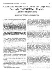
proposed. The PID phase compensation parameters of the auxiliary damping controller were optimized by a genetic algorithm to obtain optimum damping in the entire sub-synchronous frequency band. Finally, the IEEE first benchmark model, modified by the inclusion of the DFIG-based wind farms, is used to demonstrate the performance of the proposed auxiliary damping control to suppress SSR oscillations by time domain simulation analysis with the use of DigSILENT/PowerFactory. 2. Power System Model with DFIG-Based Wind Farm To evaluate the effectiveness of the proposed strategy on auxiliary damping control, the well-known IEEE first benchmark model, modified by the inclusion of DFIG-based wind farms, is used (Figure 1). The system consists of an 892.4 MWA turbogenerator connected to an infinite bus through a radial series-compensated line. The rated voltage is 539 kV, and the frequency is 60 Hz. A DFIG-based wind farm (200 MW from the aggregation of 2 MW units) is connected to bus A via a transformer. Figure 1 shows that G represents the turbogenerators; C, the DFIG-based wind farms; D, the turbine shaft system; and E, the infinite power grid. RL + jXL is the power transmission line impedance, Xc is the captance of the series compensation capacitor, and Xsys is the reactance of the transmission line to the infinite power grid. The complete electrical and mechanical data are given in the Appendix. Figure 1. Schematic of a DFIG-based wind farm connected to the IEEE first benchmark model.
2.1. Turbogenerator Shaft System Model The turbogenerator shaft system consists of six shaft segments, namely, a high-pressure turbine (HP), an intermediate-pressure turbine (IP), a low-pressure turbine (LPA), a low-pressure turbine (LPB), the generator (GEN), and the exciter (EXC). All masses are mechanically connected to one another by elastic shafts. The shaft system motion equation is described as follows:
Energies 2014, 7
3089
dΔω 1 Δ T HP = 2T J 1 dt + D11 Δ ω 1 + D12 (Δ ω 1 − Δ ω 2 ) + k 12 (Δ δ 1 − Δ δ 2 ) dΔω 2 + D 22 Δ ω 2 + D12 (Δ ω 2 − Δ ω 1 ) + D 23 (Δ ω 2 − Δ ω 3 ) Δ T IP = 2T J 2 dt + k 12 (Δ δ 2 − Δ δ 1 ) + k 23 (Δ δ 2 − Δ δ 3 ) dΔω 3 ΔT = 2T J 3 + D 33 Δ ω 3 + D 23 (Δ ω 3 − Δ ω 2 ) + D 34 (Δ ω 3 − Δ ω 4 ) LPA dt + k 23 (Δ δ 3 − Δ δ 2 ) + k 34 (Δ δ 3 − Δ δ 4 ) dΔω 4 Δ T LPB = 2T J 4 + D 44 Δ ω 4 + D 34 (Δ ω 4 − Δ ω 3 ) + D 45 (Δ ω 4 − Δ ω 5 ) dt + k 34 (Δ δ 4 − Δ δ 3 ) + k 45 (Δ δ 4 − Δ δ 5 ) − Δ T = 2T d ω 5 + D Δ ω + D (Δ ω − Δ ω ) + D (Δ ω − Δ ω ) e J5 55 5 45 5 4 56 5 6 dt + k 45 (Δ δ 5 − Δ δ 4 ) + k 56 (Δ δ 5 − Δ δ 6 )
(1)
where δi, ωi, TJi are the angular displacement, angular velocity, and inertia time constant of the i-th mass of the shaft system, Ti is the dynamic torque that affects the i-th mass of the turbogenerators, Te is the electromagnetic torque of the turbogenerator, and ki, i+1 is the rigidity coefficient between the i-th and i+1-th masses. Dii represents the self-damping ratio of the i-th mass, and Di, i+1 is the mutual damping ratio between the i-th and i+1-th masses. The above equation can be simplified as follows:
ΔT = (TJ p 2 + Dp + K )Δδ
(2)
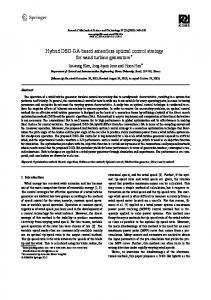
where TJ, D are the inertia time constant and the damping diagonal matrix, respectively, K is the rigidness coefficient tridiagonal matrix, and p is the differential operator. 2.2. DFIG-Based Wind Turbine Model The typical DFIG configuration consists of a wound rotor induction generator, with the stator directly connected to the grid and the rotor interfaced through a back-to-back partial scale power converter, as shown in Figure 2. The back-to-back converter is a bi-directional power converter that consists of two conventional voltage source converters (an RSC and a grid side converter or GSC) and a common dc-bus. Both GSC and RSC contain an internal current controller and an external power controller. The slow power controller provides a reference current to the fast current controller, which further regulates the rotor current to the reference value. The RSC aims to independently control the active power of the generator and the reactive power produced or absorbed from the grid. The GSC aims to keep the dc-link voltage constant, regardless of the magnitude and direction of the rotor power and to guarantee converter operation with unity power factor (zero reactive power). This requirement means that the GSC exchanges only active power with the grid, so the transmission of reactive power from the DFIG to the grid is done only through the stator [18,19].
Energies 2014, 7
3090 Figure 2. Schematic of the DFIG wind turbine.
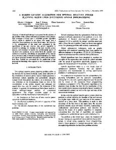
3. Damping Analysis with the Reactive Power Control of Wind Farms To analyze the mechanism of influence of the DFIG-based wind farms on system SSR damping, the system model in Figure 1 is simplified in Figure 3, where E is the quadrature-axis transient electromotive force of turbogenerator G; VA is the voltage of bus A; VB is the infinite bus voltage; δ, γA is the phase angle difference between E, VA, and VB; Pe, Qe are the active/reactive power output of the turbogenerator; Pg, Qg are the active/reactive power output of the DFIG-based wind farms; PL, QL are the active/reactive power flow through the transmission line; and X1, X2 are the reactance parameters. Figure 3. Schematic of the simplified system model.
The output active/reactive power Pe/Qe of the turbogenerator can be expressed as: Pe =
EV A sin(δ − γ A ) X1
(3)
Energies 2014, 7
3091
ΔVA =
X1 ΔQg E cos(θ0 ) − 2VA
(4)
In the following small signal analysis derivation, the variation of the reactive power from DFIG based wind farm is assumed to only led to minor amplitude changes of the bus voltage VA, the quadrature-axis transient electromotive force of turbo-generator E could be regarded as a constant. Thus, the deviation analysis of Equations (3) and (4) can lead to: ΔPe = ΔQ e = −
EV A cos(θ 0 ) E sin(θ 0 ) ( Δ δ − Δγ A ) + ΔV A X1 X1
E cos( θ 0 ) − 2V A EV A sin( θ 0 )( Δδ − Δγ A ) + ΔV A X1 X1
(5) (6)
where θ0 = δ0 −γ A0. The subscript 0 represents an initial value. Considering the minor amplitude changes of the bus voltage VA is assumed to be only caused by the variation of the reactive power from DFIG based wind farm, the increment ΔVA can be obtained as: ΔV A =
X1 ΔQ g E cos(θ 0 ) − 2V A
(7)
Then, according to the active power balance of the transmission line, the next linearization equation can be obtained: V AV B cos( γ A0 ) V sin( γ A0 ) Δγ A + B ΔV A = ΔPe X2 X2
(8)
Substitute Equation (5) into above equation, the next equation can be obtained:
Δγ A = k1Δδ + k 2 ΔV A
(9)
where: k1 =
X 2 E cos(θ 0 ) X 2 E cos(θ 0 ) − X 1V B sin( γ A0 ) k2 = X 1V B cos( γ A0 ) + X 2 E cos(θ 0 ) , X 1V AV B cos( γ A0 ) + X 2V A E cos(θ 0 )
Next, Equations (7) and (9) was substituted into Equation (5), and ΔPe can be rewritten as follows: ΔPe =
EVA cos(θ 0 )(1 − k1 ) EVA k 2 cos(θ 0 ) + E sin(θ 0 ) ΔQg Δδ + X1 2V A − E cos(θ 0 )
(10)
The above equation indicates that the ΔPe has two items. The first item is proportional to the Δδ, which can produce synchronous torque. The second item is related to DFIG reactive power ΔQg, which may produce positive or negative damping effects on the system according to the phase relationship between ΔQg and turbogenerators Δω. To analyze the damping effects of reactive power ΔQg on the system, the transfer function Gωq(s) based on turbogenerator speed ω(t) and the output reactive power Qg(t) of the wind farms (referred to as the reactive-speed transfer function) are derived by using the linearization state equation of DFIG in [20,21]: G ωq ( s ) =
ΔQ g ( s ) Δω ( s )
= K q ( sI − A) −1 B
(11)
Energies 2014, 7
3092
l u uds 0 where K q = − m qs 0 0 0 0 0 0 , A and B can be seen in Appendix. ls ls Also, to analyze the damping effects of active power ΔPg on the system, a transfer function similar to above equation (referred to as the active-speed transfer function) can be derived:
G ωp ( s ) =
ΔPg ( s ) Δω( s )
= K p ( sI − A) −1 B
(12)
l u u where, K p = 0 − m qs 0 0 ds 0 0 0 0 . ls ls Given the sinusoidal microvariation of turbo-generators Δω with amplitude A and frequency ω0 ( Δω = A sin(ω 0t ) ), the microvariation of reactive power ΔQg can be expressed as follows: ΔQ g = A Gωq ( jω 0 ) sin(ω 0 t + ∠Gωq ( jω 0 ))
(13)
To analyze the damping effects of the last item of Equation (10), we define the component of the last item on Δω as reactive power damping ratio Dωq.: Dωq =
EVA k2 cos(θ 0 ) + E sin(θ 0 ) Gωq ( jω0 ) cos(∠Gωq ( jω0 )) 2VA − E cos(θ 0 )
When the phase angle between the range −
π 2
< ∠Gωq ( jω 0 )
0 and Dωq were proportional to
|Gωq(jω)|. Therefore, to enable the reactive power ΔQg of the DFIG-based wind farms to offer positive damping on SSR, the phase angle range of active-speed transfer function Gωq(s) in the subsynchronous frequency band (62.8 rad/s to 314 rad/s) should be satisfied as follows: −
π 2
< ∠ G ωq ( jω )