An Optimization Approach to the Computer Simulation of Composite Materials JAIME HORTA-RANGEL,2 WITOLD BROSTOW,1,2 GONZALO MARTINEZ-BARRERA3 4, AND VICTOR M. CASTAN˜O * 1 Department of Materials Science, University of North Texas, Denton TX 76203-5310, USA 2
Facultad de Ingenieria, Universidad Auto´noma de Queretaro, Queretaro Qro. 76010, Me´xico 3
4
Universidad Auto´noma del Estado de Me´xico Toluca Estado de Me´xico, Me´xico
Centro de Fisica Aplicada y Tecnologia Avanzada, Universidad Nacional Auto´noma de Me´xico, A.P. 1-1010, Queretaro, Qro. 67000, Me´xico
ABSTRACT: A procedure for the optimal modal design of a beam made of a composite material was developed. The two components considered for the composite are a light concrete as the matrix and a polyester fiber as the filler. The fibers inside of the matrix tend to aggregate and to take this into account in the modeling, a subroutine that generates random finite elements corresponding to the fiber clusters was constructed. Three-dimensional simulation using a volumetric model allows to obtain the solutions by means of a coupled modal analysis-optimization procedure, by employing the ANSYS software. The weight of the beam is considered as the objective function. Restrictions are imposed on the first resonant frequency as well as on the design parameters: percentage of fiber polyester, density of the components, and thickness of the beam. The results provide the optimum set of solutions in terms of the parameters that minimize the weight of the beam, while maintaining the first frequency within a specified range of values. KEY WORDS: composite material, optimal design, modal analysis, random fibers, coupled analysis.
INTRODUCTION
D
materials can have unusual properties. For example, carbon-black composites made out of rigid particles embedded in a soft matrix form a type of large fractal cluster. If we try to deform such materials, the distribution of the forces on the rigid and soft particles depends on the topology of the system [1–4]. If the system is indeed fractal, this distribution will not follow classic laws of mechanics. The same idea applies to their vibrating properties. Nowadays, composite materials constitute one of the most important engineering materials. They are obtained by combining different components: concrete, metals, ISORDERED AND RIGID
*Author to whom correspondence should be addressed. E-mail:
[email protected] Figures 3, 4 and 9 appear in color online: http://jrp.sagepub.com
Journal of REINFORCED PLASTICS
AND
COMPOSITES, Vol. 28, No. 6/2009
0731-6844/09/06 0691–9 $10.00/0 DOI: 10.1177/0731684407086966 ! SAGE Publications 2009 Los Angeles, London, New Delhi and Singapore
691
692
J. HORTA-RANGEL ET AL.
polymers, ceramics, etc. These material, are widely used in a large variety of applications [5–8]. Diverse requirements can be imposed on them, such as: specific dynamic response, thermal and corrosion resistance, optical properties, high elastic recovery, wear resistance, and so on. The vast majority of composite materials are largely made up of two components: a basis material or matrix, and the aggregate. The association will depend on the use and the specific imposed requirements. The constitutive characteristics of composite materials depends on all these components. Fiber concentration, for example, is mainly responsible for the strength of the specimen under loads. Also, the random location of the fibers on concrete matrix [7], causes significant variations on Young’s modulus. In the case of resin with ceramic particles, modulus diminishes according to the particle concentration and increases when the size particle size diminishes. The most common analytical model considers a composite material made of thin layers, each one having specific constitutive parameters together with isotropic properties [9] (commonly orthotropic). Some studies consider that the percentage of fibers inside of a layer changes with depth, but maintains the distribution on the layer plane [10]. This is a good approach, taking into account that fibers have a random distribution inside of the body, even though they tend to agglomerate. For that reason, the mentioned procedure does not always agree with the actual experimental behavior of the whole body. In other procedures, dynamic resonance testing can assess physical and mechanical properties of fiber-reinforced composites by evaluating the resonant frequency of vibration [2,11]. Elastic modulus can be calculated by knowing the dimensions of the body, density, and resonance frequency. Correlation between tensile strength and resonance frequencies of structural components can be established experimentally. Relevant physical factors, however, are influenced by the effects of porosity and other microstructural defects that affect density and elastic modulus. In this case, ultrasonic methods are used to determine the properties of the composite materials. However, in some cases where the aggregates are bigger, the signals scatter strongly, making the interpretation of results very difficult. Wave propagation in an anisotropic medium is different than in an isotropic one. The most important differences are the type of mode shapes, the number of mode shapes, and the variation of the velocity with the direction of propagation. Elastic modulus, and Young and Poisson parameters, are determined through propagation velocities of acoustic waves. In the case of heterogenous material, constitutive characteristics associate nine elastic modulus. Finally, thermographic studies allow us to observe voids, clusters and even strange materials inside concrete beams. This explains the complex behavior of these elements [12]. It is well known that the interphase region plays an important role on the overall mechanical properties of polymer matrix fiber composites [13,14]. For example, in the case of a matrix reinforced with plastic fibers, when the ratio fiber/matrix is low (36%) the interfacial fracture energy increases, and for high values (95%), the interfacial fracture energy decreases. Numerical finite element procedures are very important to analyze the behavior of a composite material with complex internal structure, to diagnose the location, configuration, and sensibility requirements when ultrasonic tests are carried out. The use of analytical models helps in reducing the uncertainty of probe tests.
693
An Optimization Approach to the Computer Simulation
The goal of the present work is the simulation of a composite material made of a matrix having elastic modulus E1, !1, reinforced with a second phase with E2, !2, randomly distributed inside of the whole body. A characteristic of this work is the three-dimensional simulation by using a volumetric model. In addition to considering a random distribution of the fibers inside the concrete matrix, this model provides a more realistic behavior of the beam.
SIMULATION PROCEDURE A composite clamped beam with dimensions LGI, GRU, and ALT (length, width, and depth), as shown schematically in Figure 1, is considered. The values of the parameters DENS1, DENS2, PORC, and ALT, must be determined, so the weight of the beam reaches a minimum and its first resonance frequency can be no higher than some specified values. DENS1 is the density of the matrix material; DENS2 is the density of polyester fibers; PORC is the percentage of volume fibers with respect to the whole volume beam; and ALT is the depth of the beam according to some preset values. To generate the random distribution of the fiber clusters, we create a preprocessor subroutine. All elastic parameters are taken into account, as in the concrete matrix, as well as in the fiber clusters. Figure 2 shows the random clusters at the beginning of the optimization cycle. There can be much more than four variables. There are parameters that significantly affect the behavior of the beam, as found in Young’s modulus, density, and Poisson relation. However, in optimization problems, processing time increases with the number of variables. Also, the possibility to find a global minimum of the objective function diminishes when the number of variables increases. For that reason, trying to reduce the Clampled End
GRU
ALT
LGI Figure 1. Beam made of composite material.
Y
Figure 2. Random distribution of fibers inside the composite.
694
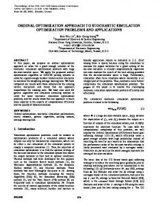
J. HORTA-RANGEL ET AL. 2500000 y= −2E+16x2 + 5E+11x − 465814 Steel Young's modulus (kg/cm2)
2000000
1500000
1000000 Alluminium alloy Glass
500000
Light concrete 0 0.00E+00
Nylon 5.00E–06
1.00E–05
DENSITY (kg-s2/cm4) Figure 3. Relation between modulus E and density ".
number of variables in the optimization model, we made an analysis of the relation between density and Young’s modulus of different materials reported in the literature [15]. The results are shown in Figure 3. So, the equation which relates the module E with the density of material is: EðDENSÞ ¼ $2 % 1016 DENS2 þ 5 % 1011 DENS $ 465 814:
ð1Þ
The Poisson module is maintained at a fixed value of 0.2. However it is important to adjust this value in the last stages of the analysis. OPTIMIZATION PROBLEM The optimization model involves the weight of the beam as the objective function. We can express it in terms of variables and parameters: Weight ¼ ðDENS1 $ ðPORC' ðDENS1 $ DENS2ÞÞÞ % ðLGI' ALT' GRU' 1000Þ:
ð2Þ
Here, Young’s modulus E is in kg/cm2 units, length in cm, and densities are in kg-s2/cm4 The function weight must be minimized under the following conditions: State Variable: First Resonance Frequency: 35 ( ðFREQÞ1 ) 45:
ð3Þ
An Optimization Approach to the Computer Simulation
695
Design variables: 150e-8 ( DENS1 ) 240e-8 50e-8 ( DENS2 ) 780e-8 0:01 ( PORC ) 0:08
ð4Þ
3 ( ALT ) 10
This problem requires minimizing the objective function Z: Z ¼ f ðx1 , x2 , x3 , x4 Þ
ð5Þ
Under the conditions: giðx1 , x2 , x3 , x4 Þ ) ai
bk ) xk ( bk
i ¼ 1, r;
k ¼ 1, 4:
ð6Þ
xk is the design variable and r is the number of restrictions. This is a non-linear optimization problem. There exist different techniques to solve it. We use the SUMT (sequential unconstrained minimization technique), under the Program Ansys [1]. COUPLED MODAL ANALYSIS WITH OPTIMIZATION The discrete model which governs the modal analysis [15] of an undamped body, is as follows: ð½K+ $ !2 ½M+ÞfUg ¼f 0g
ð7Þ
where [K] is the stiffness matrix, [M] is the mass matrix, {U} is the eigenvector, and ! is the circular natural frequency. The beam model has been built by means of volumetric finite elements, having four nodes and 12 degrees of freedom (see Figure 4). The number of finite elements varies on each optimization cycle due to changes of beam depth (ALT). On the initial cycles this number is about 6000 elements. Due to the high number of the degrees of freedom and consequent roots in the characteristic equation, we have used the Guyan method, selecting 10 master degrees of freedom (MDOF). Reducing the processing time in finding mode shapes and resonance frequencies. Figure 5 shows the flow chart of the coupled process modal analysis–Optimization. The process requires the initial values of the design variables. The variables can have any value, including zero. However, it is convenient, for processing time, to propose some values closer to those expected. With these values and all the data, we execute the modal analysis of the beam, finding the first frequency resonance and the weight of the beam. The next step consists of applying the optimization procedure to find the optimal set solution. In the case that the set or sets found are not inside the space of feasible solutions, or they are not the best solutions, we will repeat the entire procedure. We will return to the modal analysis now with our new variable values and repeat the whole cycle until we find the best optimal solution.
696
J. HORTA-RANGEL ET AL. Material 1: Concrete (DENS1, E1, NU1) Material 2: Fibers (DENS2, E2, NU2)
Tetrahedral finit element 6 degrees of freedom each node. Clamped end Ux=Uy=Uz=0 RotX=rotY=rotZ=0
Figure 4. General view and data of the composite beam.
Initial values of design variables DENS1, DENS2, PORC, ALT
Subroutine of generation random elements
Modal analysis -Obtention of natural frequencies-
Optimization Module. Objective Function: Weight
no End
Optimal solution
Figure 5. Flow chart of optimization procedure.
An Optimization Approach to the Computer Simulation
697
We analyzed a beam with the dimensions: LGI ¼ 10 cm and GRU ¼ 10 cm. We maintained all those restrictions to the variables as mentioned above [3,4]. Figures 6–8 show the first three mode shapes of the beam at the beginning of the optimization process. Likewise, Figure 9 shows the variation of objective function–Weight-in whole optimization cycles. The best optimal set was obtained after 50 cycles. DENS1 ¼ 0:21E $ 5 kg-s2 =cm4 ðY ¼ 2:1T=m3 Þ DENS2 ¼ 0:1E $ 5 kg-s2 =cm4 ðY ¼ 1:0T=m3 Þ PORC ¼ 1:78%;
ALT ¼ 5:43 cm
ðFREQÞ1 ¼ 44:1 Hz; WEIGHT ¼ 11:436 kg:
Freq=55.351
Figure 6. First mode shape (units in Hz).
Y Freq=78.228
Figure 7. Second mode shape (units in Hz).
Freq=422.231
Figure 8. Third mode shape (units in Hz).
ð8Þ
698
J. HORTA-RANGEL ET AL. 11.54
Weight: kg
11.52 11.5 11.48 11.46 11.44 11.42 42.5
43
43.5
44
44.5
45
First frequency: Hz Figure 9. Behavior of the objective function.
CONCLUSIONS The modal analysis-optimization procedure developed in this work can be applied to many cases, but is strongly oriented to those materials having more than one component. Due to their heterogeneity, most natural and engineering materials can be considered and analyzed as composite materials [15]. The case solved here shows a typical material used in building construction. Polymers can also be considered by our model [16]. The use of this theory allows us to obtain a better prediction of the behavior of the body under loads. The inclusion in this work of a coupled optimization–modal analysis procedure allows us to obtain an optimal design in terms of the depth of beam, density of the two components involved in the material, as well as on the percentage of fiber. However, we can consider more than two components and involve stress or failure restrictions.
REFERENCES 1. ANSYS, Inc. Software, ver. 6.1, USA. 2. Cumaraswamy Vipulanandan and Hongwei, J. I. A. (1998). Nondestructive Evaluation of Fiber Reinforced Polyester Polymer Concrete, Proceedings of the SEM Spring Conference on Experimental and Applied Mechanics. Houston, TX, pp. 215–216. 3. Shim, V. P. W., Yuan, J. and Lim, C. T. (2000). Dynamic Tensile Response of a Carbon Fiber Reinforced LCP Composite and its Temperature Sensitivity, Proceedings of the Second International Conference on Experimental Mechanics, SPIE, International Society for Optical Engineering. Vol. 4317, Dec. Singapore, pp. 100–105. 4. Muhammad Sahimi (1994). Applications of Percolation Theory, Burgess Science Press, Great Britain, pp. 157–191. 5. Horta, J. M., Hernandez, J. B., Marquez, L., Perez, M. A. and Castan˜o, V. M. (1998). Dynamic Mechanical Properties of a Cement Based Fiber-Reinforced Composite, Journal of Advanced Composite Letters, 7(2): 45–48. 6. Hernandez, J. B., Marquez, Z. A., Horta, A. J., Olivares, M., Alarcon, Ch. P. and Castan˜o V. M. (1998). Effect of the Addition of Cellulose on the Mechanical Performance of Fiber-Reinforced Mortars, Journal Advanced Composite Letters, 7(5). 7. Horta, J., Hernandez, B., Marquez, L., Perez, M. and Castan˜o, V. (1998). Characterization of a Material Composite to use in the Construction Industry, Proceedings of the SEM Spring Conference on Experimental and Applied Mechanics, Houston, TX, pp. 98–100.
An Optimization Approach to the Computer Simulation
699
8. Trtik, P. and Bartos, P. J. M. (1999). The use of Depth Sensing Indentation (DSI) System for Assessment of Characteristics of Bond Glass Fiber-Reinforced Cement Composite, Proceedings of the 24th Conference Our World in Concrete and Structures, Singapore, pp. 415–421. 9. Marx, F. and Ambe, P. (1989). Composite Structures, Swanson Analysis Systems, Inc. Houston, PA. 10. Odom, O. and Rogers, S. (1998). The Mechanical Behavior of Composite Materials with Fiber Volume Gradients, Proceedings of the SEM Spring Conference on Experimental and Applied Mechanics, Houston, TX, pp. 355–358. 11. Summerscales, J. (1990). Non-Destructive Testing of Fiber-Reinforced Plastic Composites, Vol. 2, pp. 151–200, Elsevier Applied Science, London. 12. Nokes, J. P., Hawkins, G. F. and Johnson, E. C. (1998). Thermografic Inspection of Composite Reinforced Concrete Columns, Proceedings of the SEM Spring Conference on Experimental and Applied Mechanics, Houston, TX, pp. 302–304. 13. Winter, R. M. and Houston, J. E. (1998). Interphase Mechanical Properties in an Epoxy-Glass Fiber Composites as Measured by Interfacial Microscopy, Proceedings of the SEM Spring Conference on Experimental and Applied Mechanics, Houston, TX, pp. 355–358. 14. Qing-Qing, N. I., Kurashiki, K. and Iwamoto, M. (2000). A New Approach to Evaluation of Fiber/Matrix Interphase, Proceedings of the Second International Conference on Experimental Mechanics, Vol. 4317, pp. 274–279, SPIE-International Society for Optical Engineering, Nov.–Dec., Singapore. 15. Timoshenko, S. and Gere, J. (1996). Mecanica de Materiales. Ed. Limusa, Mex, pp. 794–795. 16. Blonski, S. (1991). Computer Simulation of Mechanical Behavior of Polymer Liquid Cristals, PhD. Dissertation UNT.