like Hopf [6] or Matsuoka [7] to model these neural activities and generate ..... [24] Hans-Georg Beyer,"Evolutionary algorithms in noisy environments: theoretical ...
An Optimized Gait Generator Based on Fourier Series Towards Fast and Robust Biped Locomotion Involving Arms Swing Nima Shafii, Ali Khorsandian, Abbas Abdolmaleki, Bahram Jozi Mechatronics Research Laboratory (MRL) Department of Computer and Electrical engineering Azad University of Qazvin Qazvin, Iran {shafii ,khorsandian ,abdolmaleki ,jozi}@mrl.ir Abstract - Bipedal locomotion is one of the most challenging problems in control, artificial intelligence, mechanics and other related fields. In this article a model free approach with emphasis on making robot’s walking more stable and faster is presented. In this regard we use Particle Swarm Optimization (PSO) to optimize the signals produced by Truncated Fourier Series (TFS) which control joints’ angels. The role of hands is also considered to smooth walking and to increase its robustness. For the first time a new method will be introduced to improve the speed and robustness of bipedal walking by refining signals and reducing the role of inertia. Simulation results show this approach can make the robot's walking more stable and faster than walking without considering the role of hands and inertia effect.
angular trajectories for controlling bipedal locomotion but it was not implemented on real robot. For the first time Particle Swarm Optimization (PSO) is used to optimize the produced signals by Truncated Fourier Series (TFS) to walk a simulated robot. Our approach is also capable to produce hand angular trajectories with emphasizing the role of hands in smooth and robust walking. In the continuance of the article a new method to refine signals for reducing the role of inertia will be introduced to improve the speed and robustness of the robot and at the end of the article results of this approach will be introduced.
Index Terms - Bipedal Locomotion, Gait generator, Truncated Fourier Series, Arm swing, PSO
We test our method on a simulated humanoid robot. The robot model in this study is NAO robot and the simulation is performed by Rcssserver3D [9] we are using a generic threedimensional simulator which is based on Spark and Open Dynamics Engine (ODE). The simulator environment with robot Model is shown in Fig.1, The robot model has 22 DOF with a height of about 57cm, and a mass of 4.5kg.
I. INTRODUCTION Bipedal walking has become more popular these years, since robots can do their work in a hard and complex environment by means of legged locomotion. But bipedal walking still needs more time to achieve its goal. Various methods have been presented which can be classified into two big groups. One is model-based and another one is model free. In model-based approach first the physical model of the robot is designed, and then a controller will be built for it. "Zero Moment Point" [1]. (ZMP) and "Inverted Pendulum" [2] are two methods of this approach. In model–free approach the sensory information is used for making motions. As the matter of fact, there is not any consideration of physical model in this method and skills are implemented in an easier way. Passive Dynamic Walking (PDW) [3] Central Pattern Generator (CPG) [4] and Ballistic walking [5] are the important methods of model-free approach. In PDW approach, the robot does not have any actuators model and it walks just by utilizing the gravity force. Researchers usually focus on complex mathematical models like Hopf [6] or Matsuoka [7] to model these neural activities and generate rhythmic walk patterns (Gait). In 2007 Truncated Fourier Series Formulation method was used as a gait generator in bipedal locomotion [8]. In mentioned article Truncated Fourier Series (TFS) together with a ZMP stability indicator was used to prove that TFS could generate suitable
II. SIMULATOR AND ROBOT MODEL
III. LEG'S ANGULAR TRAJECTORIES GENERATOR There are six DOFs in each leg; two in the hip, two in the ankle and one at the knee. An additional DOF that exists at each leg's hip for yaw causes the legs to rotate outward and inward. It is found that 6 DOFs (three for each leg) are more important than other DOFs in walking which are DOFs of hip; knee and ankle that move forward-backward on the same plane. In this work, similar to [10] Foot was kept parallel to the ground by using ankle joint in order to avoid collision. Therefore ankle trajectory can be calculated by hip and knee trajectories and ankle DOF parameters are eliminated. In 2007 [8] a much more optimized gate generator was presented. TFS together with a ZMP are used to prove that TFS can generate suitable angular trajectories for controlling bipedal locomotion. It does not require inverse kinematics and Stable gaits with different step lengths and stride frequencies can be readily generated by changing the value of only one parameter in the TFS. According to this approach, the signals are divided in two parts: the upper portion and the lower portion. Each signal has
an offset. C h is offset of hip trajectory and Ck is offset of knee trajectory. From
t1 to t 2 the left leg is considered as
supporting leg and the variation of its knee angle is so minute that can be assumed fixed. This duration of walking is named knee lock phase. In addition, the amount of shift phase of the two leg trajectories signal is as half of the period of each signal so by producing trajectory of one leg the other leg's trajectory can be calculated. The trajectories for both legs are identical in shape but are shifted in time relative to each other by half of the walking period. The TFS for generating each portion of hip and knee trajectories are formulated as below (1).
effect of arm swing during the walking reduces body twisting torque along the vertical axis. Inasmuch as the upper limb moves forward (as the same time)when contra lateral lower limb moves forward ;therefore, the angular momentum of contra lateral upper and lower limbs partially balances each other and reducing the rotational moment between the foot and the ground. In case of straight forward walking, especially on high speed walking, human being must swing arms to absorb yaw moment caused by legs swing. The role of arm swing is very vital on this problem [15], Fig.2. Finally, we can have a robot with faster walking in a stable manner by swing arms.
n
θ h+ = ∑ Ai .sin ( iwht ) + ch , wh = 2π / Th i =1 n
θ h− = ∑ Bi .sin ( iwht ) + ch , wh = 2π / Th
(1)
i =1
n
θk+ = ∑ Ci .sin ( iwk t ) + ck , wk = wh i =1
θ = ck ≥ 0 In these equations, the plus (+) sign represents the upper portion of walking trajectory and the minus (-) shows the lower portion. i = 1 and Ai , Bi , Ci are constant coefficients for generating signals. The h and k index stands for hip and knee respectively. Also Ch , C k are signal offsets and Th is assumed a period of hip trajectory. Considering the fact that all joints in walking motion have equal movement frequency and stride rates is statistically equal, the equation w k = w h = 2 π / T h − k
t1 is the start time of lock phase for knee joint and parameter t2 represents the end time of can be concluded. Parameter
Fig. 2 The role of hand in absorbing yaw moment
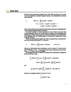
A. Modeling of Arm Swing During human walking, the arms normally swing in a opposite manner to legs, which helps to balance the angular momentum generated in the lower body [13],[11]. Humans swing their arms close to 180º out of phase with their respective legs during walking [16], Fig. 3 shows the trajectory of legs and arm swings and the relation between them in a stable straight walking [11]. It is shown that Trajectory of arms is similar to sinusoidal signal with same frequency of legs.
lock phase and in this duration of time θ k− = c k ≥ 0 .Therefore Truncated Fourier series parameters are c h , c k , A i , B i , C i , t 1 , t 2 And an optimization algorithms must optimize the 8 Dimensions Problem to find the best gate generator in this stage. IV. ARM SWING MAKES HUMAN WALKING EASIER Humans naturally swing their arms when they walk or run. Although arm swing has often been compared with pendulum motion, it is not a purely passive phenomenon. Muscle activity controls arm swing magnitude and timing during human locomotion [11]. As humans change walking speed, their nervous systems adapt muscle activation patterns to modify arm swinging for the appropriate frequency. Humans have neural connections between their upper limbs and lower limbs which coordinate muscle activation patterns during locomotors tasks. Mechanical analysis indicates that arm swing during human locomotion helps to stabilize rotational body motion [12]. Elftman first proposed that arm swing during walking balances torso torques caused by swinging of the lower limbs [13]. This idea has been studied further by others with the same general conclusions [11], [14]. The primary mechanical
Fig. 3 Trajectories of legs and arms
It is found that Speed of walking has strong effect on arm swinging during gait. By increasing gait's speed, the arms may swing higher and faster to reduce the effects of longer, quicker steps by the legs [18]. It can be expected that the utilization of arm swing provides good performance to yaw moment stability, and recovery from stumbling. The effectiveness of this method is confirmed as improvement of accuracy of straight walking in different speeds. As has been shown, the trajectory of arms is
a sinusoidal signal; therefore, to produce proper signal to arms swing, it is enough to obtain proper parameters of following (2).
f (t ) = A sin( warmt ) + b
(2)
In Equation (2), A and ω are assumed as amplitude and frequency parameter of signal respectively and b represents the DC bias of the signal. In addition the amount of shift phase of the two arms trajectories signal is half of the period of each signal so by producing trajectory of one arm the other arm's trajectory can be calculated. Since legs and arms have the same frequency ,ωarms can be considered equal to ωlegs .According to the fact that the angle of arms are also zero at the start of walking , b factor is assumed as 0 .To put it in a nutshell, our arm angular trajectory generator is reduced to (3).
f (t ) = A sin( warmt ), warm = wleg
B. Acceleration root mean square (RMS) "The RMS is a measure of dispersion of the data relative to zero, as opposed to the standard deviation, which is a measure of dispersion relative to the mean. However, as the acceleration signals were transformed to give a mean equal to zero, the RMS is synonymous with the standard deviation. This value was used to provide an indication of the average magnitude of accelerations in each direction during a complete walking trial."[19].
(3)
According to mentioned facts only the proper value of parameter A should be obtained. To reach this aim we consider this parameter together with legs trajectory parameters as an optimization problem. V. INCREASING THE STABILITY AND SPEED Human walking is a complex activity which consists of four main sub-tasks [19]: 1) The initiation and termination of locomotors movements 2) The generation of continuous movement to progress toward destination 3) Maintenance of equilibrium during progression 4) Adaptability to meet any changes in the environment We have already described the second item (the generation of continuous movement to progress toward destination) before. In this part we shall describe the first item (The initiation and termination of locomotors movement), but before introducing our solution, an overview on inertia is needed. A. Inertia Inertia is the resistance of an object to a change in its state of motion. In another word "The vis insita, or innate force of matter is a power of resisting, by which every body, as much as in it lies, endeavors to preserve in its present state, whether it be of rest, or of moving uniformly forward in a straight line.", therefore it's one of the reasons which are considered "the initiation and termination of locomotors movements" as one of sub-tasks in human and humanoid walking. Because of the fact that in these two states (initiation and termination) the robot changes its state from stopping to moving and vice versa. An overview of human walking model To have more stable model and to increase the speed of walking in our robots, we need to study the way of human walking. To understand the role of inertia, the definition of acceleration Root Mean Square (RMS) and harmonic ratio are obtained from [19] and after that we will take a look at some data which is derived from [19].
Fig. 4. Acceleration root mean square diagram
The acceleration in five increasing speeds are illustrated in the above picture (point 1 is lowest walking speed and point 5 is fastest possible walking speed and 2, 3, 4 are in between that increases respectively). Fig. 4, shows that the acceleration increases while walking speed is increases. C. Harmonic Ratio The harmonic ratio initially described by Gage [20] and later modified by Smidt et al. [21] was used to provide an indication of the smoothness and rhythm of acceleration patterns. The harmonic ratio is based on the premise that the unit of measurement from a continuous walking trial is a stride (two steps). A stable, rhythmic gait pattern should therefore consist of acceleration patterns that repeat in multiples of two within any given stride, as these patterns are therefore ‘completed’ before subsequent strides take place. Accelerations patterns that do not repeat in multiples of two are problematic, as they produce out of phase accelerations that are not completed within each stride, and therefore manifest as irregular accelerations during a walking trial. [21].
Fig.5. Amplitude of first 20 harmonics
The above picture shows the amplitude of each harmonic number in first 20 harmonic numbers. The human motion will be smoother if subtraction of two following harmonics number was lower; therefore we can see some first strides don’t have a good stable walking.
D. Increasing speed in start time of walking in TFS As it was noted in Fig. 4, to reach a higher speed we need to increase acceleration. We should also take care of the amplitude in harmonic numbers (strides) for having smoother and more stable walking in our robot. According to Fig. 6, with smaller variation of amplitude walking became more stable, therefore by starting with lower amplitude the variation decreased. According to section 3, if the amplitude of angular trajectory is increased, the gaits (walking steps) get bigger and walking has more acceleration and becomes faster. So by Increasing the walking speed and amplitude form standing to running robot can walk more stable and faster. We implemented a model for the robot to walk from smaller gait with lower amplitude to bigger gait with higher speed and acceleration. In this study a linear equation is used to lead the robot to increase the amplitude of trajectory linearly form zero (stop state) to desired angular trajectories. T is assumed as a parameter to determine how much time is needed for this increment algorithm to reach these desired trajectories. All angular trajectories such as arms and legs will be multiplied by the product of the following equation. Without this approach the amplitude is increased in a flash resulting a non stable walking. K = time / T , time < T K = 1, time >= T
(4)
VI. IMPLEMENTATION Bipedal walking is known as a complicated motion since many factors affect Walking style and stability such as robot's Kinematics and dynamics, collision between feet and the ground. In such a complex motion, relation between Gait trajectory and walking characteristic is nonlinear. In this approach the best parameters to generate angular trajectories for bipedal locomotion must be found. This kind of optimization problem is usually difficult; therefore particle swarm optimization (PSO) seems to be the appropriate solution. A. PSO algorithm The PSO algorithm consists of three steps: generating primitive particle’s positions and velocities, velocity update and position update [22]. These parts will be described in sections 4.1, 4.2 and 4.3 respectively. 1) Initializing particles' positions and velocities: In this regard (5) and (6) are used in which Δt is the constant time increment. Using upper and lower bounds on the design i k
variables values X min and X max , the positions X , and i
velocities Vk , of the initial swarm of particles can be first generated randomly. The swarm size will be denoted by N . The positions and velocities are given in a vector format th
where the superscript and subscript denote the i particle at time k.
X 0i = X min + Rand ( X max − X min )
(5)
V0i =
Xmin + Rand( Xmax − Xmin ) Position = time Δt
(6)
2) Updating Velocities: The fitness function value of a particle is used to determine which particle has the best global value in the current swarm ( Pkg ), and to determine the best position of each particle over time ( P i ). The three values that affect the new search direction, namely, current motion, particle own memory, and swarm influence, are incorporated via a summation approach as shown in (7) with three weight factors, namely, inertia factor, w , self confidence factor, C 1 , and swarm confidence factor, C 2 ,respectively. Q w
[ 0 . 4 ,1 . 4 ]
V ki + 1 N
=
V e lo c ity o f P a r tic le i a t tim e k + 1
[ 1Q ,2 ] ( P i − X ki ) V ki + C 1 R a n d + N Δ t�
(7) � � � � C u rren t M o tio n
P a r tic le M e m o r y In flu e n c e
�� ( P k g − X ki ) C 2 Rand Δ t�
� � � �
[1 .5 , 2 ]
S w a r m In flu e n c e
The inertia weight w controls the amount of the previous velocity from the previous step which should be retained. A larger inertia weight facilitates a global search, while a smaller inertia weight facilitates a local search [24]. A balance can be achieved between global and local exploration to speed up search results using a dynamically adjustable inertia weight formulation. Introducing a nonlinear decreasing inertia weight as a dynamic inertia weight to the original PSO significantly improves its performance through the parameter study of inertia weight [23]. This nonlinear distribution of inertia weight is expressed as follow:
w = winit *U − k Where
(8)
winit is the initial inertia weight value selected in
the range [0, 1] and U is a constant value in the range [1.0001, 1.005], and k is the iteration number. 3) Updating the Position Position update is the final step of each iteration which is done by using the current particle position and its own updated velocity vector shown in (9).
X Ki +1 = X Ki + VKi +1Δt
(9)
VI. PSO IMPLEMENTATION In PSO, the parameters of the problems are coded into a finite length of string as a particle. According to above sections, TFS has 8 parameters to generate legs joints angular trajectories and 2 parameters are assumed to swing arms and increase the speed of walking. Therefore there is a 10dimension search space for the PSO to find the optimum solution. Fitness function has a critical role in PSO that is used to judge whether a solution represented by a particle is good or bad. Angular trajectory produced by each particle is used by simulated robot for walking. To use angular trajectory, all
individual robot's joints attempt to drive towards their target angles using proportional derivative (PD) controllers. To equip the robot with a fast walking skill, a fitness function based on robot's straight movement with limited action time is considered. First the robot is initialized in x=y=0 (0, 0) to walk for 15 seconds then fitness function is calculated whenever that robot falls or time duration for walking is over. Fitness function formulation is expressed as follow. If ( ( Current Time >= time duration for walking) or (robot is fallen) ) Fitness: =10*x; End if Due to the fact that there is noise in simulated robot's actuators and sensors, walking training task in this approach can be viewed as an optimization problem in a noisy and nondeterministic environment. Resampling is one of the techniques to improve the performance of evolutionary algorithms (EAs) in noisy environment [24]. In Resembling, the individual set of parameters (particle) yi , the fitness F ( yi )
Fig. 6. PSO convergence for previous TFS
However the previous model of TFS could walk the robot, after 3000 trails and 5 hours from starting PSO in this machine with same specifications, new approach presented in this paper could teach the robot to walk 10.5 m in 15 s. Average and best fitness are shown in Fig.7.
is measured m times and averaged yielding fitness. According to (10) the noise strength of F is reduced by a factor m . F ( yi ) =
σ 1 m F ( yi ), y ( i) = const. ⇒σe = Var ⎡F ( yi ) ⎤ = e (10) ∑ ⎣ ⎦ m k=1 m
Since particles may not be satisfied in constraints during updating position procedure, constraint handling is a vital step in PSO algorithm. We considered various values for each parameter of the algorithm and tried all possible combinations. Finally we chose the best combination of the parameters regarding the dynamic inertia weight and test results that C 1 and C 2 are assumed as 1, 1.5,
winit as 0.8, U as 1.0002 and Δt as 1,
respectively. We have also implied a swarm consisted of 100 particles (N = 100) and maximum iteration of 10 and Resampling factor m is assumed as 3.
Fig.7. PSO convergence for new approach and TFS model
After 4 hours of learning, Robot learned to walk with average body speed of 0.7 m/s. The learned trajectories of left hip and knee from the time robot started to walk are shown in Fig. 8, it is shown that it took 1.5 seconds for robot to increase its speed using increasing speed and increasing amplitude technique (section V). The learned trajectory of left arm (produced in section IV) is also shown in fig. 9.
VII. RESULT To compare the presented method with Basic TFS method, both of them were tested by the same system with the same specification. We also optimized both methods by utilizing PSO with equal specifications and same fitness. Using basic TFS with 8 parameters and running PSO algorithm on a Pentium IV 3 GHz Core 2 Duo machine with 2 GB of physical memory, 3000 trials were performed in 4 hours. Finally the robot could walk 8.6m in 15s with average body speed of 0.57m/s and period of 0.41s for each step. Fig. 6 shows the average and best fitness values during these 10 generations. Fig.8. Left Hip and Knee trajectories
Fig. 9 Left Arm trajectory
CONCLUSION In this paper, we are able to increase the speed and stability of the robots walking compare to previously presented TFS model by using the technique introduced in section 5 and adding arm swing. Considering complexity of walking behavior, it is the first time that this model has been implemented on simulated robot by using PSO on the basic of efficiency of robot walking. According to the fact that this approach is model free based on robot learning, It is capable of being used on all kinds of humanoid robots with different specification. We also improved the robot's control in future based on the learned trajectory by using more complicated controller such as BELBIC [25] instead of PD as a simple controller. REFERENCES [1]
[2]
[3] [4] [5] [6]
[7] [8]
[9] [10]
[11] [12] [13]
M. Vukobratovic,B. Borovac, and D. Surdilovic. “Zero-moment point proper interpretation and new applications”. In Proceedings of the 2nd IEEE-RAS International Conference on Humanoid Robots, Humanoids 2001, pp. 237–244 [Waseda University, Tokyo, Japan, 2001]. S. Kajita, F. Kanehiro, K. Kaneko, K. Yokoi, H. Hirukawa "The 3D linear inverted pendulum mode A simple modeling for a biped walking pattern generation" In Proceedings of the 2001 IEEE/RSJ International Conference on Intelligent Robots and Systems, pp. 239–246, 2001. T. McGeer “Passive dynamic walking.” International Journal of Robotics Research, Vol. 9(2), pp. 62-82, 1990. C. Pinto, M. Golubitsky "Central Pattern Generator for Bipedal locomption" J. Math. Biol. ,Vol. 53, pp. 474–489, 2006, DOI 10.1007/s00285-006-0021-2 S. Mochon and T.A. McMahon “Ballistic walking”,J. Biomech., Vol. 13, pp. 49-57,1980. J. Buchli, F. Iida, A.J. Ijspeert,"Finding Resonance: Adaptive Frequency scillators for Dynamic Legged Locomotion", Proceedings of the 2006 IEEE/RSJ International Conference on Intelligent Robots and Systems, PP. 3903-3910, 2006, Doi: 1-4244-0259-X/06 K. Matsuoka. “Sustained oscillations generated by mutually inhibiting neurons with adaptation.” Biol. Cybern.. Vol. 52, pp. 367-376, 1985. L. Yang, C.M. Chew, T. Zielinska, A.N. Poo, “A Uniform Bipedal Gait Generator with Offline Optimization and Online Adjustable Parameters”, Robotica 2007, Cambridge University Press, Vol. 25, PP. 549-565, 2007, doi 10.1017/S026357470700344X. J. Boedecker, “Humanoid Robot Simulation and Walking Behaviour Development in the Spark Simulator Framework,” Artificial Intelligence Research University of Koblenz, April 2005. S. Kagami, M., Mochimaru, Y. Ehara, N. Miyata, K. Nishiwak, T. Kanade, , Inoue, H.: “Measurement and comparison of humanoid H7 walking with human being,” Robotics and Autonomous Sys, vol. 48, pp. 177—187, 2003. R. N. Hinrichs "Whole body movement: coordination of arms and legs in walking and running", In J. M. Winters and S. L. Y. Woo. New York: Springer-Verlag, pp. 694—705, 1990. E. P. Zehr and J. Duysens "Regulation of arm and leg movement during human locomotion." J. Neuroscientist, Vol. 10, pp.347--361, 2004. H. Elftman, "The function of the arms in walking" Hum. Biol., Vol 11, pp. 529--535, 1939.
[14] Y. Li, W. Wang, R. H. Crompton, and M. M. Gunther "Free vertical moments and transverse forces in human walking and their role in relation to arm-swing", J. Exp. Biol., Vol. 204, PP. 47--58, 2001. [15] K. Osaku, H. Minakata and S. Tadakuma "A Study of CPG Based Walking Utilizing Swing of Arms" AMC’06-Istanbul, Turkey. [16] S. H. Collins, M. Wisse, A. Ruina, "A 3-D passive dynamic walking robot with two legs and knees" Int. J. Robot. Res., Vol. 20, pp. 607-615, 2001. [17] T. Wannier, C. Bastiaanse, G. Colombo, and V. Dietz "Arm to leg coordination in humans during walking, creeping and swimming activities" Exp. Brain Res. , Vol. 141, pp. 375--379, 2001. [18] M.P. Murray, S.B. Sepic, E.J. Barnard, "Patterns of sagittal rotation of the upper limbs in walking" Physical Therapy , Vol. 47, pp. 272–284, 1967. [19] H, Menz, S.R. Lord, R.C. Fitzpatrick "Acceleration patterns of the head and pelvis when walking on level and irregular surfaces", 2002. [20] H. Gage "Accelerographic Analysis of Human Gait" Washington DC: American Society for Mechanical Engineers, 1964. [21] Smidt GL, Arora JS, Johnston RC. "Accelerographic analysis of several types of walking", Am. J. Phys. Med., Vol. 50, pp. 285—300, 1971. [22] X.Chen and Y.Li,”A Modified PSO Structure Resulting in High Exploration Ability With Convergence Guaranteed”,IEEE Transactions on System, Man and Cybernetics: Part B,Vol.37, No.5, pp.12711289,2007. [23] B. Jiao, Z. Lian, X. Gu "A dynamic inertia weight particle swarm optimization algorithm " j Chaos, Solitons and Fractals, Vol. 37, pp. 698–705, 2008. [24] Hans-Georg Beyer,"Evolutionary algorithms in noisy environments: theoretical issues and guidelines for practice", Comput. Methods Appl. Mech. Eng., Vol. 186, pp. 239–267, 2000. [25] C. Lucas, D. Shahmirzadi, N. Sheikholeslami "Intoduction BELBIC: Brain Emotional Learning Based Intelligent Learning Controller" Intelligent Automation and Soft Computing, Vol. 10, No. 1, pp. 11-22, 2004.