Review October 2011 Vol.56 No.28-29: 30723078 doi: 10.1007/s11434-011-4671-0
Optoelectronics
SPECIAL TOPICS:
An overview of resistive random access memory devices LI YingTao1,2, LONG ShiBing2, LIU Qi2, LÜ HangBing2, LIU Su1 & LIU Ming2* 1
School of Physical Science and Technology, Lanzhou University, Lanzhou 730000, China; Laboratory of Nano-Fabrication and Novel Device Integration, Institute of Microelectronics, Chinese Academy of Sciences, Beijing 100029, China 2
Received January 17, 2011; accepted July 13, 2011
With recent progress in material science, resistive random access memory (RRAM) devices have attracted interest for nonvolatile, low-power, nondestructive readout, and high-density memories. Relevant performance parameters of RRAM devices include operating voltage, operation speed, resistance ratio, endurance, retention time, device yield, and multilevel storage. Numerous resistive-switching mechanisms, such as conductive filament, space-charge-limited conduction, trap charging and discharging, Schottky Emission, and Pool-Frenkel emission, have been proposed to explain the resistive switching of RRAM devices. In addition to a discussion of these mechanisms, the effects of electrode materials, doped oxide materials, and different configuration devices on the resistive-switching characteristics in nonvolatile memory applications, are reviewed. Finally, suggestions for future research, as well as the challenges awaiting RRAM devices, are given. resistive random access memory, resistive switching, performance parameters Citation:
Li Y T, Long S B, Liu Q, et al. An overview of resistive random access memory devices. Chinese Sci Bull, 2011, 56: 30723078, doi: 10.1007/ s11434-011-4671-0
A random access memory (RAM) can be either volatile or nonvolatile. A volatile memory loses stored data when power is removed, which is the case for dynamic random access memory (DRAM) and static random access memory (SRAM). A nonvolatile memory does not lose its stored data when power is removed. Memory devices typically combine advantages and disadvantages. For example, DRAMs have high capacity and high density, but are volatile and must be refreshed every few milliseconds, raising power consumption. SRAMs are fast, but are volatile and have large memory cells, reducing capacity. Flash memory, which is currently very popular, has very high capacity and is nonvolatile, but is relatively slow [1–3]. Because no current memory technology satisfies all requirements, research work is constantly seeking new technologies that compensate for weaknesses of any particular type. An ideal memory would have high capacity, fast response, a long retention time, and low power consumption, as well as being nonvolatile and scaling better than current technologies. *Corresponding author (email:
[email protected]) © The Author(s) 2011. This article is published with open access at Springerlink.com
In recent years, emerging nonvolatile memories, such as ferroelectric random access memory (FRAM), magnetic random access memory (MRAM), phase-change random access memory (PRAM), and resistive random accessmemory (RRAM) [4–25], have been enthusiastically studied. Among these candidates, RRAM, which exhibits resistive switching between a high resistance state and a low resistance state, has overwhelming advantages in easy fabrication, simple structure, excellent scalability, fast switching, high integration density, and good compatibility with the current complementary metal oxide semiconductor (CMOS) technology [6–10]. Consequently, more attention is being focused on these devices. The resistive-switching characteristics of different materials, resistive-switching mechanisms, and appropriate ways to improve the resistive-switching characteristics for future nonvolatile memory applications, have been investigated [11–36]. However, a comprehensive review of RRAM devices is needed. This paper presents such a review. It begins with the basic working principle of the device and moves on to the main performance parameters and the resistivecsb.scichina.com
www.springer.com/scp
Li Y T, et al.
Chinese Sci Bull
switching mechanisms, followed by ways to improve the resistive-switching characteristics and an outlook for RRAM applications.
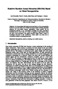
1 Basic working principle A resistive-switching memory cell in an RRAM is generally composed of an insulating or resistive material I sandwiched between two electron-conductive electrodes M to form metal-insulator-metal (MIM) structure. By applying an appropriate voltage, the MIM cell can be switched between a high-resistance state (HRS) and a low-resistance state (LRS). These two states can represent the logic values 1 and 0, respectively. Depending on voltage polarity, the resistive-switching behavior of an RRAM device is classified as unipolar or bipolar. For unipolar switching, resistive switching is induced by a voltage of the same polarity but a different magnitude, as shown in Figure 1(a). For bipolar switching, one polarity is used to switch from HRS to LRS, and the opposite polarity is used to switch back into HRS, as shown in Figure 1(b). A third resistive-switching behavior, shown in Figure 1(c), is nonpolar switching, in which switching from LRS to HRS (the reset process) and from HRS to LRS (the set process) is done with either positive or negative voltage [21]. Regardless of the type of switching, the setting current is usually limited to avoid a hard breakdown of the device [20,21].
2 Main performance parameters The performance parameters of RRAM provide a framework to discuss its advantages and disadvantages. Important performance parameters of RRAM include operating voltage, operating speed, resistance ratio, endurance, retention time, device yield, and even multilevel storage.
October (2011) Vol.56 No.28-29
2.1
3073
Operating voltage
It is well known that a high operating voltage is a fatal flaw in practical application. This is because a high operating voltage means high power consumption. In addition, reliability can be a problem with a high operating voltage. To gain advantage over Flash memory, which does suffer from high operating voltages, both the programming and erasing voltages for RRAM devices should be only a few volts. 2.2
Operating speed
Operating speed is defined as the shortest time for programming or erasing a device cell. Lee et al. [22] reported on the bipolar resistive switching characteristics of a TiN/TiOx/HfOx/TiN RRAM device. The switching speed of this device is as fast as 5 ns, the fastest speed yet reported. At the present time, the best operating speed of RRAM devices is between 5 and 100 ns. 2.3 Resistance ratio Resistance ratio, the ratio of the resistance at HRS to the resistance at LRS, plays an important role in RRAM applications because it directly influences the accuracies of programming and erasing. In general, a resistance ratio greater than 10 is required to distinguish the two resistance states in circuit design [23]. In some RRAM devices, the resistance ratio can be as high as six or seven orders of magnitude [21]. Such a huge resistance ratio suggests the possibility of achieving high-density memory by means of multibit or multilevel storage [21,22]. 2.4 Endurance An RRAM device can be switched between HRS and LRS frequently, but each operation can introduce permanent damage, normally referred to as degradation. Endurance, also called electric fatigue, is the number of set/reset cycles that can be endured before HRS and LRS are no longer distinguishable. To gain an advantage over Flash memory, which shows a maximum number of write cycles between 103 and 107, depending on the type, RRAM should provide at least the same endurance, preferably a better one [23]. 2.5 Retention time Retention time, the length of time a memory cell will stay in one state after programming or erasing, indicates the intrinsic ability of a memory cell to retain its content. Most commercially available products are guaranteed to retain information for at least 10 years, either with the power on or off. 2.6 Multilevel storage
Figure 1 Resistive-switching behaviors of RRAM devices. (a) Unipolar switching; (b) bipolar switching; (c) nonpolar switching.
Multilevel storage refers to the ability of a memory cell to
3074
Li Y T, et al.
Chinese Sci Bull
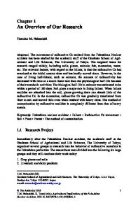
exhibit reproducible resistive switching between multiple resistance states and, consequently, to store multiple values. Multilevel storage can enhance storage density, but requires a large enough resistance ratio between each state to enable an external circuit to distinguish between states. Multilevel storage can be achieved by controlling either compliance current (Icomp) or operating voltage [22,24–26]. In our previous work [5], a WO3-based RRAM device with Cu/WO3/Pt structure was demonstrated to have multilevel storage capability. During the set process, by using different compliance currents, at least four resistance states can be addressed, with each state corresponding to a level of memory. The nonvolatility of the multiple levels is proved by a data retention test at room temperature; the result shows that each resistance state remains stable over 104 seconds and is predicted to have a lifetime of 10 years, as shown in Figure 2. 2.7 Device yield Nonstoichiometric oxide devices generally have a fatal flaw of low device yield due to the uncontrollability of the oxygen concentration. To satisfactorily solve the problem of low device yield for nonstoichiometric oxides, Wu et al. [14] utilized stoichiometric ZrO2 instead of nonstoichiometric ZrO2 for nonvolatile RRAM devices. In addition to this, other methods have been proposed to improve device yield, such as using a suitable electrode material [4], utilizing doped metal oxide [17], and intentionally introducing metal nanocrystals in oxide [28].
3 Resistive-switching mechanisms The underlying mechanisms of resistive-switching in
Figure 2 Retention characteristics of various resistance states of the Cu/WO3/Pt memory device at room temperature: All resistances were measured at a 100 mV reading voltage. Level 1 represents HRS resistance, and levels 2, 3, and 4 represent LRS resistances controlled by Icomp values of 0.1, 1, and 5 mA, respectively. The result predicts a 10 year lifetime for each state. Stability of all four states suggests multilevel feasibility.
October (2011) Vol.56 No.28-29
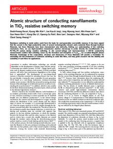
RRAM devices are surprisingly divergent and not yet clearly understood. It has been reported that certain I-V relationships can be used to identify the underlying resistive-switching mechanisms [27–33], which can be mainly divided into: formation and rupture of conductive filaments, space-charge-limited conduction, trap charging and discharging, Schottky Emission, and Pool-Frenkel emission. 3.1 Formation and rupture of conductive filaments The possible mechanism of the formation and rupture of conductive filament can be divided into two main categories: one is the thermochemical effect and the other is the electrochemical effect. With the thermochemical effect, formation and rupture of conductive filaments is based on the Joule heating effect with external electron injection and spontaneous reaction between the metal electrode and oxide films, in which the filaments are composed of defects, such as oxygen vacancies or electrode metal ions, transported into the oxide film [16]. A sketch of the formation and rupture of conductive filaments based on the thermochemical effect is shown in Figure 3 [8]. During the set process, the defects in the oxide film trap electrons randomly under the electric field, and thereby the current paths are formed (Figure 3(a)), leading to resistive switching from HRS to LRS. When a reset voltage is applied, a larger current flows through the oxide film resulting in much heat. Consequently, almost all filaments are ruptured via current joule heating (Figure 3(b)–(d)), and the resistance of the device becomes HRS again. With the electrochemical effect, the formation of conductive filaments is due to redox reactions in solid state electrolytes [29,30,36]. A thin solid electrolyte layer is sandwiched between an oxidizable anode (Ag or Cu) and an inert cathode (Pt or W). The formation of conductive filaments in this case involves the following steps: (i) When a positive voltage is applied on the oxidizable anode, an electrochemical reaction occurs in the anode, which oxidizes the anode metal atoms to metal ions; (ii) the highly mobile
Figure 3 The formation and rupture of conductive filaments based on the thermochemical effect [8]. Formation process (a) and rupture process (b) – (d).
Li Y T, et al.
Chinese Sci Bull
3075
October (2011) Vol.56 No.28-29
cations drift in the ion conductive layer under the electrical field; and (iii) the metal ions are deoxidized back to metal atoms at the inert cathode. As this process continues, metallic filaments are established between the two electrodes and the device switches to LRS. By changing the polarity of the bias voltage, an electrochemical dissolution of the conductive bridges takes place, resetting the device into HRS. Figure 4 shows a sketch of the formation and rupture of Ag conductive filaments based on the electrochemical effect [31]. Whether it is a thermochemical or an electrochemical effect, the most prominent feature in the filament model is a linear relationship between current and voltage, similar to the ohmic characteristic.
the I-V characteristics exhibit ohmic conduction (I∝V). Once the voltage exceeds the trap–filled limit voltage, the curve of I-V fits a child’s square law (I∝V2).
3.2
Schottky emission is usually considered to be thermionic emission of electrons over a reduced work-function barrier resulting from the combined effects of image potential and applied electric field. With Schottky emission, the equation for the current density is q qE 4π B i , (1) J =A*T 2 exp T * where A is Richardson’s constant, which has a theoretical value of 4πqmn* k 2 h3 , mn is the electron mass, k is Boltzmann’s constant, and h is Planck’s constant. The absolute temperature is denoted by T, the electric field by E, the barrier height by b , and the dielectric constant of the film byi. From eq. (1), it is clear that the Schottky emission mechanism can be confirmed by the curve of E1/2∝lnJ.
Space-charge-limited conduction
The second most important mechanism is space-chargelimited conduction (SCLC), which is controlled by defects. The typical I-V characteristic of trap-controlled SCLC generally consists of two different regions, as shown in Figure 5, as reported by Lin et al. [33]. In the low voltage region,
3.3
For trap charging and discharging mechanism, the most obvious characteristics appear in two behaviors, the clear negative differential resistance (NDR) behavior, and a behavior similar to the SV model proposed by Simmons and Verderber [34], in which an N-shaped I–V characteristic is generally obtained in positive voltage [27,35]. 3.4
Schottky emission
Pool-Frenkel emission
Pool-Frenkel emission is controlled by trapped electrons as with the SCLC and trap charging and discharging mechanisms. It is due to field-enhanced thermal excitation of trapped electrons into the conduction band. The I-V characteristic for the Pool-Frenkel effect, which is quite different, can be written as q qE π B i , (2) J ~ Eexp kT from which it follows that the current is very dependent on the electric field and the I-V curve is indicated by the linear fitting to ln(I/V) ∝V1/2.
3.6
Figure 5 The SCLC I-V characteristics of the Ti/ZrO2/Pt device in a double-logarithmic plot (a) positive voltage, and (b) negative voltage region [33].
3.5
Figure 4 The formation and rupture of Ag-conductive filaments based on the electrochemical effect.
Trap charging and discharging
Summary
From the discussions above, it can be concluded that the resistive-switching mechanisms of RRAM devices can be distinguished through the I-V correlation. Work has confirmed that resistive switching generally involves, rather than one mechanism, a combination of several different
3076
Li Y T, et al.
Chinese Sci Bull
mechanisms [33]. Figure 6 shows an example of a combination of mechanisms in our fabricated Cu/WO3/Pt RRAM device [5]. From the linear fittings to the current-voltage curves for both LRS and HRS, it can be seen that the conductive mechanism of LRS is ohmic (filament model) because the slopes in both positive bias and negative bias are very close to one. In contrast, the HRS conductive mechanism is dominated by SCLC. Similar combined mechanisms in an RRAM device are reported in other work [33].
4 Improving resistive switching in RRAM device 4.1 Electrode materials The dependence of resistive switching on both top and bottom electrode materials has recently been reported [4,15, 37]. For some RRAM devices, different electrode materials seem to cause different resistive-switching behaviors, which might depend on the barrier height at the electrode/resistive switching-layer interface. Because the work functions of different electrodes can vary considerably, the type of contact between an electrode and a resistive-switching layer can be determined by Ohmic or Schottky contact. For Ohmic contact, the voltage drop at an electrode/resistive-switching layer interface can be negligible, and the effective electric field inside the resistive-switching film is high enough to induce resistive switching [12,13]. For Schottky contact, if a low Schottky barrier is formed, the voltage drop at an electrode/resistive switching layer interface is small but not negligible [12]. On the other hand, if the Schottky barrier height is quite large, the voltage drop at an electrode/ resistive-switching layer interface is appreciable and the effective electric field inside the resistive-switching film is insufficient to induce resistive switching [13]. For most RRAM devices, before stable resistive switching can be observed a forming voltage much higher than the
Figure 6 Fitting current-voltage curves for both LRS and HRS of the Cu/WO3/Pt RRAM device (a) positive bias and (b) negative bias region. The plot shows that the slopes of LRS in both positive bias and negative bias are very close to one, demonstrating that the conductive mechanism is filament conduction. The HRS in the plot demonstrates that the conductive mechanism is SCLC.
October (2011) Vol.56 No.28-29
normal operating voltage is generally required at the first time of switching from HRS to LRS. Such a high forming voltage blocks the memory behavior. In recent work, we have studied the use of different electrodes to solve the problem of the need for a forming process. Figure 7 shows an example of adopting doped ZrO2 with the same Au top electrode but different bottom electrodes (Au, Pt, Al) to avoid a forming process. Using Au and Pt in the bottom electrodes, the fabricated devices need a forming process (Figure 7(a) and (b)). For the device with Al as the bottom electrode, no forming process is needed (Figure 7(c)). This result may be attributed to the strong deoxidizing capacity of Al. During the set process, some reactions might occur between the Al electrode and O2− ions from ZrO2, leading to much more mobile carriers such as oxygen vacancies in the ZrO2 film. Consequently, the conductive filament can be formed easily with Al as the bottom electrode and the forming process is avoided. On the other hand, we investigated the effect of different top electrodes on the resistive-switching characteristics of WO3-based RRAM devices [4]. Compared with the Al/WO3/Pt and Cr/WO3/Pt devices, the Cu/WO3/Pt device has much better resistive-switching characteristics, such as good reproducibility, low power consumption, multilevel storage, and good data retention [4, 5]. The excellent resistive-switching characteristics of the Cu/WO3/Pt device can be attributed to the electrochemical reactions and migration of the electrochemically active metal Cu in WO3 film [4]. 4.2 Doped oxides In recent years, doped oxides have been investigated in efforts to improve resistive-switching in RRAM applications. It has been reported that doped oxides show better device yield [17]. In addition, compared with non-doped oxides, doped oxides have excellent memory characteristics such as satisfactory switching endurance cycles, potential multilevel storage, long data retention times, and fast switching [4,17,28].
Figure 7 I-V curves of doped ZrO2-based RRAM devices with the same Au top electrode but different bottom electrodes: A forming process is needed with Au (a) and Pt (b) as the bottom electrodes. No initial forming process is needed with Al (c) as the bottom electrode.
Li Y T, et al.
Chinese Sci Bull
October (2011) Vol.56 No.28-29
3077
To further confirm the role of metal doping in resistive switching, Guan et al. [28] intentionally fabricated a device with Au nanocrystals embedded in ZrO2 film. Compared with a sample without Au nanocrystals, the Au nanocrystal device shows better resistive-switching characteristics [28]. This is because the Au nanocrystals act as electron traps and make the trap concentrations more uniform [28]. 4.3 Effect of structure To investigate the effect of device structure on the resistive-switching characteristics of RRAM devices, two different RRAM devices, one with a crossbar structure and one with a via-hole structure, were fabricated by Yu et al. [38]. They investigated the effect of structure on resistive switching of TiOx-based RRAM devices. Their results show that the resistance ratio and the switching voltages of the via-hole structure had little variation, whereas deviation was evident in the crossbar structure with smaller cell-size [38]. These results can be attributed to the elimination of possible sidewall and corner effects in the via-hole structure [38]. To obtain further improvement, Lee et al. [22] added an additional thin Ti layer as a reactive buffer layer between the HfO2 resistive-switching layer and the top electrode. Excellent characteristics were demonstrated in the buffer layer heterostructure memory device, such as low set/reset voltages, low current, high resistance ratio, fast switching, and long data retention. All these results indicate that the Ti buffer layer is important in improving resistive-switching. A buffer layer of oxygen ion conductors was used; the improvement can be attributed to the ability of Ti to absorb oxygen atoms [22]. Our recent work investigated ZrO2-based RRAM devices. We fabricated Cu/ZrO2/Pt and Cu/TiOx-ZrO2/Pt structured devices and investigated their characteristics. With an embedded thin TiOx buffer layer (~3 nm) between the ZrO2 and Cu top electrodes, the Cu/TiOx-ZrO2/Pt device exhibited much better characteristics than did the Cu/ZrO2/Pt device. In particular, the set voltage (Vset) showed a decrease compared with that in the ZrO2-based RRAM device without the TiOx layer, as shown in Figure 8. The improvements in the Cu/TiOx-ZrO2/Pt device might result from the modulation of the barrier height at the electrode/oxide interfaces. Kinoshita and Tsunoda et al. [39] fabricated a 1T1R (one-transistor-one-resistance) configuration device, in which a cell transistor was used as a current limiter. In comparing the 1R and 1T1R devices, the resistive-switching parameters in the 1T1R configuration showed better uniformity. It was also found that the reset current (Ireset) of the device with the 1R configuration alone was larger than that of the 1T1R configuration. For the 1R configuration, Ireset was saturated to greater than 2 mA, even for Icomp < 1 mA, while for the 1T1R configuration Ireset was lower than 1 mA for all the measured range [39].
Figure 8 Distributions of Vset and Vreset for the Cu/ZrO2/Pt and Cu/TiOx-ZrO2/Pt device cells: Z and TZ represent the Cu/ZrO2/Pt and Cu/TiOx-ZrO2/Pt devices, respectively.
5
Summary and prospects
A basic overview of RRAM devices is given, beginning with a brief review of memory devices. The basic working principle, main performance parameters, and resistiveswitching mechanisms, as well as some important factors in improving the resistive-switching characteristics of RRAM devices, are discussed. The difficulties and challenges faced involve understanding the resistive-switching mechanisms and determining how to improve the characteristics: higher resistance ratios, lower operating currents and voltages, lower distributions of Vset, Vreset, RLRS, and RHRS, and better device yields. Although there has been some success, much important work is still underway and more is needed. A class of materials with overwhelming advantages in composition control and compatibility with conventional semiconductor processes, particularly in endurance and retention in practical application, is needed. More attention should be focused on new techniques to achieve faster programming/erasing, higher scalability, lower power consumption, multilevel storage, and lower costs. In particular, work is needed in choosing suitable electrodes, utilizing either nanocrystals or metal ions embedded in an insulating layer, and fabricating devices based on a buffer-layer structure, via-hole structure, and 1T1R configurations. A full understanding of universal switching mechanisms is not yet available. Understanding in detail the switching mechanisms responsible for resistive switching is an urgent need. New technologies and late-model-structured RRAM devices are still in the research stage; many more resistive-switching characteristics need to be demonstrated. With continuing work, we are convinced that resistive-switching RRAM devices will constitute a breakthrough technology and achieve success in future nonvolatile memory applications.
1 2
Kahng K, Sze S M. A floating gate and its application to memory devices. IEEE Trans Electr Dev, 1967, 14: 629 Masuoka F, Asano M, Iwahashi H, et al. A new flash E2PROM cell using triple polysilicon technology. IEDM Tech Dig, 1984, 464–467
3078 3 4
5
6
7
8
9
10 11
12
13 14 15
16
17
18 19
20
21
Li Y T, et al.
Chinese Sci Bull
Chen A, Haddad S, Wu Y C, et al. Non-volatile resistive switching for advanced memory applications. IEDM Tech Dig, 2005, 746–749 Li Y T, Long S B, Lv H B, et al. Investigation of resistive switching behaviors in WO3-based RRAM devices. Chinese Phys B, 2011, 20: 017305 Li Y T, Long S B, Liu Q, et al. Nonvolatile multilevel memory effect in Cu/WO3/Pt device structures. Phys Status Solidi RRL, 2010, 4: 124–126 Zhuang W W, Pan W, Ulrich B D, et al. Novell colossal magnetoresistive thin film nonvolatile resistance random access memory (RRAM). IEDM Tech Dig, 2002, 193–196 Liu C Y, Wu P H, Wang A, et al. Bistable resistive switching of a sputter-deposited Cr-doped SrZrO3 memory film. IEEE Electron Device Lett, 2005, 26: 351–353 Lin C C, Tu B C, Lin C C, et al. Resistive switching mechanisms of V-doped SrZrO3 memory films. IEEE Electron Device Lett, 2006, 27: 725–727 Fujii T, Kawasaki M, Sawa A, et al. Hysteretic current–voltage characteristics and resistance switching at an epitaxial oxide Schottky junction SrRuO3/SrTi0.99Nb0.01O3. Appl Phys Lett, 2004, 86: 012107 Cho B O, Yasue T, Yoon H, et al. Thermally robust multi-layer non-volatile polymer resistive memory. IEDM Tech Dig, 2006, 1–4 Lai Y S, Tu C H, Kwong D L, et al. Charge-transport characteristics in bistable resistive poly (N-vinylcarbazole) films. IEEE Electron Device Lett, 2006, 27: 451–453 Seo S, Lee M J, Kim D C, et al. Electrode dependence of resistance switching in polycrystalline NiO films. Appl Phys Lett, 2005, 87: 263507 Yang W Y, Rhee S W. Effect of electrode material on the resistance switching of Cu2O film. Appl Phys Lett, 2007, 91: 232907 Wu X, Zhou P, Li J, et al. Reproducible unipolar resistance switching in stoichiometric ZrO2 films. Appl Phys Lett, 2007, 90: 183507 Lin C Y, Wu C Y, Wu C Y, et al. Effect of top electrode material on resistive switching properties of ZrO2 film memory devices. IEEE Electron Device Lett, 2007, 28: 366–368 Choi B J, Jeong D S, Kim S K, et al. Resistive switching mechanism of TiO2 thin films grown by atomic-layer deposition. J Appl Phys, 2005, 98: 033715 Lee D, Seong D, Choi H, et al. Excellent uniformity and reproducible resistance switching characteristics of doped binary metal oxides for non-volatile resistance memory applications. IEDM Tech Dig, 2006, 797–800 Waser R, Aono M. Nanoionics-based resistive switching memories. Nat Mater, 2007, 6: 833–840 Tsunoda K, Kinoshita K, Noshiro H, et al. Low power and high speed switching of Ti-doped NiO ReRAM under the unipolar voltage source of less than 3 V. IEDM Tech Dig, 2007, 767–770 Schindler C, Thermadam S C P, Waser R, et al. Bipolar and unipolar resistive switching in Cu-doped SiO2. IEEE Trans Electron Devices, 2007, 54: 2762–2768 Guan W H, Long S B, Liu Q, et al. Nonpolar nonvolatile resistive switching in Cu doped ZrO2. IEEE Electron Device Lett, 2008, 29: 434–436
October (2011) Vol.56 No.28-29
22
23
24
25
26
27
28
29
30
31 32 33
34
35
36
37
38
39
Lee H Y, Chen P S, Wu T Y, et al. Low power and high speed bipolar switching with a thin reactive Ti buffer layer in robust HfO2 based RRAM. IEDM Tech Dig, 2008, 297–300 Waser R, Dittmann R, Staikov G, et al. Redox-based resistive switching memories–nanoionic mechanisms, prospects, and challenges. Adv Mater, 2009, 21: 2632–2663 Chien W C, Chen Y C, Chang K P, et al. Multi-level operation of fully CMOS compatible WOx resistive random access memory (RRAM). In: IMW’09, 2009: 15–16 Reddy V S, Karak S, Dhar A. Multilevel conductance switching in organic memory devices based on AlQ3 and Al/Al2O3 core-shell nanoparticles. Appl Phys Lett, 2009, 94: 173304 Russo U, Kamalanathan D, Ielmini D, et al. Study of multilevel programming in programmable metallization cell (PMC) memory. IEEE Trans Electron Devices, 2009, 56: 1040–1047 Lee D, Choi H, Sim H, et al. Resistive switching of the nonstoichiometric zirconium oxide for nonvolatile memory applications. IEEE Electron Device Lett, 2005, 26: 719–721 Guan W H, Long S B, Jia R, et al. Nonvolatile resistive switching memory utilizing gold nanocrystals embedded in zirconium oxide. Appl Phys Lett, 2007, 91: 062111 Kim K H, Jo S H, Gaba S, et al. Nanoscale resistive memory with intrinsic diode characteristics and long endurance. Appl Phys Lett, 2010, 96: 053106 Kund M, Beitel G, Pinnow C U, et al. Conductive bridging RAM (CBRAM): An emerging non-volatile memory technology scalable to sub 20 nm. IEDM Tech Dig, 2005: 754–757 Waser R. Electrochemical and thermochemical memories. IEDM Tech Dig, 2008. 289–291 Lampert M A, Mark P. Current Injection in Solids. New York: Academic Press Inc, 1970 Lin C Y, Wang S Y, Lee D Y, et al. Electrical properties and fatigue behaviors of ZrO2 resistive switching thin films. J Electrochem Soc, 2008, 155: H615–H619 Simmons J G, Verderber R R. New conduction and reversible memory phenomena in thin insulating films. Proc Roy Soc A, 1967, 301: 77–102 Baek I G, Lee M S, Seo S, et al. Highly scalable non-volatile resistive memory using simple binary oxide driven by asymmetric unipolar voltage pulses. IEDM Tech Dig, 2004, 23.6.1–23.6.4 Li Y T, Long S B, Zhang M H, et al. Resistive switching properties of Au/ZrO2/Ag structure for low-voltage nonvolatile memory. IEEE Electron Devices Lett, 2010, 31: 117–119 Lee C B, Kang B S, Benayad A, et al. Effects of metal electrodes on the resistive memory switching property of NiO thin films. Appl Phys Lett, 2008, 93: 042115 Yu L E, Kim S, Ryu M K, et al. Structure effects on resistive switching of Al/TiOx/Al devices for RRAM applications. IEEE Electron Dev Lett, 2008, 29: 331–333 Kinoshita K, Tsunoda K, Sato Y, et al. Reduction in the reset current in a resistive random access memory consisting of NiOx brought about by reducing a parasitic capacitance. Appl Phys Lett, 2008, 93: 033506
Open Access This article is distributed under the terms of the Creative Commons Attribution License which permits any use, distribution, and reproduction in any medium, provided the original author(s) and source are credited.