MATEC Web of Conferences 112, 03003 (2017)
DOI: 10.1051/ matecconf/201711203003
IManE&E 2017
An overview on the conventional and nonconventional methods for manufacturing the metallic glasses Eugen Axinte 1,*, Andrei Bofu1,Yan Wang2, Ahmad Majdi Abdul-Rani3, and Abdul Azeez Abdu Aliyu3 1
Gheorghe Asachi Technical University of Iasi, Romania School of Materials Science and Engineering, University of Jinan, Jinan. PR China 3 Universiti Teknologi Petronas, Seri Iskandar, Perak Darul Ridzuan, Malaysia 2
Abstract. Metallic glasses (MGs), first discovered in 1959 at Caltech are currently among the most studied metallic materials. MGs called also glassy metals, amorphous metals, liquid metals, are considered to be among the materials of the future. The “classic” methods for industrialization of MGs are : end-casting in copper molds and protected environment, die forging , atomization for obtaining MG powder ,selective laser melting , imprinting in molds, thermoplastic shaping in the super-cooled temperature region. These methods are suitable for producing high value-added precision components but the problems still exists: expensive tools, limited lifetime of tools and the occurring of crystallization. Actually methods (thermoplastic shaping, casting and die forging) are limited by the low flexibility of production and by higher costs of tools and accessories. More suitable methods are greatly desired to machine MGs for their wider applications.
1 Introduction Metallic glasses (MGs) are a class of metallic alloys with an isotropic amorphous structure that is rapidly quenched from liquid melts [1].The first reported metallic glass was the alloy Au75Si25 produced at Caltech by Klement, Willens and Duwez in 1959 [2]. In “Metallic glasses-historical background”,Duwez describes the first experiment,based on ‘‘gun technique’’ as ‘‘a success combined with a failure’’. The success was given by sufficient metallic glass obtained, the failure was the destruction of experimental apparatus. Duwez says: ‘‘the shock pressure was too high and about half of apparatus disintegrated, sending hot broken pieces into the laboratory’’ [3]. In 1980s, Inoue and Johnson (Caltech) have discovered strongly glass forming multi-component La-, Mg-, Zr-, Pd-, Fe-, Cu-, and Tibased alloys with large under-cooling and low critical cooling rates of 106 oC/s, comparable to oxide glasses [4]. In 1992, the first commercial amorphous alloy, Vitreloy 1 – Vit1 (41.2% Zr, 13.8% Ti, 12.5% Cu, 10% Ni, and 22.5% Be), was discovered by Johnson and Peker in findings of some new aerospace materials. In 2001, Kündig at ETH Zürich has been
*
Corresponding author:
[email protected]
© The Authors, published by EDP Sciences. This is an open access article distributed under the terms of the Creative Commons Attribution License 4.0 (http://creativecommons.org/licenses/by/4.0/).
MATEC Web of Conferences 112, 03003 (2017)
DOI: 10.1051/ matecconf/201711203003
IManE&E 2017
investigating Zr–Ti–Cu–Ni–Al alloys focusing on those similar to Vit105 (Zr52.5Ti5Cu17.9Ni14.6Al10) – one of the best glass-forming alloys [5]. In 2010 Demetriou and colleagues developed a palladium based metallic glass (with formula Pd79Ag3.5P6Si9.5Ge2) that is not only strong, but also tough as steel. The damage tolerance of this metallic glass, its combination of strength and toughness, is higher than any known and studied material [6].
2 Mechanical properties of metallic glasses The absence of a crystalline micro-structure endows them with a portfolio of properties such as high strength, high elasticity, and excellent corrosion resistance. All studies summarizes that MGs have much higher tensile strengths and much lower Young’s moduli. The difference in these values between the MGs and crystalline alloys is as large as 60%. The significant difference in the mechanical properties is thought to be a reflection of the difference in the deformation and fracture mechanisms between MGs and crystalline alloys. Plastic deformation in metallic glasses is generally associated with inhomogeneous flow in highly localized shear bands [5-10]. Metallic glasses cannot have the crystallographic defined slip-systems of polycrystalline metals. In the absence of dislocation-mediated slip, they show high yield stresses, much closer to the theoretical limit than their crystalline counterparts – see Fig. 1a (reproduced with permission from [4] 2010 Elsevier). The Ashby plot for materials selection exhibit a large range of common engineering materials along with selected metallic glass ribbons and MGs, as it can see in Fig. 1b [8] A typical fracture of a MG specimen (commercial Vitreloy1)is shown in Fig. 1c [9]. Hardness is the most influential mechanical property that dictate the wear resistance capabilities of a material. Since hardness is understood to be a measure of flow stress, it correlates linearly with the material yield strength. The Vickers hardness plotted from different materials (1.d) shows that the amorphous metals demonstrate an advantage over crystalline metals in terms of hardness [10].
Fig.1. The elasticity and fracture toughness of MGs. a. Yield stress σy plotted against the Young modulus E for 1507 materials (reproduced with permission from [4]© 2010 Elsevier) b. Ashby plot for materials selection (adapted with permission from [8] © 2008NPG) c. brittle fracture of MGs [9] © 2013 Elsevier ) d. Vickers hardness plotted from different materials. ( adapted with permission from [10] © 2011 Elsevier)
2
MATEC Web of Conferences 112, 03003 (2017)
DOI: 10.1051/ matecconf/201711203003
IManE&E 2017
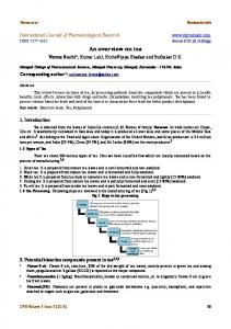
3 Conventional (classic) methods for fabrication of MGs parts The main “classic” methods for industrialization of MGs are: end-casting in copper molds and protected environment, die forging, atomization for obtaining MG bubbles, selective laser melting, imprinting in molds. Thermoplastic shaping in the supercooled temperature region. These methods are suitable for producing high value-added precision components but the problems still exists: high cost and limited lifetime of tools, the crystallization of MGs Actually methods (thermoplastic shaping, casting and die forging) are limited by low flexibility and higher costs of tools and accessories. A synthesis of classical methods for manufacturing the MGs parts is illustrated in Fig.2 [5, 11,12]
Fig.2. Conventional methods for manufacturing MGs parts. [5, 11, 12]
3
MATEC Web of Conferences 112, 03003 (2017)
DOI: 10.1051/ matecconf/201711203003
IManE&E 2017
Another usual method for manufacturing MGs micro-parts is the hot embossing method, schematized in Fig.3 [ 1]
Fig.3. Schematics of the hot-embossing process. (reproduced with permission from[1]© 2016Elsevier)
Recent research shows that by application of an electric current pulse in the presence of a normally directed magnetic field can heat (by electrical resistance) a metallic glass to a softened state, while simultaneously inducing a large enough magnetic body force to plastically shape it. The heating and shaping is performed on millisecond timescales, effectively bypassing crystallization producing fully amorphous- shaped parts. This electromagnetic forming process may become a promising manufacturing platform for strong metals [13-15].
4 Non-conventional methods for fabrication of MGs parts 4.1 The cutting of MGs It exists some sporadically studies of the machining characteristics of MGs during cutting and drilling and found that although mechanical machining of MGs can obtain high dimensional accuracy and surface quality, some problems, such as oxidation and crystallization during high speed machining, still exists [16-20]. In [16] the ultra-precision turning of a Zr-based MG was investigated under various machining parameters (depth of cutting, feed rate, and spindle rate) .The influences of machining parameters on the turned surface of a Zr-based MG after observing the 3D morphologies of this surface were characterized. The results showed that the influence of the spindle rate on the surface morphologies is more substantial as compared to the depth of cutting and the feed rate. Scratch tests were conducted to further characterize the separation mechanism of the chips. The chips are torn off the surface of a MG because of inhomogeneous localized maximum shear stress. According to the sketch in Fig. 4 [16], three factors (depth of cut, feed rate, and spindle rate) can essentially affect the turning of a metallic glass . Unfortunately, the excellent comprehensively mechanical properties of the Zr -based metallic glass lead to a severe abrasion of the diamond tool.
4
MATEC Web of Conferences 112, 03003 (2017)
DOI: 10.1051/ matecconf/201711203003
IManE&E 2017
Fig.4. The schematic of the ultra-precision turning of a Zr-based MG. (adapted with permission from [16]© 2015 Elsevier )
The cut-ability of Zr&Pd-based MGs by lathe was examined using different tool tip materials (diamond, CBN, ceramics and cermet), nose radii of the tip 0.4, 0.8 and 1.2 mm , feed speed ( f =0.05mm/rev) and cutting speeds (V=5-150 m/min). From the chip observation results, the mechanisms that the roughness on the turned surface of the MGs exhibited the precise finishing level. The chips slipped off at planar and evenly fine spaced slip planes controlled only by a maximum shearing stress. The cutting force became constant and chattering was not generated. As the MGs are generally difficult to produce the plastic deformation in addition to the slipping off behavior of the MGs, the MGs were easily cut off along the shape of the tool tip. A built-up edge did not occur in the MG workpieces - Fig.5 [17].
Fig.5. Chip formation mechanism of MG at turning operation. (adapted with permission [17] © 2005 Elsevier)
The severe tool wear because of the high hardness of MGs and the formation of built-up edge due to the adhesion between the chip and tool in the contact region affected the machining quality. Furthermore, for hard-brittle MGs with hardness over 10 GPa but fracture toughness less that 10 MPa , mechanical machining is more challenging. More suitable methods are greatly desired to machine MGs for their wider applications. 4.2 Fabrication of metallic glass ordered at large scale A recent and totally unconventional method for obtain a metallic glass that is ordered at a large scale was reported in a study conducted by Geophysical Laboratory (Carnegie Institution for Science) [21]. It was created a single crystal by applying 25 GPa of pressure (equivalent of 1800 tons per square inch) to the cerium–aluminum MG and the new order formed is preserved even when the glass is restored to ambient pressure. In Fig. 6 is schematized the experiment in where was fabricated a long range ordered (LRO) metallic glass.
5
MATEC Web of Conferences 112, 03003 (2017)
DOI: 10.1051/ matecconf/201711203003
IManE&E 2017
Fig.6. The schematic of fabrication of a large range ordered (LRO) metallic glass. [21]
4.3 The welding of metallic glass parts Because amorphous metal formation requires specific critical cooling rates, the part size and thickness are limited; however, these limitations can be overcome with welding. Welding possibilities and the weldability of MGs was recently studied in [22-23]. In [22], a Zr-based metal glassy alloy was successfully welded by small-scale resistance spot welding (RSW). In [23], the similar and dissimilar friction welding of tubular Zr-based MGs to amorphous and crystalline metals have been performed and compared with the cases of MG rods. A successful joining of the bulk metallic glass (BMG) to crystalline metals could be obtained for certain pairs of the material combination through the precise control of friction conditions. Electron beam welding method is industrially used by Liquidmetal Technologies -Fig. 7[24].
Fig.7. Electron beam welded butt-joint used by Liquidmetal Technologies Inc. [24]
4.4 The painting and coating of metallic glass parts MG parts can be painted with a range of traditional techniques and can also be processed through Physical Vapor Deposition (PVD) processes. Painting requires the same cleaning and surface preparation similarly to the other metallic surfaces. The paint baking cycle temperatures above 250°C could affect the amorphous structure of the material. PVD processes are used to apply high-purity coatings such as titanium, chromium, and aluminum to MG parts. In the PVD process, these coating materials are either evaporated by heat or bombarded with ions (sputtering). While the PVD coating metal is being vaporized, a reactive gas is introduced which forms a compound with the metal vapor and is deposited on the metal parts as a thin and highly adherent coating, Fig.8 [24].
6
MATEC Web of Conferences 112, 03003 (2017)
DOI: 10.1051/ matecconf/201711203003
IManE&E 2017
Fig.8. Metallic glass components industrially painted and coated. [24]
4.5 The electrical discharge machining (EDM) of metallic glass parts Considering the limited size of MGs and their main applications in precision and microcomponents, the micro-electrical discharge machining (M-EDM) may be a good choice for machining MGs. However, M-EDM is an electro-thermal process and MGs are very sensitive to temperature. A small number of recent researches [25-29] indicated that severe crystallization happened during EDM of MG because of high electrical discharge energy. It was revealed that crystallization of MGs occurs on the top surface in EDM. The penetration depth of the thermal damage into the bulk material is actually less studied and less known. The microstructural changes of MGs in heat affected zone during M-EDM have not been clarified. Also, as a disadvantage, the EDM machining is a low productivity process.
5 Conclusions The machinability of MGs has been given less attention, although it is seems to become very important from the perspective of industrialization. It were sporadically studied the machining characteristics of MGs during cutting and drilling and found that although mechanical machining of MGs can obtain high dimensional accuracy and surface quality, some problems, such as oxidation and crystallization during high speed machining, still exists. Some recent researches shows that micro-electrical discharge machining (M-EDM) is suitable for machining hard-brittle materials and can be used for production of micro-parts and three dimensional structures such as micro-holes, micro-gears, micro-array, and microtools.
References 1. N. Li, W. Chen, L. Liu, JOM, 68 (4), 1246-1261 (2016) 2. W. Klement, R.H. Willens, P. Duwez, Nature 187 (4740), 869–70 (1960) 3. P. Duwez, Top. Appl. Phys. 46 19–23 (1981) 4. M. Telford, Materials today, 7 (3), 36-43 (2004) 5. E. Axinte, MaterDesign, 35, 518-556 (2012). 6. M.D. Demetriou, M.E. Launey, G. Garrett, J.P. Schramm, D.C. Hofmann, W.L. Johnson, R.O. Ritchie, Nature Materials 10 (2), 123-128 (2011) 7. M.M. Trexler, N.N. Thadhani, Progr Mater Sci. 55, 759–839 ( 2010) 8. D.C. Hofmann, J.-Y. Suh, A. Wiest, G. Duan, M.-L. Lind, M.D. Demetriou, W.L. Johnson, Nature, 451, 1085–9 (2008) 9. K.L. Edwards, E. Axinte, L.L. Tabacaru, MaterDesign, 50, 713-723 (2013) 10. E. Axinte, Y. Wang, L.Tabacaru, N. Radwan, Recent Patents on Mat. Sci. J., 9 (1), 2-19 (2016) 11. K.J. Laws, B. Gun, M. Ferry, Mat. Sci. & Eng A, 475 (1), 348-354 (2008) 12. P. Ramasamy, A. Szabo, S. Borzel, J. Eckert et al., Scientific Rep. 6 (2016)
7
MATEC Web of Conferences 112, 03003 (2017)
DOI: 10.1051/ matecconf/201711203003
IManE&E 2017
13. G. Kaltenboeck, M.D. Demetriou, S. Roberts, W.L. Johnson, NatComm 7 (2016) 14. G. Kaltenboeck et al, Sci. Rep. 4 6441 (2014) 15. W.L. Johnson et al, Science 332, 828-833 (2011) 16. D.X. Han, G. Wang, J. Li, K.C. Chan et al, J. Mater. Sci. Technol. 31, 153-158 (2015) 17. K. Fujita, Y. Morishita, N. Nishiyama, H. Kimura, A. Inoue, Mater. Trans. 46, 2856-2863 (2005) 18. M. Bakkal et al, Intermetallics 12, 195-204 (2004) 19. H. Huang, H.W. Zhao, C.L. Shi, B.D. Wu et al, AIP Adv. 2 /042193 (2012) 20. T. H. Li, P. H. Tsai, K. T. Hsu, Y. C. Liu, J. S. C. Jang, J. C. Huang, Intermetallics, 78, 17-20 (2016) 21. Q. Zeng, Y. Ding, W. L. Mao, W. Yang, S. V. Sinogeikin, J. Shu, H. Mao, J. Z. Jiang, Phys Rev Lett. 104 (10), 105702 (2010) 22. K. Fujiwara, S. Fukumoto, Y .Yokoyama, M. Nishijima, A.Yamamoto, Mater Sci Eng A, 498, 302–307 (2008) 23. H.S. Shin, J.S. Park, Y. Yokoyama, J Alloys Compd 504S, 275–278 (2010) 24. Liquidmetal® Design Guide 3.0 ,( Liquidmetal Technologies, 2015) 25. D. Wang, W.S. Zhao, L. Gu, X.M. Kang, J. Mater. Process. Tech. 2113-11 (2011) 26. H. Huang, J.W. Yan, Appl. Surf. Sci. 355, 1306-1315 (2015) 27. S.F. Hsieh, S.L. Chen, M.H. Lin, S.F. Ou et al, J. Mater.Res. 28, 3177-3184 (2013) 28. D. Wang, W.S. Zhao, L. Gu, X.M. Kang, J. Mater. Process. Tech. 2113-11 (2011) 29. J.W. Yan, K. Watanabe, T. Aoyama, CIRP Ann.-Manuf. Techn. 63209-212, (2014)
8