demonstration of this network management application in a laboratory-based .... the SNMP-based solution for VDTNs network monitoring. This testbed, called ...
Globecom 2012 - Ad Hoc and Sensor Networking Symposium
An SNMP-based Solution for Vehicular Delay-Tolerant Network Management Bruno F. Ferreira∗ , Jo˜ao N. Isento∗ , Jo˜ao A. Dias∗ , Joel J. P. C. Rodrigues∗ , Liang Zhou∗† ∗ Instituto
de Telecomunicac¸o˜ es, University of Beira Interior, Covilh˜a, Portugal University of Posts and Telecommunications, China {bruno.ferreira, joao.isento, joao.dias}@it.ubi.pt, {joeljr, liang.zhou}@ieee.org † Nanjing
Abstract—Vehicular delay-tolerant networks (VDTN) assumes the use of the delay-tolerant network (DTN) concept for vehicular communications in order to cope several issues, such as highly dynamic network topology, short contact durations, disruption, intermittent connectivity, variable node density, and frequent network fragmentation. These challenging characteristics of vehicular networks affect the design and construction of a network management solution for VDTNs. The standard simple network management protocol (SNMP) is widely used on conventional networks and it is not directly deployable on VDTNs. Then, this paper proposes an SNMP-based solution for VDTNs supporting load-related information collection from VDTN nodes using SNMP. It presents the design and the demonstration of this network management application in a laboratory-based testbed. Index Terms—Vehicular Delay-Tolerant Networks; VDTNs; Network Management; Performance Assessment; Testbed.
I. I NTRODUCTION Vehicular communications have been the focus of an increasing interest in the last few years. In part, this interest is due to the potential applications of these networks that include, but not limited to, road safety, driving assistance, road traffic optimization, monitoring, and a wide variety of commercial and entertainment applications. They can also be used to provide connectivity to remote/rural communities and regions, and support for communication between rescue teams in disaster situations. Contrary to conventional networks, vehicular networks present some particular challenges that are receiving attention for the scientific community [1]. In particular, they have a highly dynamic network topology, variable node density, and are characterize by short contact durations. Limited transmission ranges, radio obstacles, and interferences, turn these networks prone to disruption, intermittent connectivity, and significant loss rates. Due to these particular issues, vehicular communications experience frequent partition (i.e., end-to-end connectivity may not exist). A variety of factors including node heterogeneity, node interactions, node cooperation, limited network resources, and energy constraints also add additional challenges. Vehicular ad hoc networks (VANETs) [2] are a subset of mobile ad hoc networks (MANETs) where mobile nodes are
978-1-4673-0921-9/12/$31.00 ©2012 IEEE
vehicles. In VANETs, taking into account the type of node under communication with a mobile node, communication can be classified as a vehicle to vehicle (V2V) or vehicle to infrastructure (V2I). This kind of networks assumes that end-to-end connectivity is available. Therefore, they are not able to deal with network partitions, disconnection, or long time delays. These limitations were solved by the store-carryand-forward paradigm proposed for delay-tolerant networks (DTNs). In a DTN-based network [3], the physical motion of vehicle and opportunistic contacts is harnessed to transport data between disconnected parts of the network. Data is stored and carried until a contact opportunity with other node is available. When a contact occurs, data are forwarded to that node, based on a routing protocol, trying to reach the destination as soon as possible and increase data delivery [4]. Vehicular delay-tolerant networks present a new approach for vehicular communications employing the store-carry-andforward paradigm from DTNs [5]. VDTN architecture places the bundle layer under the network layer introducing an IP over VDTN approach. This architecture uses out-of-band signaling, with control and data planes separation. The data plane is responsible for the assembling, transferring, and processing
Terminal Node
Terminal Node
Application
Application
Application Data Transport
Transport
Segments Network
Datagrams BAD
Mobile/Relay Node
Mobile/Relay Node
Network
BSC
BAD
BSC
BAD
BSC
BAD
BSC
MAC
MAC
MAC
MAC
MAC
MAC
MAC
MAC
PHY
PHY
PHY
PHY
PHY
PHY
PHY
PHY
One bundle
One frame
Setup Message
Data Bundle
BSC - Bundle Signaling Control
Persistant Storage MAC - Media Access Control
BAD - Bundle Aggregation and De-aggregation
PHY - Physical
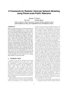
Fig. 1. Messages and Data Bundles transmissions between VDTN nodes, from a source to a destination.
268
data bundles while the control plane transmits and processes the setup messages and performs resources reservation hope by hope until the destination. The VDTN layered architecture may be seen in Figure 1. The bundle layer is split into two sub-layers: the bundle signaling control layer (BSC) and the bundle aggregation and de-aggregation layer (BAD). BSC executes control plane functions as setup message exchange, resource reservation, among others. BAD is responsible for data plane functions that deal with data bundles. At the source terminal node, the BAD layer assembles data units form network layer (IP packets) with similar properties in one unique data bundle. The bundle is then transmitted over a VDTN network, from source to destination, which may involve several intermediate nodes. When a bundle reaches its destination, the BAD layer does the reverse process, deaggregating the bundle into individual IP packets. Conventional network management systems use different solutions. Nevertheless, the standard simple network management protocol (SNMP) [6] is widely on used networks management and it allows the management information exchange between a network manager and the agents. SNMP is a widely common used protocol for fixed network management (monitoring and configuration). The data are collected by the network management system (NMS) requests to the managed network devices. All objects that can be accessed are described in a management information base (MIB). NMS is responsible to keep the entire network operational, monitoring, and control the network devices. Due to the unique features provided by VDTNs, such as network intermittency, disconnection, and long delays, the SNMP cannot be directly applied. Then, this paper proposes a network management solution for VDTNs. The proposed monitoring system can be considered as an SNMP-based system for VDTNs. This approach uses the SNMPv3 protocol, compatible with other management solution. In VDTN architecture there was only one NMS responsible for all the network management. The communication between NMS and network devices was established by SNMP messages. The proposed solution is evaluated through a VDTN laboratory testbed used for conducting experiments and evaluates the SNMP-based solution for VDTNs network monitoring. This testbed, called VDTN@Lab [7], provides a framework for demonstration and validation of the VDTN architecture, allowing the development, performance evaluation, and validation of new services, protocols, and applications [8]. The remainder of this paper is organized as follows. Section II reviews the related literature about other monitoring system approaches and applications used in vehicular communications. The design of the system and the software usability is presented in Section III. Section IV demonstrates the monitoring system on a laboratory testbed (VDTN@Lab). Finally, Section V summarizes the main conclusions of this work and suggests some topics for future work.
II. R ELATED W ORK The proposal of a network monitoring system for VDTNs was based on other available solutions proposed for conventional and mobile networks. These approaches will be considered in this section. An SNMP-based solution for monitoring a MANET network was proposed in [9]. It uses a smaller implementation of SNMP considering the limitations from this kind of networks. First, it describes the obstacles that hinder the direct implementation of the SNMP protocol in MANETs, in particular, the short time contacts and dependence of wireless communications. The MANET uses the optimized link state routing protocol version 2 (OLSRv2) which offers three basic processes that helps the SNMP implementation: Neighborhood Discovery, MultiPoint Relay (MPR) Flooding, and Link State Advertisements. Neighborhood discovery (NHDP) allows network nodes to discover the routers that can establish bi-directional communication. MPR Flooding is the process whereby each router is able to conduct network-wide broadcasts. Link state advertisements let network nodes to determine the state of each link on the network. Consequently, it allows all routers to calculate shortest end-to-end paths. The OLSRv2 management system architecture considers three MIB modules: NHDPMIB, OLSRv2-MIB, and REPORT-MIB. Both NHDP-MIB and OLSRv2-MIB are based on different groups, allowing changing protocol parameters and monitoring the router state. In [10], the authors present an overview of the main available management architecture approaches for MANETs and raise their theoretical and practical limitations. They discuss issues related with building efficient management architecture adaptable for MANETs. This study is composed by three different models that can be applied to mobile ad hoc networks. The first one is the SNMP-based model. Hierarchical model of management based on SNMP can perform, more accurately, complex tasks of management and management decisions. Although it presents several disadvantages, such as high message overhead or if some node has a failure in a fragmented network, all nodes are left without management functionalities. Because of the self-organized characteristic of MANETs, the management task should be distributed. The second available model is the Policy-based approach. The policy-based system has the following components: a policy enforcement point (PEP), a policy decision point (PDP), a policy repository (PR), and a tool of political management. The PDP task retrieves and interprets political information, and passes it to the PEP. The policy repository is the place where all the policies are stored and made by PDPs. Policy-based management network offers this feature through the implementation and enforcement of policies previously defined by the network manager. Otherwise, the complexity of establishing control makes its implementation very difficult. The third model, called a self-managing based model, assumes that an autonomic network proposes the solution of self-management. This approach leads to network management architecture able to take into account the autonomous nature
269
of MANETs. A disadvantage of this approach comes to the fact that it can be too much complex to compute nodes with limited resources and sensor nodes need to be dedicated to specific management functions. The monitor for mobile ad hoc networks (MMAN) [11] was proposed for a network management solution used on MANETs. First, the authors present the major features showing how MMAN is better than previous monitoring approaches. MMAN uses multiple monitoring nodes collaborating to produce a snapshot of network conditions. MMAN relies on several monitoring stations that combine information to maintain an accurate up-to-time view of the current MANET topology. A number of monitoring units (MUs) are deployed throughout the MANET. These MUs are responsible for gathering information regarding network performance. After, the information gathered by the MUs is delivered to the management nodes, where they are analyzed and presented on a graphical user interface. To allow these monitoring capabilities of MUs, each one is equipped with two network interfaces. One wireless interface is responsible for packets transfer over MANET while the other (which can be wireless or wired) is used to change information between MUs. Thus, MMAN does not overload the MANET traffic with this additional monitor traffic. To validate and demonstrate this monitoring system, it was created a MANET with 10 nodes using IEEE 802.11b/g. The same MANET was monitored using two MUs with 80%90% total coverage. MMANs performance was evaluated from the following perspectives: ability to produce a dynamic and up-to-time picture of the MANET topology; ability to present traffic load information for covered nodes; ability to present as assessment of cooperation level for nodes under the coverage area of the MUs; and assessment of storage capability and CPU processing requirements for management nodes. Diagnostic interplanetary network gateway (DING) protocol was developed to introduce monitoring capabilities in DTN technology [12]. DING uses a subscription-based model for information distribution to cope the connectivity of DTN. The goal of this work is to implement mechanisms for network monitoring on Bundle and lower layers that are not addressed by available mechanisms. The authors set up a DTN2 with 3 nodes, involving a several configurations steps. They evaluated this testbed switching DTN traffic between nodes using variable connectivity and bundle sizes. After this setup work, the next step is the implementation of network monitoring capabilities that would allow observer the status of the network and network traffic exchange at the DTN level. In original DTN2 implementation, no network monitoring functionality is built in. On this proposal, the nodes produce several log files created by shell scripts created over DTN2. Several parameters are considered because all of them are important for describing the status of the network. These parameters are the following: DTN nodes uptime, that shows whether a DTN node is running or not; Bundle Traffic, that shows a number of data related to Bundle traffic, such as how many Bundles may be received by a node and forward, how many are delivered, deleted or expired; and link statistics, that describes the status of each
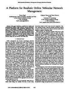
link between nodes, showing the speed of data transmission and the total of transferred data. III. VDTN M ONITORING S YSTEM This section presents the proposed SNMP-based solution for VDTNs network management. It includes all the important aspects to deploy the SNMP protocol on VDTNs given their particular characteristics. This section considers three subsections. First, the system architecture and main operations will be described. After, the construction of a MIB file, which keeps information of network nodes and several metrics for performance assessment of VDTN networks, will be present. The last subsection presents the format of SNMP message used in this solution. A. System Architecture The SNMP deployment over a VDTN network has some similarities with conventional SNMP solutions. The NMS is embedded on a terminal node system and it will generate SNMP messages that will be aggregated in bundles to be transmitted over the VDTN network. The network management becomes an essential activity to guarantee its continuous operation and to ensure the high grade of quality services provided. So the VDTN network has a network management station (NMS) that allows messages exchange (sending and receiving) with the different network nodes. Through this application the manager can control and administrate the entire network once they can communicate with all nodes. VDTN NMS can perform a superficial management when data are analyzed, like the system information and the SNMP messages exchanged. It also can monitor a new group implemented in a MIB file, the VDTN group, described on the next subsection. VDTNs may assume full cooperation among nodes. Following this approach, all of them are prepared to exchange SNMP messages in order to obtain not just a partial, but
Network Management Station SNMP Entity SNMP Application
Terminal Node
SNMP Manager Bundles MP SN
MP SN
SNMP Messaging
SN MP
SNMP Agent
SNMP Agent
SNMP Agent
MIB
MIB
MIB
SNMP Entity
SNMP Entity
SNMP Entity
Terminal Node
Relay Node
Mobile Node
Fig. 2. Communications between VDTN nodes and the Network Management Station.
270
an entire control of the VDTN network. With this developed architecture, all the network nodes (terminals, relays, and mobiles) have a SNMP agent that contains a MIB file that allows communication between NMS and the respective network node in order to obtain a more efficient network management. Figure 2 illustrates the interaction that occurs between the NMS and the network element (terminal, relay, or mobile node). NMS exchange SNMP messages with network elements that contains a MIB file and it is responsible for monitoring, reporting, and deciding if there was a problem and the network element (agent) is responsible to answer the requests of NMS, sending values back or making changes. B. Management Information Base (MIB) In this subsection, a description of management information base (MIB) files will be considered and all the process until the final step, the MIB creation, will be explained. MIB is a virtual database that keeps information about some management station in SNMP managed network. This file includes a set of variables displayed in a hierarchical structure (tree). A MIB contains information about properties and definitions that an agent supports, which information is represented by objects or variables. To represent the MIB structure, the ASN.1 (abstract syntax notation one) is used. In a few words, MIB serves as a data dictionary or codebook to assemble and interpret SNMP messages. Before creating the MIB structure an approach that allowed creating the MIB file successfully was followed. Figure 3 illustrates all the four steps that were followed to create a MIB module that corresponds to all the system requirements. The first step was carefully defined and what kind of objects should be analyzed in our network. After that, a document with the specifications of MIB object to quickly understand the purpose of any object was created. Then, it
Analyse the requirements to be managed/administrated
List of manageable objects to be included in the MIB
Organize MIB objects into groups
Write MIB file
Fig. 3.
The MIB file creation process.
was organized into groups and, finally, writes the MIB file. It is expected that additional MIB objects will be defined and implemented over the time to provide monitoring and control needs of new or changing components in network. In order to make the NMS an application more robust and user-friendlier, a module that allow analyze the numeric data received by NMS on a graphic interface was developed. Through this implementation it is possible to detect and identify anomalies in the network or nodes performance degradation. It was been created a module aside this MIB. This module acts as an intermediary between SNMP application and VDTN nodes application, in order to get or set specific information in the nodes. This new module is the center of all monitoring because in there are allocated all the managed objects to the control of all nodes as vehicular network nodes. With this implementation is now possible monitor a set of important proprieties in vehicular network, Messages allocated in each node buffer (messages ids that are in a node buffer), Messages discarded by node (messages ids that are discarded by node), Number of contacts that were established by managed node and other network node, Contact time between them, Messages delivered (messages ids delivered by managed node), Battery Status (reports the energy level of managed node), Buffer Space (the buffer space available to node receive messages). C. SNMP Message The SNMP protocol allows the exchange of multiple messages in a network, each one with a different purpose. SNMP uses four basic operations to establish the communication between NMS and an agent - GET, SET, GETNEXT, and TRAP. With these messages it is possible to NMS request or change object values from a management node. Traps are used to report a notification. Figure 4 illustrates the overall SNMP message used in the proposed VDTN management system. The description, below, will explain the main fields of this message format. The Message Version Number describes the SNMP version number of this message; it is used for ensuring compatibility between versions. For SNMPv3, its value is 3. Message Identifier is a number used to identify an SNMPv3 message and to match response messages to request messages. Maximum Message Size sets the maximum size of message that its sender can receive. The Scoped PDU contains the PDU to be transmitted, along with parameters that identify an SNMP context, which describes a set of management information accessible by a particular entity. This PDU contains a Context Engine ID used to identify to which application the PDU will be sent for processing. In this solution only one application is considered. It also includes a Message Body. It is composed by several fields that indicate the operation (GetRequest, SetRequest, Trap, ...) requested by NMS. This operation is defined in the PDU Type. Request Identifier is a number used to match requests with replies. Error Status uses an integer value that is used in a Response-PDU to tell the requesting SNMP entity the result of its request. A zero value indicates that
271
0
8
16
24
32
Message Version Number 8
6
0
Message Identifier Maximum Message Size
+
Reportable Flag
Reserved
Privacy Flag
Authentication Flag
Reserved Flags
Message Security Model Message Security Parameters 0
Scoped PDU
Context Engine ID
8
16
24
32
PDU Type Request Identifier
Context Name
Error Status Message Body (PDU)
Error Index PDU Variable Bindings
Fig. 4.
Fig. 6.
SNMP General Message Format.
no error occurred and the other values indicate what sort of error happened. Variable Bindings is a set of name-value pairs identifying the MIB objects in the PDU. In the case of messages, other than requests, they contain their values. The security fields of the SNMPv3 message were not considered on this work. IV. S YSTEM D EMONSTRATION The management system was experimented and evaluated in a VDTN testbed, called VDTN@Lab. Three terminal nodes, two relay nodes, and four mobile nodes were considered on the testbed. The terminal nodes are located at different edges of the laboratory, while relay nodes are placed at crossroads. Mobile nodes have a random movement across roads. All nodes are equipped with Bluetooth and IEEE 802.11b/g devices to allow the use of different network technologies to demonstrate the out-of- band signaling with the separation of control and data planes. All nodes also have a set of software modules deployed to emulate the VDTN services. The management application was deployed on the terminal 2, without any special criteria. On relay and mobile nodes the SNMP Agent and the respective MIB file was deployed. All the SNMP solution directly interacts with the VDTN software modules. Figure 5 illustrates the VDTN testbed and all its interactions.
VDTN Management Application.
Figure 6 shows the manager application of this SNMP solution. This application was embedded on VDTN terminal node application and, in this demonstration, only one terminal node can be a SNMP manager. It is assumed that the manager is aware of all of the testbed nodes. The application shows important information about the network. As may be seen in the figure, in (a) the application shows a list of all the network nodes. When a node is selected, the application displays the node information (b), if it is available, and the management application can perform a SNMP operation (c) on that node to acquire the required information (such as battery status, dropped bundles, etc.). This application with the information of all the testbed nodes will create a line chart (d) that displays a metric to evaluate the network performance. To demonstrate this SNMP management system at VDTN@Lab, several experiments whit the duration of one hour each one were performed. The main objective includes measuring the average delay and average number of hops between the creation of a request and the arrival of response to the manager node and a given node. The requests are performed along the testbed experiments and all of them are sent in broadcast to all the nodes. The Epidemic routing protocol is used on this study. Figure 7 shows the SNMP message average delay between the creation of SNMP get message and the arrival of correspondent answer. The results show an acceptable delay time for getting the requested information from all the network nodes. As the considered mobile nodes movement is random, the found results suggest that the delay time is related to the
Average Delay (sec)
300 250 200 150 100 50 0 Term. 1
Fig. 5.
Illustration of the VDTN@LAB testbed.
Term. 3
Relay 1
Relay 2 Mobile 1 Mobile 2 Mobile 3 Mobile 4
Fig. 7. SNMP message Average Delay between its creation and the corresponding answer for all the network nodes.
272
Average number of hops
12
R EFERENCES
10 8 6 4 2 0 Term. 1
Term. 3
Relay 1
Relay 2 Mobile 1 Mobile 2 Mobile 3 Mobile 4
Fig. 8. Average number of hops of SNMP messages for all nodes of testbed.
relative position of nodes compared to terminal node 2. For example, the Terminal node 1 has the worst average delay because it is positioned at the most distant point of the testbed scenario. Figure 8 shows the average number of hops that the requests and corresponding answers perform until reaching the SNMP manager. Once again, these results emphasize the fact that the position of the nodes reflects the performance of the network. Both results show that performance of SNMP on mobile nodes is very similar. This is due to the fact of the random movement of the mobile nodes and when a request is sent the position of the mobile nodes is never the same. V. C ONCLUSION AND F UTURE W ORKS This paper presented a network management solution for VDTNs using the standard SNMP protocol. A monitoring system is very useful to verify the proper network working, check possible network anomalies, and collect statistic data for the network administrator. Aiming to provide a robust mechanism for network monitoring, it was deployed in a laboratory testbed VDTN@Lab for validation and demonstration. It was shown that solution works properly and it is ready for use. Nevertheless, the system may be improved in further works. In this demonstration case study, the SNMP application is embedded a VDTN terminal node application. Then, the migration of this application for being independent and accessed outside VDTN network, such as in the Internet, can be considered for future work. The security mechanisms of the SNMPv3 Protocol should also be included in future works.
[1] S. Yousefi, M. S. Mousavi, and M. Fathy, “Vehicular Ad Hoc Networks (VANETs): Challenges and Perspectives,” in 6th International Conference on ITS Telecommunications Proceedings, June 21-23 2006, pp. 761–766. [2] J. Jakubiak and Y. Koucheryavy, “State of the Art and Research Challenges for VANETs,” in 5th IEEE Consumer Communications and Networking Conference (CCNC 2008), 2008, pp. 912–916. [3] V. Cerf, S. Burleigh, A. Hooke, L. Torgerson, and R. Durst, “Delaytolerant networking architecture,” RFC 4838, April 2007. [4] P. Pereira, A. Casaca, J. Rodrigues, V. Soares, J. Triay, and C. Cervello-Pastor, “From Delay-Tolerant Networks to Vehicular Delay-Tolerant Networks,” Communications Surveys & Tutorials, IEEE Communications Society, pp. 1-17, ISSN: 1553-877X, DOI: 10.1109/SURV.2011.081611.00102. [5] V. Soares, F. Farahmand, and J. Rodrigues, “A Layered Architecture for Vehicular Delay-Tolerant Networks,” IEEE Symposium on Computers and Communications (ISCC 2009), pp. 122–127, 2009. [6] D. Harrington, R. Presuhn, and B. Wijnen, “An architecture for describing simple network management protocol (snmp) management frameworks,” RFC 3411, December 2012. [7] J. Dias, J. Isento, B. Silva, V. Soares, and J. Rodrigues, “Performance assessment of IP over vehicular delay-tolerant networks through the VDTN@Lab testbed,” EURASIP Journal on Wireless Communications and Networking, Hindawi, ISSN: 1687-1472, Vol. 2012, paper 13, February 2012, pp. 1-12, DOI: 10.1186/1687-1499-2012-13. [8] J. A. F. F. Dias, J. Rodrigues, and J. N. Isento, “Performance assessment of fragmentation mechanisms for vehicular delay-tolerant networks,” EURASIP Journal on Wireless Communications and Networking, Hindawi, ISSN: 1687-1472, Vol. 2012, paper 13, February 2012, pp. 1-12, DOI: 10.1186/1687-1499-2012-13. [9] U. Herberg, R. Cole, and J. Yi, “Performance analysis of SNMP in OLSRv2-routed MANETs,” in 7th International Conference on Network and Service Management (CNSM), 2011, 2011, pp. 1–5. [10] S. El brak, M. Bouhorma, and A. A Boudhir, “Network Management Architecture Approaches Designed for Mobile Ad hoc Networks,” International Journal of Computer Applications, vol. 15, no. 6, pp. 14– 18, Feb. 2011. [11] H. Kazemi, G. Hadjichristofi, and L. A. DaSilva, “MMAN - a monitor for mobile ad hoc networks: design, implementation, and experimental evaluation,” in Proceedings of the third ACM international workshop on Wireless Network Testbeds, Experimental Evaluation and Characterization, WiNTECH ’08:. ACM Request Permissions, Sep. 2008. [12] Papalambrou, “Monitoring of a DTN2 network,” Baltic Congress on Future Internet Communications (BCFIC 2011), pp. 116–119, 2011.
ACKNOWLEDGMENTS This work has been partially supported by the Instituto de Telecomunicaes, Next Generation Networks and Applications Group (NetGNA), Portugal, and by National Funding from the FCT Fundao para a Ciłncia e a Tecnologia through the PEst-OE/EEI/LA0008/2011 Project.
273