An XML representation of DAE systems obtained from continuous-time Modelica models Roberto Parrotto1
Johan Åkesson2,4
Francesco Casella3
1
Master’s student - Politecnico di Milano, Italy
[email protected] 2 Department of Automatic Control, Lund University and Modelon AB, Sweden
[email protected] 3 Dipartimento di Elettronica e Informazione, Politecnico di Milano, Italy
[email protected] 4 Modelon AB, Lund, Sweden
Abstract This contribution outlines an XML format for representation of differential-algebraic equations (DAE) models obtained from continuous time Modelica models and possibly also from other equation-based modeling languages. The purpose is to offer a standardized model exchange format which is based on the DAE formalism and which is neutral with respect to model usage. Many usages of models go beyond what can be obtained from an execution interface offering evaluation of the model equations for simulation purposes. Several such usages arise in the area of control engineering, where dynamic optimization, Linear Fractional Transformations (LFTs), derivation of robotic controllers, model order reduction, and real time code generation are some examples. The choice of XML is motivated by its de facto standard status and the availability of free and efficient tools. Also, the XSLT language enables a convenient specification of the transformation of the XML model representation into other formats. Keywords DAE representation, XML design
1.
Introduction
Equation-based, object-oriented modeling languages have become increasingly popular in the last 15 years as a design tool in many areas of systems engineering. These languages allow to describe physical systems described by differential algebraic equations (DAE) in a convenient way, promoting re-use of modeling knowledge and a truly modular approach. The corresponding DAEs can be used for different purposes: simulation, analysis, model reduction, optimization, model transformation, control system synthe-
sis, real-time applications, and so forth. Each one of these activities involves a specific handling of the corresponding differential algebraic equations, by both numerical and symbolic algorithms. Moreover, specialized software tools which implement these algorithms may already exist, and only require the equations of the model to be input in a suitable way. The goal of this paper is to define an XML-based representation of DAE systems obtained from object-oriented models written in Modelica [16], which can then be easily transformed into the input of such tools, e.g. by means of XSLT transformations. The first requirement of this system representation is to be as close as possible to a set of scalar mathematical equations. Hierarchical aggregation, inheritance, replaceable models, and all kinds of complex data structures are a convenient means for end-users to build and manage models of complex, heterogeneous physical systems, but they are inessential for the mathematical description of its behavior. They will therefore be eliminated by the Modelica compiler in the flattening process before the generation of the sought-after XML representation. However, the semantics of many Modelica models is in part defined by user-defined functions described by algorithms working on complex data structures. It is therefore necessary to describe Modelica functions conveniently in this context. The second requirement of the representation is to be as general as possible with respect to the possible usage of the equations, which should not be limited to simulation. A few representative examples include: • off-line batch simulation; • on-line real-time simulation; • dynamic optimization [3]; • transformation of dynamic model with nonlinearities
3rd International Workshop on Equation-Based Object-Oriented Languages and Tools. October, 2010, Oslo, Norway. Copyright is held by the author/owner(s). The proceedings are published by Linköping University Electronic Press. Proceedings available at: http://www.ep.liu.se/ecp/047/ EOOLT 2010 website: http://www.eoolt.org/2010/
and/or uncertain parameters into Linear Fractional Representation formalism [7]; • linearization of models and computation of transfer
functions for control design purposes;
91
• model order reduction, i.e., obtaining models with a
smaller number of equations and variables, which approximate the input-output behavior around a set of reference trajectories [8];
A DAE system consists of a system of differential algebraic equations and it can be expressed in vector form as: F (x, ˙ x, u, w, t, p) = 0
• automatic derivation of direct/inverse kinematics and
advanced computed torque and inverse dynamics controllers in robotic systems [6]. From this point of view, the proposed XML representation could also be viewed as a standardized interface between multiple Modelica front-end compilers and multiple symbolic/numerical back-ends, each specialized for a specific purpose. In addition, the XML representation could also be very useful for treating other information concerning the model, for example using an XML schema (DTD or XSD) for representing the simulation results, or the parameter settings. In those cases, using a well accepted standard will result in great benefits in terms of interoperability for a very wide spectrum of applications. Previous efforts have been registered to define standard XML-based representations of Modelica models. One idea, explored in [14, 11], is to encode the original Modelica model using an XML-based representation of the abstract syntax tree, and then process the model through, e.g., XSLT transformations. Another idea is to use an XML database for scalable and database-friendly parameterization of libraries of Modelica models [17, 15]. The goal of this paper is instead to use XML to represent the system equations at the lowest possible level for further processing, leaving the task of handling aggregated models, reusable libraries etc. to the object-oriented tool that will eventually generate the XML representation of the system. In particular, this paper extends and complements ideas and concepts first presented in [5]. A similar approach has been followed earlier by [4], but has apparently remained limited to the area of chemical engineering applications. The paper is structured as follows: in Section 2, a definition of the XML schema describing a DAE system is given. Section 3 briefly describes a test case in which a model is exported from JModelica.org platform and imported in the tool ACADO in order to solve an optimization problem. Section 4 ends the paper with concluding remarks and future perspectives.
2.
XML schema representation of DAE systems
The goal of the present work is to define a representation of a DAE system which can be easily transformed into the input format of different purpose tools and then reused. A representation as close as possible to the mathematical formulation of equations is a solution general enough to be imported from the most of the tools and neutral with respect of the possible usage. For this reason concepts such as aggregation and inheritance proper of equation based object-oriented models have to be avoided in the representation.
(1)
where x˙ are the derivatives of the states, x are the states, u are the inputs, w are the algebraic variables, t is the time and p is the set of the parameters. The schema does not enforce the represented DAEs to have index-1, but this would be the preferable case, so that the x variables can have the proper meaning of states, i.e., it is possible to arbitrarily select their initial values. Preferring the representation of models having index 1 is acceptable considering that most of the applications for DAE models require an index-1 DAE as input. In addition, in case the equations of the original model have higher index, usually an index-1 DAE can be obtained by index reduction, so the representation of index-1 DAEs doesn’t drastically restrict the possible applications range. The formulation provided in equation (1) is very general and useful for viewing the problem as one could see it written on the paper, but it is not directly usable for intertools exchange of models. It is then necessary to provide a standardized mathematical representation of the DAE systems that relies on a standard technology: this justifies the choice of the XML standard as a base for our representation. Hence, a formulation that better suits with our goal is proposed. Given the sets of the involved variables • x˙ ∈ Rn : vector of time-varying state derivative vari-
ables • x ∈ Rn : vector of time-varying state variables • u ∈ Rm : vector of time-varying input variables • w ∈ Rr : vector of time-varying algebraic variables • p ∈ Rk : vector of bound time invariant variables (pa-
rameters and constants) • q ∈ Rl : vector of unknown time invariant variables
(unknown parameters) • t ∈ R: time variable
it is possible to define the three following different subsets for the equations composing the system. The system of dynamic equations is given by F (x, x, ˙ u, w, p, q, t) = 0
(2)
where F ∈ Rn+r . These equations determine the values of all algebraic variables w and state variable derivatives x, ˙ given the states x, the inputs u, the parameters p and q, and the time t. The parameter binding equations are given by p = G(p)
(3)
where G ∈ Rk . The system of parameter binding equations is assumed to be acyclic, so that it is possible to compute all the parameters by suitably re-ordering these equation into a sequence of assignments, e.g. via topological sorting. The
92
DAE initialization equations are given by H(x, x, ˙ u, w, p, q) = 0.
(4)
Ideally, for index-1 systems, H ∈ Rn+l , i.e., H provides n + q additional equations, yielding a well posed initialization problem with 2n + r + l unknowns and 2n + r + l equations. The initialization system is thus obtained by aggregating the dynamic equations (2) and the initialization equations (4) and determines the values of the states, state derivatives, algebraic variables and free parameters at some initial time t0 . 2.1
General design issues
The main goal is to have a schema: • neutral with respect of the model usage; • easy to use, read and maintain; • easy to extend.
To achieve the first goal a representation as close as possible to the mathematical one of the DAE is required, as discussed in the previous section. To achieve the other required properties, a design based on modularity yields a result easier to read and extend. The proposed design provides one different vocabulary (namespace) for every section of the schema. In this way, if a new section will be required, for example to represent information useful for a special purpose, and a new module can be added without modify the base schema. The Functional Mock-up Interface for Model Exchange 1.0 (FMI 1.0)[12] has been chosen as a starting point for the schema, with the main advantage of basing the work on an already accepted standard for model exchange. The FMI 1.0 specification already provides a schema containing a representation of the scalar variables involved in the system. This schema has been extended according to our goals by adding a qualified name representation for the variable identifiers, and by appending a specification of the DAE system. The new modules composing the schema with the corresponding namespace prefixes are: • expressions module (exp) • equations module (equ) • functions module (fun) • algorithms module (fun)
All these modules, whose detailed information are given in the next paragraphs, are imported in the FMI schema, to construct the composite schema. 2.2
FMI schema and variable definitions
The FMI standard is a result of the ITEA2 project MODELISAR. The intention is that dynamic system models of different software systems can be used together for simulation. The FMI defines an interface to be implemented by an executable called FMU (Functional Mock-up Unit). The FMI functions are called by a simulator to create one or more instances of the FMU, called models, and to run these
models, typically together with other models. An FMU may either be self-integrating (co-simulation) or require the simulator to perform numerical integration. Alternatively, tools may be coupled via co-simulation with network communication. The intention is that a modeling environment can generate C-code of a dynamic system model that can be utilized by other modeling and simulation environments. The model is then distributed in packages containing the C-code of the dynamic system, an XML-file containing the definition of all variables in the model, and other model information. For the present work, the FMI XML schema for description of model variables has been reused and extended. The FMI XML schema already provides elements and attributes to represent general information about the model, such as name, author, date, generating tool, vendor annotations, but the core is the representation of the scalar variables defined in the model. It is important to notice that the FMI project is developed for the exchange of models for simulation purpose only, and not all the information present in the schema should be used in our case. Thus it is necessary to point out how to correctly use it for the purposes of this work. Firstly, the FMI schema allows the definition of Real, Integer, Boolean, String and Enumeration scalar variables. In our case, the equations (2) - (4) are all realvalued, and all time varying variables are real variables. The scalar variables definition provided by the FMI XML schema also includes attributes describing the causality (input, output, internal) and variability (constant, parameter, discrete, continuous) of the variable. Since our representation is concerned with continuously time varying DAEs only, then the definition of discrete variables should not be allowed. A full documentation of the FMI XML schema is available in [12]. The proposed representation should be neutral with respect to the application context. This also means that variable identifiers should be represented in a general way. It may happen that the tool exporting the model accepts identifiers with special characters that the importing tool does not allow. Furthermore, in the definition of user-defined functions (see a detailed discussion in Section 2.4) more complex types than scalar variables, such as array and records, are allowed. The index of an array can be a general expression, and representing the array’s element by a string, e.g. "x[3*5]", would require to write an ad-hoc parsing module in the importing tools. In the same manner the exporting tool can support a notation to describe array subscripts or record fields that is different from the one used by the importing tool. For all these reasons a structured representation for qualified names, that includes only the necessary information and avoid language dependent notations is introduced. A complex type QualifiedName is then defined and it will be used as a standard representation for names in all the schema. The QualifiedName complex type expects that the identifier is broken in a list of parts, represented by QualifiedNamePart elements. QualifiedNamePart holds a string attribute "name"
93
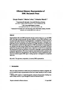
and an optional element ArraySubscripts, to represent the indices of the array element. ArraySubscripts elements provide a list of elements, one for each index of the array (e.g. a matrix has an ArraySubscripts element with two children). Each index is generally an expression, represented by IndexExpression, but usually languages support definition of array variables with undefined dimensions, represented by an UndefinedIndex element. Conventionally, the first element of an array has index 1. In the proposed representation, definition of array variables is allowed only in user-defined functions. Hence, the original representation of scalar variables provided by the FMI XML schema is extended in order to support the definition of variable names as qualified names, that will be the standard representation of identifiers in the whole schema.
Figure 1. Scalar variable definition extended from the original FMI definition
2.3
Expressions
All the expressions are collected in the exp namespace. The elements in the exp namespace represent all the mathematical scalar expressions of the system: • basic algebraic operators like Add, Mul, Sub, Div and
the factor function Pow. • Basic logical comparison operators like >, >=,