Application note. STM32™ microcontroller system memory boot mode ... This
application note presents the general concept of the bootloader. It describes the.
AN2606 Application note STM32 microcontroller system memory boot mode
Introduction The bootloader is stored in the internal boot ROM memory (system memory) of STM32 devices. It is programmed by ST during production. Its main task is to download the application program to the internal Flash memory through one of the available serial peripherals (USART, CAN, USB, I2C, SPI, etc.). A communication protocol is defined for each serial interface, with a compatible command set and sequences. This document applies to the products listed in Table 1. They are referred as STM32 throughout the document. Table 1. Applicable products Type
Part number or product series
STM32F0 Series: STM32F03xxx, STM32F04xxx, STM32F05xxx, STM32F07xxx, STM32F09xxx STM32F1 Series. STM32F2 Series. STM32F3 Series: STM32F301xx, STM32F302xx, STM32F303xx, STM32F318xx, STM32F328xx, STM32F334xx, STM32F358xx, STM32F373xx, STM32F378xx, STM32F398xx STM32F4 Series: STM32F401xx, STM32F405xx, STM32F407xx, STM32F410xx, STM32F411xx, STM32F412xx, STM32F413xx, STM32F415xx, STM32F417xx, STM32F423xx, STM32F427xx, STM32F429xx, STM32F437xx, STM32F439xx, STM32F446xx, STM32F469xx, Microcontrollers STM32F479xx STM32F7 Series: STM32F722xx, STM32F723xx, STM32F732xx, STM32F733xx, STM32F745xx, STM32F746xx, STM32F756xx, STM32F765xx, STM32F767xx, STM32F769xx, STM32F777xx, STM32F779xx STM32H7 Series: STM32H743xx, STM32H753xx STM32L0 Series. STM32L1 Series: STM32L100xx, STM32L151xx, STM32L152xx, STM32L162xx STM32L4 series: STM32L431xx, STM32L432xx, STM32L433xx, STM32L442xx, STM32L443xx, STM32L451xx, STM32L452xx, STM32L462xx, STM32L471xx, STM32L475xx, STM32L476xx, STM32L486xx, STM32L496xx, STM32L4A6xx
This application note presents the general concept of the bootloader. It describes the supported peripherals and hardware requirements to be considered when using the bootloader of STM32 devices. However the specifications of the low-level communication protocol for each supported serial peripheral are documented in separate documents as referred in Section 1: Related documents.
July 2017
DocID13801 Rev 31
1/283 www.st.com
1
Contents
AN2606
Contents 1
Related documents . . . . . . . . . . . . . . . . . . . . . . . . . . . . . . . . . . . . . . . . . 16
2
Glossary . . . . . . . . . . . . . . . . . . . . . . . . . . . . . . . . . . . . . . . . . . . . . . . . . . 16
3
General bootloader description . . . . . . . . . . . . . . . . . . . . . . . . . . . . . . . 20
4
5
6
7
8
2/283
3.1
Bootloader activation . . . . . . . . . . . . . . . . . . . . . . . . . . . . . . . . . . . . . . . . 20
3.2
Bootloader identification . . . . . . . . . . . . . . . . . . . . . . . . . . . . . . . . . . . . . . 22
3.3
Hardware connection requirements . . . . . . . . . . . . . . . . . . . . . . . . . . . . . 27
3.4
Bootloader Memory Management . . . . . . . . . . . . . . . . . . . . . . . . . . . . . . 29
STM32F03xx4/6 devices bootloader . . . . . . . . . . . . . . . . . . . . . . . . . . . 31 4.1
Bootloader configuration . . . . . . . . . . . . . . . . . . . . . . . . . . . . . . . . . . . . . 31
4.2
Bootloader selection . . . . . . . . . . . . . . . . . . . . . . . . . . . . . . . . . . . . . . . . . 32
4.3
Bootloader version . . . . . . . . . . . . . . . . . . . . . . . . . . . . . . . . . . . . . . . . . . 32
STM32F030xC devices bootloader . . . . . . . . . . . . . . . . . . . . . . . . . . . . 33 5.1
Bootloader configuration . . . . . . . . . . . . . . . . . . . . . . . . . . . . . . . . . . . . . 33
5.2
Bootloader selection . . . . . . . . . . . . . . . . . . . . . . . . . . . . . . . . . . . . . . . . . 34
5.3
Bootloader version . . . . . . . . . . . . . . . . . . . . . . . . . . . . . . . . . . . . . . . . . . 34
STM32F05xxx and STM32F030x8 devices bootloader . . . . . . . . . . . . . 35 6.1
Bootloader configuration . . . . . . . . . . . . . . . . . . . . . . . . . . . . . . . . . . . . . 35
6.2
Bootloader selection . . . . . . . . . . . . . . . . . . . . . . . . . . . . . . . . . . . . . . . . . 36
6.3
Bootloader version . . . . . . . . . . . . . . . . . . . . . . . . . . . . . . . . . . . . . . . . . . 36
STM32F04xxx devices bootloader . . . . . . . . . . . . . . . . . . . . . . . . . . . . . 37 7.1
Bootloader configuration . . . . . . . . . . . . . . . . . . . . . . . . . . . . . . . . . . . . . 37
7.2
Bootloader selection . . . . . . . . . . . . . . . . . . . . . . . . . . . . . . . . . . . . . . . . . 39
7.3
Bootloader version . . . . . . . . . . . . . . . . . . . . . . . . . . . . . . . . . . . . . . . . . . 40
STM32F070x6 devices bootloader . . . . . . . . . . . . . . . . . . . . . . . . . . . . . 41 8.1
Bootloader configuration . . . . . . . . . . . . . . . . . . . . . . . . . . . . . . . . . . . . . 41
8.2
Bootloader selection . . . . . . . . . . . . . . . . . . . . . . . . . . . . . . . . . . . . . . . . . 43
DocID13801 Rev 31
AN2606
Contents
8.3
9
10
11
12
13
14
Bootloader version . . . . . . . . . . . . . . . . . . . . . . . . . . . . . . . . . . . . . . . . . . 44
STM32F070xB devices bootloader . . . . . . . . . . . . . . . . . . . . . . . . . . . . 45 9.1
Bootloader configuration . . . . . . . . . . . . . . . . . . . . . . . . . . . . . . . . . . . . . 45
9.2
Bootloader selection . . . . . . . . . . . . . . . . . . . . . . . . . . . . . . . . . . . . . . . . . 47
9.3
Bootloader version . . . . . . . . . . . . . . . . . . . . . . . . . . . . . . . . . . . . . . . . . . 48
STM32F071xx/072xx devices bootloader . . . . . . . . . . . . . . . . . . . . . . . 49 10.1
Bootloader configuration . . . . . . . . . . . . . . . . . . . . . . . . . . . . . . . . . . . . . 49
10.2
Bootloader selection . . . . . . . . . . . . . . . . . . . . . . . . . . . . . . . . . . . . . . . . . 51
10.3
Bootloader version . . . . . . . . . . . . . . . . . . . . . . . . . . . . . . . . . . . . . . . . . . 51
STM32F09xxx devices bootloader . . . . . . . . . . . . . . . . . . . . . . . . . . . . . 52 11.1
Bootloader configuration . . . . . . . . . . . . . . . . . . . . . . . . . . . . . . . . . . . . . 52
11.2
Bootloader selection . . . . . . . . . . . . . . . . . . . . . . . . . . . . . . . . . . . . . . . . . 53
11.3
Bootloader version . . . . . . . . . . . . . . . . . . . . . . . . . . . . . . . . . . . . . . . . . . 53
STM32F10xxx devices bootloader . . . . . . . . . . . . . . . . . . . . . . . . . . . . . 54 12.1
Bootloader configuration . . . . . . . . . . . . . . . . . . . . . . . . . . . . . . . . . . . . . 54
12.2
Bootloader selection . . . . . . . . . . . . . . . . . . . . . . . . . . . . . . . . . . . . . . . . . 55
12.3
Bootloader version . . . . . . . . . . . . . . . . . . . . . . . . . . . . . . . . . . . . . . . . . . 55
STM32F105xx/107xx devices bootloader . . . . . . . . . . . . . . . . . . . . . . . 56 13.1
Bootloader configuration . . . . . . . . . . . . . . . . . . . . . . . . . . . . . . . . . . . . . 56
13.2
Bootloader selection . . . . . . . . . . . . . . . . . . . . . . . . . . . . . . . . . . . . . . . . . 58
13.3
Bootloader version . . . . . . . . . . . . . . . . . . . . . . . . . . . . . . . . . . . . . . . . . . 59 13.3.1
How to identify STM32F105xx/107xx bootloader versions . . . . . . . . . . 59
13.3.2
Bootloader unavailability on STM32F105xx/STM32F107xx devices with a date code below 937 . . . . . . . . . . . . . . . . . . . . . . . . . . . . . . . . . . 60
13.3.3
USART bootloader Get-Version command returns 0x20 instead of 0x22 . . . . . . . . . . . . . . . . . . . . . . . . . . . . . . . . . . . . . . . . . . . 61
13.3.4
PA9 excessive power consumption when USB cable is plugged in bootloader V2.0 . . . . . . . . . . . . . . . . . . . . . . . . . . . . . . . . . . . . . . . . . 61
STM32F10xxx XL-density devices bootloader . . . . . . . . . . . . . . . . . . . 62 14.1
Bootloader configuration . . . . . . . . . . . . . . . . . . . . . . . . . . . . . . . . . . . . . 62
14.2
Bootloader selection . . . . . . . . . . . . . . . . . . . . . . . . . . . . . . . . . . . . . . . . . 63 DocID13801 Rev 31
3/283 10
Contents
AN2606
14.3
15
STM32F2xxxx devices bootloader . . . . . . . . . . . . . . . . . . . . . . . . . . . . . 64 15.1
15.2
16
17
18
19
20
4/283
Bootloader version . . . . . . . . . . . . . . . . . . . . . . . . . . . . . . . . . . . . . . . . . . 63
Bootloader V2.x . . . . . . . . . . . . . . . . . . . . . . . . . . . . . . . . . . . . . . . . . . . . 64 15.1.1
Bootloader configuration . . . . . . . . . . . . . . . . . . . . . . . . . . . . . . . . . . . . 64
15.1.2
Bootloader selection . . . . . . . . . . . . . . . . . . . . . . . . . . . . . . . . . . . . . . . 65
15.1.3
Bootloader version . . . . . . . . . . . . . . . . . . . . . . . . . . . . . . . . . . . . . . . . . 66
Bootloader V3.x . . . . . . . . . . . . . . . . . . . . . . . . . . . . . . . . . . . . . . . . . . . . 67 15.2.1
Bootloader configuration . . . . . . . . . . . . . . . . . . . . . . . . . . . . . . . . . . . . 67
15.2.2
Bootloader selection . . . . . . . . . . . . . . . . . . . . . . . . . . . . . . . . . . . . . . . 69
15.2.3
Bootloader version . . . . . . . . . . . . . . . . . . . . . . . . . . . . . . . . . . . . . . . . . 70
STM32F301xx/302x4(6/8) devices bootloader . . . . . . . . . . . . . . . . . . . 71 16.1
Bootloader configuration . . . . . . . . . . . . . . . . . . . . . . . . . . . . . . . . . . . . . 71
16.2
Bootloader selection . . . . . . . . . . . . . . . . . . . . . . . . . . . . . . . . . . . . . . . . . 73
16.3
Bootloader version . . . . . . . . . . . . . . . . . . . . . . . . . . . . . . . . . . . . . . . . . . 73
STM32F302xB(C)/303xB(C) devices bootloader . . . . . . . . . . . . . . . . . . 74 17.1
Bootloader configuration . . . . . . . . . . . . . . . . . . . . . . . . . . . . . . . . . . . . . 74
17.2
Bootloader selection . . . . . . . . . . . . . . . . . . . . . . . . . . . . . . . . . . . . . . . . . 76
17.3
Bootloader version . . . . . . . . . . . . . . . . . . . . . . . . . . . . . . . . . . . . . . . . . . 76
STM32F302xD(E)/303xD(E) devices bootloader . . . . . . . . . . . . . . . . . . 77 18.1
Bootloader configuration . . . . . . . . . . . . . . . . . . . . . . . . . . . . . . . . . . . . . 77
18.2
Bootloader selection . . . . . . . . . . . . . . . . . . . . . . . . . . . . . . . . . . . . . . . . . 79
18.3
Bootloader version . . . . . . . . . . . . . . . . . . . . . . . . . . . . . . . . . . . . . . . . . . 80
STM32F303x4(6/8)/334xx/328xx devices bootloader . . . . . . . . . . . . . . 81 19.1
Bootloader configuration . . . . . . . . . . . . . . . . . . . . . . . . . . . . . . . . . . . . . 81
19.2
Bootloader selection . . . . . . . . . . . . . . . . . . . . . . . . . . . . . . . . . . . . . . . . . 82
19.3
Bootloader version . . . . . . . . . . . . . . . . . . . . . . . . . . . . . . . . . . . . . . . . . . 82
STM32F318xx devices bootloader . . . . . . . . . . . . . . . . . . . . . . . . . . . . . 83 20.1
Bootloader configuration . . . . . . . . . . . . . . . . . . . . . . . . . . . . . . . . . . . . . 83
20.2
Bootloader selection . . . . . . . . . . . . . . . . . . . . . . . . . . . . . . . . . . . . . . . . . 84
20.3
Bootloader version . . . . . . . . . . . . . . . . . . . . . . . . . . . . . . . . . . . . . . . . . . 85 DocID13801 Rev 31
AN2606
21
22
23
24
25
Contents
STM32F358xx devices bootloader . . . . . . . . . . . . . . . . . . . . . . . . . . . . . 86 21.1
Bootloader configuration . . . . . . . . . . . . . . . . . . . . . . . . . . . . . . . . . . . . . 86
21.2
Bootloader selection . . . . . . . . . . . . . . . . . . . . . . . . . . . . . . . . . . . . . . . . . 87
21.3
Bootloader version . . . . . . . . . . . . . . . . . . . . . . . . . . . . . . . . . . . . . . . . . . 87
STM32F373xx devices bootloader . . . . . . . . . . . . . . . . . . . . . . . . . . . . . 88 22.1
Bootloader configuration . . . . . . . . . . . . . . . . . . . . . . . . . . . . . . . . . . . . . 88
22.2
Bootloader selection . . . . . . . . . . . . . . . . . . . . . . . . . . . . . . . . . . . . . . . . . 90
22.3
Bootloader version . . . . . . . . . . . . . . . . . . . . . . . . . . . . . . . . . . . . . . . . . . 90
STM32F378xx devices bootloader . . . . . . . . . . . . . . . . . . . . . . . . . . . . . 91 23.1
Bootloader configuration . . . . . . . . . . . . . . . . . . . . . . . . . . . . . . . . . . . . . 91
23.2
Bootloader selection . . . . . . . . . . . . . . . . . . . . . . . . . . . . . . . . . . . . . . . . . 92
23.3
Bootloader version . . . . . . . . . . . . . . . . . . . . . . . . . . . . . . . . . . . . . . . . . . 92
STM32F398xx devices bootloader . . . . . . . . . . . . . . . . . . . . . . . . . . . . . 93 24.1
Bootloader configuration . . . . . . . . . . . . . . . . . . . . . . . . . . . . . . . . . . . . . 93
24.2
Bootloader selection . . . . . . . . . . . . . . . . . . . . . . . . . . . . . . . . . . . . . . . . . 94
24.3
Bootloader version . . . . . . . . . . . . . . . . . . . . . . . . . . . . . . . . . . . . . . . . . . 94
STM32F40xxx/41xxx devices bootloader . . . . . . . . . . . . . . . . . . . . . . . 95 25.1
25.2
26
27
Bootloader V3.x . . . . . . . . . . . . . . . . . . . . . . . . . . . . . . . . . . . . . . . . . . . . 95 25.1.1
Bootloader configuration . . . . . . . . . . . . . . . . . . . . . . . . . . . . . . . . . . . . 95
25.1.2
Bootloader selection . . . . . . . . . . . . . . . . . . . . . . . . . . . . . . . . . . . . . . . 97
25.1.3
Bootloader version . . . . . . . . . . . . . . . . . . . . . . . . . . . . . . . . . . . . . . . . . 98
Bootloader V9.x . . . . . . . . . . . . . . . . . . . . . . . . . . . . . . . . . . . . . . . . . . . . 99 25.2.1
Bootloader configuration . . . . . . . . . . . . . . . . . . . . . . . . . . . . . . . . . . . . 99
25.2.2
Bootloader selection . . . . . . . . . . . . . . . . . . . . . . . . . . . . . . . . . . . . . . 103
25.2.3
Bootloader version . . . . . . . . . . . . . . . . . . . . . . . . . . . . . . . . . . . . . . . . 104
STM32F401xB(C) devices bootloader . . . . . . . . . . . . . . . . . . . . . . . . . 105 26.1
Bootloader configuration . . . . . . . . . . . . . . . . . . . . . . . . . . . . . . . . . . . . 105
26.2
Bootloader selection . . . . . . . . . . . . . . . . . . . . . . . . . . . . . . . . . . . . . . . . 109
26.3
Bootloader version . . . . . . . . . . . . . . . . . . . . . . . . . . . . . . . . . . . . . . . . . .110
STM32F401xD(E) devices bootloader . . . . . . . . . . . . . . . . . . . . . . . . . 111 DocID13801 Rev 31
5/283 10
Contents
28
29
30
31
32
AN2606
27.1
Bootloader configuration . . . . . . . . . . . . . . . . . . . . . . . . . . . . . . . . . . . . . 111
27.2
Bootloader selection . . . . . . . . . . . . . . . . . . . . . . . . . . . . . . . . . . . . . . . . .114
27.3
Bootloader version . . . . . . . . . . . . . . . . . . . . . . . . . . . . . . . . . . . . . . . . . .115
STM32F410xx devices bootloader . . . . . . . . . . . . . . . . . . . . . . . . . . . . 116 28.1
Bootloader configuration . . . . . . . . . . . . . . . . . . . . . . . . . . . . . . . . . . . . .116
28.2
Bootloader selection . . . . . . . . . . . . . . . . . . . . . . . . . . . . . . . . . . . . . . . . .119
28.3
Bootloader version . . . . . . . . . . . . . . . . . . . . . . . . . . . . . . . . . . . . . . . . . 120
STM32F411xx devices bootloader . . . . . . . . . . . . . . . . . . . . . . . . . . . . 121 29.1
Bootloader configuration . . . . . . . . . . . . . . . . . . . . . . . . . . . . . . . . . . . . 121
29.2
Bootloader selection . . . . . . . . . . . . . . . . . . . . . . . . . . . . . . . . . . . . . . . . 125
29.3
Bootloader version . . . . . . . . . . . . . . . . . . . . . . . . . . . . . . . . . . . . . . . . . 126
STM32F412xx devices bootloader . . . . . . . . . . . . . . . . . . . . . . . . . . . . 127 30.1
Bootloader configuration . . . . . . . . . . . . . . . . . . . . . . . . . . . . . . . . . . . . 127
30.2
Bootloader selection . . . . . . . . . . . . . . . . . . . . . . . . . . . . . . . . . . . . . . . . 131
30.3
Bootloader version . . . . . . . . . . . . . . . . . . . . . . . . . . . . . . . . . . . . . . . . . 132
STM32F413xx/423xx devices bootloader . . . . . . . . . . . . . . . . . . . . . . 133 31.1
Bootloader configuration . . . . . . . . . . . . . . . . . . . . . . . . . . . . . . . . . . . . 133
31.2
Bootloader selection . . . . . . . . . . . . . . . . . . . . . . . . . . . . . . . . . . . . . . . . 137
31.3
Bootloader version . . . . . . . . . . . . . . . . . . . . . . . . . . . . . . . . . . . . . . . . . 138
STM32F42xxx/43xxx devices bootloader . . . . . . . . . . . . . . . . . . . . . . 139 32.1
32.2
33
32.1.1
Bootloader configuration . . . . . . . . . . . . . . . . . . . . . . . . . . . . . . . . . . . 139
32.1.2
Bootloader selection . . . . . . . . . . . . . . . . . . . . . . . . . . . . . . . . . . . . . . 141
32.1.3
Bootloader version . . . . . . . . . . . . . . . . . . . . . . . . . . . . . . . . . . . . . . . . 143
Bootloader V9.x . . . . . . . . . . . . . . . . . . . . . . . . . . . . . . . . . . . . . . . . . . . 144 32.2.1
Bootloader configuration . . . . . . . . . . . . . . . . . . . . . . . . . . . . . . . . . . . 144
32.2.2
Bootloader selection . . . . . . . . . . . . . . . . . . . . . . . . . . . . . . . . . . . . . . 148
32.2.3
Bootloader version . . . . . . . . . . . . . . . . . . . . . . . . . . . . . . . . . . . . . . . . 150
STM32F446xx devices bootloader . . . . . . . . . . . . . . . . . . . . . . . . . . . . 151 33.1
6/283
Bootloader V7.x . . . . . . . . . . . . . . . . . . . . . . . . . . . . . . . . . . . . . . . . . . . 139
Bootloader configuration . . . . . . . . . . . . . . . . . . . . . . . . . . . . . . . . . . . . 151 DocID13801 Rev 31
AN2606
34
35
36
Contents
33.2
Bootloader selection . . . . . . . . . . . . . . . . . . . . . . . . . . . . . . . . . . . . . . . . 155
33.3
Bootloader version . . . . . . . . . . . . . . . . . . . . . . . . . . . . . . . . . . . . . . . . . 156
STM32F469xx/479xx devices bootloader . . . . . . . . . . . . . . . . . . . . . . 157 34.1
Bootloader configuration . . . . . . . . . . . . . . . . . . . . . . . . . . . . . . . . . . . . 157
34.2
Bootloader selection . . . . . . . . . . . . . . . . . . . . . . . . . . . . . . . . . . . . . . . . 161
34.3
Bootloader version . . . . . . . . . . . . . . . . . . . . . . . . . . . . . . . . . . . . . . . . . 163
STM32F72xxx/73xxx devices bootloader . . . . . . . . . . . . . . . . . . . . . . 164 35.1
Bootloader configuration . . . . . . . . . . . . . . . . . . . . . . . . . . . . . . . . . . . . 164
35.2
Bootloader selection . . . . . . . . . . . . . . . . . . . . . . . . . . . . . . . . . . . . . . . . 168
35.3
Bootloader version . . . . . . . . . . . . . . . . . . . . . . . . . . . . . . . . . . . . . . . . . 169
STM32F74xxx/75xxx devices bootloader . . . . . . . . . . . . . . . . . . . . . . 170 36.1
36.2
37
38
39
Bootloader V7.x . . . . . . . . . . . . . . . . . . . . . . . . . . . . . . . . . . . . . . . . . . . 170 36.1.1
Bootloader configuration . . . . . . . . . . . . . . . . . . . . . . . . . . . . . . . . . . . 170
36.1.2
Bootloader selection . . . . . . . . . . . . . . . . . . . . . . . . . . . . . . . . . . . . . . 173
36.1.3
Bootloader version . . . . . . . . . . . . . . . . . . . . . . . . . . . . . . . . . . . . . . . . 174
Bootloader V9.x . . . . . . . . . . . . . . . . . . . . . . . . . . . . . . . . . . . . . . . . . . . 175 36.2.1
Bootloader configuration . . . . . . . . . . . . . . . . . . . . . . . . . . . . . . . . . . . 175
36.2.2
Bootloader selection . . . . . . . . . . . . . . . . . . . . . . . . . . . . . . . . . . . . . . 179
36.2.3
Bootloader version . . . . . . . . . . . . . . . . . . . . . . . . . . . . . . . . . . . . . . . . 180
STM32F76xxx/77xxx devices bootloader . . . . . . . . . . . . . . . . . . . . . . 181 37.1
Bootloader configuration . . . . . . . . . . . . . . . . . . . . . . . . . . . . . . . . . . . . 181
37.2
Bootloader selection . . . . . . . . . . . . . . . . . . . . . . . . . . . . . . . . . . . . . . . . 184
37.3
Bootloader version . . . . . . . . . . . . . . . . . . . . . . . . . . . . . . . . . . . . . . . . . 187
STM32H74xxx/75xxx devices bootloader . . . . . . . . . . . . . . . . . . . . . . 188 38.1
Bootloader configuration . . . . . . . . . . . . . . . . . . . . . . . . . . . . . . . . . . . . 188
38.2
Bootloader selection . . . . . . . . . . . . . . . . . . . . . . . . . . . . . . . . . . . . . . . . 191
38.3
Bootloader version . . . . . . . . . . . . . . . . . . . . . . . . . . . . . . . . . . . . . . . . . 192
STM32L01xxx/02xxx devices bootloader . . . . . . . . . . . . . . . . . . . . . . 193 39.1
Bootloader configuration . . . . . . . . . . . . . . . . . . . . . . . . . . . . . . . . . . . . 193
39.2
Bootloader selection . . . . . . . . . . . . . . . . . . . . . . . . . . . . . . . . . . . . . . . . 195 DocID13801 Rev 31
7/283 10
Contents
AN2606
39.3
40
41
42
STM32L031xx/041xx devices bootloader . . . . . . . . . . . . . . . . . . . . . . 197 40.1
Bootloader configuration . . . . . . . . . . . . . . . . . . . . . . . . . . . . . . . . . . . . 197
40.2
Bootloader selection . . . . . . . . . . . . . . . . . . . . . . . . . . . . . . . . . . . . . . . . 199
40.3
Bootloader version . . . . . . . . . . . . . . . . . . . . . . . . . . . . . . . . . . . . . . . . . 199
STM32L05xxx/06xxx devices bootloader . . . . . . . . . . . . . . . . . . . . . . 200 41.1
Bootloader configuration . . . . . . . . . . . . . . . . . . . . . . . . . . . . . . . . . . . . 200
41.2
Bootloader selection . . . . . . . . . . . . . . . . . . . . . . . . . . . . . . . . . . . . . . . . 202
41.3
Bootloader version . . . . . . . . . . . . . . . . . . . . . . . . . . . . . . . . . . . . . . . . . 202
STM32L07xxx/08xxx devices bootloader . . . . . . . . . . . . . . . . . . . . . . 203 42.1
42.2
43
44
45
8/283
Bootloader version . . . . . . . . . . . . . . . . . . . . . . . . . . . . . . . . . . . . . . . . . 196
Bootloader V4.x . . . . . . . . . . . . . . . . . . . . . . . . . . . . . . . . . . . . . . . . . . . 203 42.1.1
Bootloader configuration . . . . . . . . . . . . . . . . . . . . . . . . . . . . . . . . . . . 203
42.1.2
Bootloader selection . . . . . . . . . . . . . . . . . . . . . . . . . . . . . . . . . . . . . . 205
42.1.3
Bootloader version . . . . . . . . . . . . . . . . . . . . . . . . . . . . . . . . . . . . . . . . 206
Bootloader V11.x . . . . . . . . . . . . . . . . . . . . . . . . . . . . . . . . . . . . . . . . . . 207 42.2.1
Bootloader configuration . . . . . . . . . . . . . . . . . . . . . . . . . . . . . . . . . . . 207
42.2.2
Bootloader selection . . . . . . . . . . . . . . . . . . . . . . . . . . . . . . . . . . . . . . 209
42.2.3
Bootloader version . . . . . . . . . . . . . . . . . . . . . . . . . . . . . . . . . . . . . . . . 211
STM32L1xxx6(8/B)A devices bootloader . . . . . . . . . . . . . . . . . . . . . . 212 43.1
Bootloader configuration . . . . . . . . . . . . . . . . . . . . . . . . . . . . . . . . . . . . 212
43.2
Bootloader selection . . . . . . . . . . . . . . . . . . . . . . . . . . . . . . . . . . . . . . . . 213
43.3
Bootloader version . . . . . . . . . . . . . . . . . . . . . . . . . . . . . . . . . . . . . . . . . 213
STM32L1xxx6(8/B) devices bootloader . . . . . . . . . . . . . . . . . . . . . . . . 214 44.1
Bootloader configuration . . . . . . . . . . . . . . . . . . . . . . . . . . . . . . . . . . . . 214
44.2
Bootloader selection . . . . . . . . . . . . . . . . . . . . . . . . . . . . . . . . . . . . . . . . 215
44.3
Bootloader version . . . . . . . . . . . . . . . . . . . . . . . . . . . . . . . . . . . . . . . . . 215
STM32L1xxxC devices bootloader . . . . . . . . . . . . . . . . . . . . . . . . . . . 216 45.1
Bootloader configuration . . . . . . . . . . . . . . . . . . . . . . . . . . . . . . . . . . . . 216
45.2
Bootloader selection . . . . . . . . . . . . . . . . . . . . . . . . . . . . . . . . . . . . . . . . 218
45.3
Bootloader version . . . . . . . . . . . . . . . . . . . . . . . . . . . . . . . . . . . . . . . . . 218 DocID13801 Rev 31
AN2606
46
47
48
49
50
Contents
STM32L1xxxD devices bootloader . . . . . . . . . . . . . . . . . . . . . . . . . . . 219 46.1
Bootloader configuration . . . . . . . . . . . . . . . . . . . . . . . . . . . . . . . . . . . . 219
46.2
Bootloader selection . . . . . . . . . . . . . . . . . . . . . . . . . . . . . . . . . . . . . . . . 221
46.3
Bootloader version . . . . . . . . . . . . . . . . . . . . . . . . . . . . . . . . . . . . . . . . . 222
STM32L1xxxE devices bootloader . . . . . . . . . . . . . . . . . . . . . . . . . . . 223 47.1
Bootloader configuration . . . . . . . . . . . . . . . . . . . . . . . . . . . . . . . . . . . . 223
47.2
Bootloader selection . . . . . . . . . . . . . . . . . . . . . . . . . . . . . . . . . . . . . . . . 225
47.3
Bootloader version . . . . . . . . . . . . . . . . . . . . . . . . . . . . . . . . . . . . . . . . . 226
STM32L43xxx/44xxx devices bootloader . . . . . . . . . . . . . . . . . . . . . . 227 48.1
Bootloader configuration . . . . . . . . . . . . . . . . . . . . . . . . . . . . . . . . . . . . 227
48.2
Bootloader selection . . . . . . . . . . . . . . . . . . . . . . . . . . . . . . . . . . . . . . . . 231
48.3
Bootloader version . . . . . . . . . . . . . . . . . . . . . . . . . . . . . . . . . . . . . . . . . 232
STM32L45xxx/46xxx devices bootloader . . . . . . . . . . . . . . . . . . . . . . 233 49.1
Bootloader configuration . . . . . . . . . . . . . . . . . . . . . . . . . . . . . . . . . . . . 233
49.2
Bootloader selection . . . . . . . . . . . . . . . . . . . . . . . . . . . . . . . . . . . . . . . . 237
49.3
Bootloader version . . . . . . . . . . . . . . . . . . . . . . . . . . . . . . . . . . . . . . . . . 238
STM32L47xxx/48xxx devices bootloader . . . . . . . . . . . . . . . . . . . . . . 239 50.1
50.2
51
52
Bootloader V10.x . . . . . . . . . . . . . . . . . . . . . . . . . . . . . . . . . . . . . . . . . . 239 50.1.1
Bootloader configuration . . . . . . . . . . . . . . . . . . . . . . . . . . . . . . . . . . . 239
50.1.2
Bootloader selection . . . . . . . . . . . . . . . . . . . . . . . . . . . . . . . . . . . . . . 242
50.1.3
Bootloader version . . . . . . . . . . . . . . . . . . . . . . . . . . . . . . . . . . . . . . . . 244
Bootloader V9.x . . . . . . . . . . . . . . . . . . . . . . . . . . . . . . . . . . . . . . . . . . . 245 50.2.1
Bootloader configuration . . . . . . . . . . . . . . . . . . . . . . . . . . . . . . . . . . . 245
50.2.2
Bootloader selection . . . . . . . . . . . . . . . . . . . . . . . . . . . . . . . . . . . . . . 248
50.2.3
Bootloader version . . . . . . . . . . . . . . . . . . . . . . . . . . . . . . . . . . . . . . . . 250
STM32L496xx/4A6xx devices bootloader . . . . . . . . . . . . . . . . . . . . . . 251 51.1
Bootloader configuration . . . . . . . . . . . . . . . . . . . . . . . . . . . . . . . . . . . . 251
51.2
Bootloader selection . . . . . . . . . . . . . . . . . . . . . . . . . . . . . . . . . . . . . . . . 255
51.3
Bootloader version . . . . . . . . . . . . . . . . . . . . . . . . . . . . . . . . . . . . . . . . . 256
Device-dependent bootloader parameters . . . . . . . . . . . . . . . . . . . . . 257 DocID13801 Rev 31
9/283 10
Contents
53
54
10/283
AN2606
Bootloader timing . . . . . . . . . . . . . . . . . . . . . . . . . . . . . . . . . . . . . . . . . 260 53.1
Bootloader Startup timing . . . . . . . . . . . . . . . . . . . . . . . . . . . . . . . . . . . . 260
53.2
USART connection timing . . . . . . . . . . . . . . . . . . . . . . . . . . . . . . . . . . . 263
53.3
USB connection timing . . . . . . . . . . . . . . . . . . . . . . . . . . . . . . . . . . . . . . 265
53.4
I2C connection timing . . . . . . . . . . . . . . . . . . . . . . . . . . . . . . . . . . . . . . . 268
53.5
SPI connection timing . . . . . . . . . . . . . . . . . . . . . . . . . . . . . . . . . . . . . . . 270
Revision history . . . . . . . . . . . . . . . . . . . . . . . . . . . . . . . . . . . . . . . . . . 271
DocID13801 Rev 31
AN2606
List of tables
List of tables Table 1. Table 2. Table 3. Table 4. Table 5. Table 6. Table 7. Table 8. Table 9. Table 10. Table 11. Table 12. Table 13. Table 14. Table 15. Table 16. Table 17. Table 18. Table 19. Table 20. Table 21. Table 22. Table 23. Table 24. Table 25. Table 26. Table 27. Table 28. Table 29. Table 30. Table 31. Table 32. Table 33. Table 34. Table 35. Table 36. Table 37. Table 38. Table 39. Table 40. Table 41. Table 42. Table 43. Table 44. Table 45. Table 46. Table 47. Table 48.
Applicable products . . . . . . . . . . . . . . . . . . . . . . . . . . . . . . . . . . . . . . . . . . . . . . . . . . . . . . . 1 Bootloader activation patterns . . . . . . . . . . . . . . . . . . . . . . . . . . . . . . . . . . . . . . . . . . . . . . 20 Embedded bootloaders. . . . . . . . . . . . . . . . . . . . . . . . . . . . . . . . . . . . . . . . . . . . . . . . . . . . 22 STM32 F2, F4 and F7 Voltage Range configuration using bootloader. . . . . . . . . . . . . . . . 30 Supported memory area by Write, Read, Erase and Go Commands. . . . . . . . . . . . . . . . . 30 STM32F03xx4/6 configuration in system memory boot mode . . . . . . . . . . . . . . . . . . . . . . 31 STM32F03xx4/6 bootloader versions . . . . . . . . . . . . . . . . . . . . . . . . . . . . . . . . . . . . . . . . . 32 STM32F030xC configuration in system memory boot mode . . . . . . . . . . . . . . . . . . . . . . . 33 STM32F030xC bootloader versions . . . . . . . . . . . . . . . . . . . . . . . . . . . . . . . . . . . . . . . . . . 34 STM32F05xxx and STM32F030x8 devices configuration in system memory boot mode . 35 STM32F05xxx and STM32F030x8 devices bootloader versions . . . . . . . . . . . . . . . . . . . . 36 STM32F04xxx configuration in system memory boot mode . . . . . . . . . . . . . . . . . . . . . . . . 37 STM32F04xxx bootloader versions . . . . . . . . . . . . . . . . . . . . . . . . . . . . . . . . . . . . . . . . . . 40 STM32F070x6 configuration in system memory boot mode. . . . . . . . . . . . . . . . . . . . . . . . 41 STM32F070x6 bootloader versions . . . . . . . . . . . . . . . . . . . . . . . . . . . . . . . . . . . . . . . . . . 44 STM32F070xB configuration in system memory boot mode . . . . . . . . . . . . . . . . . . . . . . . 45 STM32F070xB bootloader versions . . . . . . . . . . . . . . . . . . . . . . . . . . . . . . . . . . . . . . . . . . 48 STM32F071xx/072xx configuration in system memory boot mode . . . . . . . . . . . . . . . . . . 49 STM32F071xx/072xx bootloader versions . . . . . . . . . . . . . . . . . . . . . . . . . . . . . . . . . . . . . 51 STM32F09xxx configuration in system memory boot mode . . . . . . . . . . . . . . . . . . . . . . . . 52 STM32F09xxx bootloader versions . . . . . . . . . . . . . . . . . . . . . . . . . . . . . . . . . . . . . . . . . . 53 STM32F10xxx configuration in system memory boot mode . . . . . . . . . . . . . . . . . . . . . . . . 54 STM32F10xxx bootloader versions . . . . . . . . . . . . . . . . . . . . . . . . . . . . . . . . . . . . . . . . . . 55 STM32F105xx/107xx configuration in system memory boot mode . . . . . . . . . . . . . . . . . . 56 STM32F105xx/107xx bootloader versions . . . . . . . . . . . . . . . . . . . . . . . . . . . . . . . . . . . . . 59 STM32F10xxx XL-density configuration in system memory boot mode . . . . . . . . . . . . . . . 62 STM32F10xxx XL-density bootloader versions . . . . . . . . . . . . . . . . . . . . . . . . . . . . . . . . . 63 STM32F2xxxx configuration in system memory boot mode . . . . . . . . . . . . . . . . . . . . . . . . 64 STM32F2xxxx bootloader V2.x versions . . . . . . . . . . . . . . . . . . . . . . . . . . . . . . . . . . . . . . 66 STM32F2xxxx configuration in system memory boot mode . . . . . . . . . . . . . . . . . . . . . . . . 67 STM32F2xxxx bootloader V3.x versions . . . . . . . . . . . . . . . . . . . . . . . . . . . . . . . . . . . . . . 70 STM32F301xx/302x4(6/8) configuration in system memory boot mode. . . . . . . . . . . . . . . 71 STM32F301xx/302x4(6/8) bootloader versions . . . . . . . . . . . . . . . . . . . . . . . . . . . . . . . . . 73 STM32F302xB(C)/303xB(C) configuration in system memory boot mode . . . . . . . . . . . . . 74 STM32F302xB(C)/303xB(C) bootloader versions . . . . . . . . . . . . . . . . . . . . . . . . . . . . . . . 76 STM32F302xD(E)/303xD(E) configuration in system memory boot mode . . . . . . . . . . . . . 77 STM32F302xD(E)/303xD(E) bootloader versions . . . . . . . . . . . . . . . . . . . . . . . . . . . . . . . 80 STM32F303x4(6/8)/334xx/328xx configuration in system memory boot mode . . . . . . . . . 81 STM32F303x4(6/8)/334xx/328xx bootloader versions . . . . . . . . . . . . . . . . . . . . . . . . . . . . 82 STM32F318xx configuration in system memory boot mode. . . . . . . . . . . . . . . . . . . . . . . . 83 STM32F318xx bootloader versions . . . . . . . . . . . . . . . . . . . . . . . . . . . . . . . . . . . . . . . . . . 85 STM32F358xx configuration in system memory boot mode. . . . . . . . . . . . . . . . . . . . . . . . 86 STM32F358xx bootloader versions . . . . . . . . . . . . . . . . . . . . . . . . . . . . . . . . . . . . . . . . . . 87 STM32F373xx configuration in system memory boot mode. . . . . . . . . . . . . . . . . . . . . . . . 88 STM32F373xx bootloader versions . . . . . . . . . . . . . . . . . . . . . . . . . . . . . . . . . . . . . . . . . . 90 STM32F378xx configuration in system memory boot mode. . . . . . . . . . . . . . . . . . . . . . . . 91 STM32F378xx bootloader versions . . . . . . . . . . . . . . . . . . . . . . . . . . . . . . . . . . . . . . . . . . 92 STM32F398xx configuration in system memory boot mode. . . . . . . . . . . . . . . . . . . . . . . . 93
DocID13801 Rev 31
11/283 13
List of tables Table 49. Table 50. Table 51. Table 52. Table 53. Table 54. Table 55. Table 56. Table 57. Table 58. Table 59. Table 60. Table 61. Table 62. Table 63. Table 64. Table 65. Table 66. Table 67. Table 68. Table 69. Table 70. Table 71. Table 72. Table 73. Table 74. Table 75. Table 76. Table 77. Table 78. Table 79. Table 80. Table 81. Table 82. Table 83. Table 84. Table 85. Table 86. Table 87. Table 88. Table 89. Table 90. Table 91. Table 92. Table 93. Table 94. Table 95. Table 96. Table 97. Table 98. Table 99. Table 100.
12/283
AN2606
STM32F398xx bootloader versions . . . . . . . . . . . . . . . . . . . . . . . . . . . . . . . . . . . . . . . . . . 94 STM32F40xxx/41xxx configuration in system memory boot mode. . . . . . . . . . . . . . . . . . . 95 STM32F40xxx/41xxx bootloader V3.x versions . . . . . . . . . . . . . . . . . . . . . . . . . . . . . . . . . 98 STM32F40xxx/41xxx configuration in system memory boot mode. . . . . . . . . . . . . . . . . . . 99 STM32F40xxx/41xxx bootloader V9.x versions . . . . . . . . . . . . . . . . . . . . . . . . . . . . . . . . 104 STM32F401xB(C) configuration in system memory boot mode . . . . . . . . . . . . . . . . . . . . 105 STM32F401xB(C) bootloader versions . . . . . . . . . . . . . . . . . . . . . . . . . . . . . . . . . . . . . . 110 STM32F401xD(E) configuration in system memory boot mode . . . . . . . . . . . . . . . . . . . . 111 STM32F401xD(E) bootloader versions . . . . . . . . . . . . . . . . . . . . . . . . . . . . . . . . . . . . . . 115 STM32F410xx configuration in system memory boot mode. . . . . . . . . . . . . . . . . . . . . . . 116 STM32F410xx bootloader V11.x versions . . . . . . . . . . . . . . . . . . . . . . . . . . . . . . . . . . . . 120 STM32F411xx configuration in system memory boot mode. . . . . . . . . . . . . . . . . . . . . . . 121 STM32F411xx bootloader versions . . . . . . . . . . . . . . . . . . . . . . . . . . . . . . . . . . . . . . . . . 126 STM32F412xx configuration in system memory boot mode. . . . . . . . . . . . . . . . . . . . . . . 127 STM32F412xx bootloader V9.x versions . . . . . . . . . . . . . . . . . . . . . . . . . . . . . . . . . . . . . 132 STM32F413xx/423xx configuration in system memory boot mode . . . . . . . . . . . . . . . . . 133 STM32F413xx/423xx bootloader V9.x versions . . . . . . . . . . . . . . . . . . . . . . . . . . . . . . . . 138 STM32F42xxx/43xxx configuration in system memory boot mode. . . . . . . . . . . . . . . . . . 139 STM32F42xxx/43xxx bootloader V7.x versions . . . . . . . . . . . . . . . . . . . . . . . . . . . . . . . . 143 STM32F42xxx/43xxx configuration in system memory boot mode. . . . . . . . . . . . . . . . . . 144 STM32F42xxx/43xxx bootloader V9.x versions . . . . . . . . . . . . . . . . . . . . . . . . . . . . . . . . 150 STM32F446xx configuration in system memory boot mode. . . . . . . . . . . . . . . . . . . . . . . 151 STM32F446xx bootloader V9.x versions . . . . . . . . . . . . . . . . . . . . . . . . . . . . . . . . . . . . . 156 STM32F469xx/479xx configuration in system memory boot mode . . . . . . . . . . . . . . . . . 157 STM32F469xx/479xx bootloader V9.x versions . . . . . . . . . . . . . . . . . . . . . . . . . . . . . . . . 163 STM32F72xxx/73xxx configuration in system memory boot mode. . . . . . . . . . . . . . . . . . 164 STM32F72xxx/73xxx bootloader V9.x versions . . . . . . . . . . . . . . . . . . . . . . . . . . . . . . . . 169 STM32F74xxx/75xxx configuration in system memory boot mode. . . . . . . . . . . . . . . . . . 171 STM32F74xxx/75xxx bootloader V7.x versions . . . . . . . . . . . . . . . . . . . . . . . . . . . . . . . . 174 STM32F74xxx/75xxx configuration in system memory boot mode. . . . . . . . . . . . . . . . . . 175 STM32F74xxx/75xxx bootloader V9.x versions . . . . . . . . . . . . . . . . . . . . . . . . . . . . . . . . 180 STM32F76xxx/77xxx configuration in system memory boot mode. . . . . . . . . . . . . . . . . . 181 STM32F76xxx/77xxx bootloader V9.x versions . . . . . . . . . . . . . . . . . . . . . . . . . . . . . . . . 187 STM32H74xxx/75xxx configuration in system memory boot mode . . . . . . . . . . . . . . . . . 188 STM32H74xxx/75xxx bootloader version . . . . . . . . . . . . . . . . . . . . . . . . . . . . . . . . . . . . . 192 STM32L01xxx/02xxx configuration in system memory boot mode. . . . . . . . . . . . . . . . . . 193 STM32L01xxx/02xxx bootloader versions . . . . . . . . . . . . . . . . . . . . . . . . . . . . . . . . . . . . 196 STM32L031xx/041xx configuration in system memory boot mode . . . . . . . . . . . . . . . . . 197 STM32L031xx/041xx bootloader versions . . . . . . . . . . . . . . . . . . . . . . . . . . . . . . . . . . . . 199 STM32L05xxx/06xxx configuration in system memory boot mode. . . . . . . . . . . . . . . . . . 200 STM32L05xxx/06xxx bootloader versions . . . . . . . . . . . . . . . . . . . . . . . . . . . . . . . . . . . . 202 STM32L07xxx/08xxx configuration in system memory boot mode. . . . . . . . . . . . . . . . . . 203 STM32L07xxx/08xxx bootloader versions . . . . . . . . . . . . . . . . . . . . . . . . . . . . . . . . . . . . 206 STM32L07xxx/08xxx configuration in system memory boot mode. . . . . . . . . . . . . . . . . . 207 STM32L07xxx/08xxx bootloader V11.x versions . . . . . . . . . . . . . . . . . . . . . . . . . . . . . . . 211 STM32L1xxx6(8/B)A configuration in system memory boot mode . . . . . . . . . . . . . . . . . . 212 STM32L1xxx6(8/B)A bootloader versions . . . . . . . . . . . . . . . . . . . . . . . . . . . . . . . . . . . . 213 STM32L1xxx6(8/B) configuration in system memory boot mode . . . . . . . . . . . . . . . . . . . 214 STM32L1xxx6(8/B) bootloader versions. . . . . . . . . . . . . . . . . . . . . . . . . . . . . . . . . . . . . . 215 STM32L1xxxC configuration in system memory boot mode. . . . . . . . . . . . . . . . . . . . . . . 216 STM32L1xxxC bootloader versions . . . . . . . . . . . . . . . . . . . . . . . . . . . . . . . . . . . . . . . . . 218 STM32L1xxxD configuration in system memory boot mode. . . . . . . . . . . . . . . . . . . . . . . 219
DocID13801 Rev 31
AN2606 Table 101. Table 102. Table 103. Table 104. Table 105. Table 106. Table 107. Table 108. Table 109. Table 110. Table 111. Table 112. Table 113. Table 114. Table 115. Table 116. Table 117. Table 118. Table 119. Table 120.
List of tables STM32L1xxxD bootloader versions . . . . . . . . . . . . . . . . . . . . . . . . . . . . . . . . . . . . . . . . . 222 STM32L1xxxE configuration in system memory boot mode. . . . . . . . . . . . . . . . . . . . . . . 223 STM32L1xxxE bootloader versions . . . . . . . . . . . . . . . . . . . . . . . . . . . . . . . . . . . . . . . . . 226 STM32L43xxx/44xxx configuration in system memory boot mode. . . . . . . . . . . . . . . . . . 227 STM32L43xxx/44xxx bootloader versions . . . . . . . . . . . . . . . . . . . . . . . . . . . . . . . . . . . . 232 STM32L45xxx/46xxx configuration in system memory boot mode. . . . . . . . . . . . . . . . . . 233 STM32L45xxx/46xxx bootloader versions . . . . . . . . . . . . . . . . . . . . . . . . . . . . . . . . . . . . 238 STM32L47xxx/48xxx configuration in system memory boot mode. . . . . . . . . . . . . . . . . . 239 STM32L47xxx/48xxx bootloader V10.x versions . . . . . . . . . . . . . . . . . . . . . . . . . . . . . . . 244 STM32L47xxx/48xxx configuration in system memory boot mode. . . . . . . . . . . . . . . . . . 245 STM32L47xxx/48xxx bootloader V9.x versions . . . . . . . . . . . . . . . . . . . . . . . . . . . . . . . . 250 STM32L49xx/4A6xx configuration in system memory boot mode . . . . . . . . . . . . . . . . . . 251 STM32L496xx/4A6xx bootloader versions . . . . . . . . . . . . . . . . . . . . . . . . . . . . . . . . . . . . 256 Bootloader device-dependent parameters . . . . . . . . . . . . . . . . . . . . . . . . . . . . . . . . . . . . 257 Bootloader startup timings of STM32 devices . . . . . . . . . . . . . . . . . . . . . . . . . . . . . . . . . 260 USART bootloader minimum timings of STM32 devices . . . . . . . . . . . . . . . . . . . . . . . . . 263 USB bootloader minimum timings of STM32 devices. . . . . . . . . . . . . . . . . . . . . . . . . . . . 266 I2C bootloader minimum timings of STM32 devices. . . . . . . . . . . . . . . . . . . . . . . . . . . . . 268 SPI bootloader minimum timings of STM32 devices . . . . . . . . . . . . . . . . . . . . . . . . . . . . 270 Document revision history . . . . . . . . . . . . . . . . . . . . . . . . . . . . . . . . . . . . . . . . . . . . . . . . 271
DocID13801 Rev 31
13/283 13
List of figures
AN2606
List of figures Figure 1. Figure 2. Figure 3. Figure 4. Figure 5. Figure 6. Figure 7. Figure 8. Figure 9. Figure 10. Figure 11. Figure 12. Figure 13. Figure 14. Figure 15. Figure 16. Figure 17. Figure 18. Figure 19. Figure 20. Figure 21. Figure 22. Figure 23. Figure 24. Figure 25. Figure 26. Figure 27. Figure 28. Figure 29. Figure 30. Figure 31. Figure 32. Figure 33. Figure 34. Figure 35. Figure 36. Figure 37. Figure 38. Figure 39. Figure 40. Figure 41. Figure 42. Figure 43. Figure 44. Figure 45. Figure 46. Figure 47. Figure 48.
14/283
USART Connection . . . . . . . . . . . . . . . . . . . . . . . . . . . . . . . . . . . . . . . . . . . . . . . . . . . . . . 27 USB Connection . . . . . . . . . . . . . . . . . . . . . . . . . . . . . . . . . . . . . . . . . . . . . . . . . . . . . . . . . 27 I2C Connection . . . . . . . . . . . . . . . . . . . . . . . . . . . . . . . . . . . . . . . . . . . . . . . . . . . . . . . . . . 28 SPI Connection . . . . . . . . . . . . . . . . . . . . . . . . . . . . . . . . . . . . . . . . . . . . . . . . . . . . . . . . . . 28 CAN Connection . . . . . . . . . . . . . . . . . . . . . . . . . . . . . . . . . . . . . . . . . . . . . . . . . . . . . . . . . 29 Bootloader selection for STM32F03xx4/6 devices . . . . . . . . . . . . . . . . . . . . . . . . . . . . . . . 32 Bootloader selection for STM32F030xC . . . . . . . . . . . . . . . . . . . . . . . . . . . . . . . . . . . . . . . 34 Bootloader selection for STM32F05xxx and STM32F030x8 devices . . . . . . . . . . . . . . . . . 36 Bootloader selection for STM32F04xxx . . . . . . . . . . . . . . . . . . . . . . . . . . . . . . . . . . . . . . . 39 Bootloader selection for STM32F070x6 . . . . . . . . . . . . . . . . . . . . . . . . . . . . . . . . . . . . . . . 43 Bootloader selection for STM32F070xB . . . . . . . . . . . . . . . . . . . . . . . . . . . . . . . . . . . . . . . 47 Bootloader selection for STM32F071xx/072xx . . . . . . . . . . . . . . . . . . . . . . . . . . . . . . . . . . 51 Bootloader selection for STM32F09xxx . . . . . . . . . . . . . . . . . . . . . . . . . . . . . . . . . . . . . . . 53 Bootloader selection for STM32F10xxx . . . . . . . . . . . . . . . . . . . . . . . . . . . . . . . . . . . . . . . 55 Bootloader selection for STM32F105xx/107xx devices . . . . . . . . . . . . . . . . . . . . . . . . . . . 58 Bootloader selection for STM32F10xxx XL-density devices. . . . . . . . . . . . . . . . . . . . . . . . 63 Bootloader V2.x selection for STM32F2xxxx devices. . . . . . . . . . . . . . . . . . . . . . . . . . . . . 65 Bootloader V3.x selection for STM32F2xxxx devices. . . . . . . . . . . . . . . . . . . . . . . . . . . . . 69 Bootloader selection for STM32F301xx/302x4(6/8) . . . . . . . . . . . . . . . . . . . . . . . . . . . . . . 73 Bootloader selection for STM32F302xB(C)/303xB(C) devices. . . . . . . . . . . . . . . . . . . . . . 76 Bootloader selection for STM32F302xD(E)/303xD(E) . . . . . . . . . . . . . . . . . . . . . . . . . . . . 79 Bootloader selection for STM32F303x4(6/8)/334xx/328xx . . . . . . . . . . . . . . . . . . . . . . . . . 82 Bootloader selection for STM32F318xx . . . . . . . . . . . . . . . . . . . . . . . . . . . . . . . . . . . . . . . 84 Bootloader selection for STM32F358xx devices . . . . . . . . . . . . . . . . . . . . . . . . . . . . . . . . 87 Bootloader selection for STM32F373xx devices . . . . . . . . . . . . . . . . . . . . . . . . . . . . . . . . 90 Bootloader selection for STM32F378xx devices . . . . . . . . . . . . . . . . . . . . . . . . . . . . . . . . 92 Bootloader selection for STM32F398xx . . . . . . . . . . . . . . . . . . . . . . . . . . . . . . . . . . . . . . . 94 Bootloader V3.x selection for STM32F40xxx/41xxx devices . . . . . . . . . . . . . . . . . . . . . . . 97 Bootloader V9.x selection for STM32F40xxx/41xxx . . . . . . . . . . . . . . . . . . . . . . . . . . . . . 103 Bootloader selection for STM32F401xB(C) . . . . . . . . . . . . . . . . . . . . . . . . . . . . . . . . . . . 109 Bootloader selection for STM32F401xD(E) . . . . . . . . . . . . . . . . . . . . . . . . . . . . . . . . . . . 114 Bootloader V11.x selection for STM32F410xx . . . . . . . . . . . . . . . . . . . . . . . . . . . . . . . . . 119 Bootloader selection for STM32F411xx . . . . . . . . . . . . . . . . . . . . . . . . . . . . . . . . . . . . . . 125 Bootloader V9.x selection for STM32F412xx . . . . . . . . . . . . . . . . . . . . . . . . . . . . . . . . . . 131 Bootloader V9.x selection for STM32F413xx/423xx . . . . . . . . . . . . . . . . . . . . . . . . . . . . . 137 Dual Bank Boot Implementation for STM32F42xxx/43xxx Bootloader V7.x . . . . . . . . . . . 141 Bootloader V7.x selection for STM32F42xxx/43xxx . . . . . . . . . . . . . . . . . . . . . . . . . . . . . 142 Dual Bank Boot Implementation for STM32F42xxx/43xxx Bootloader V9.x . . . . . . . . . . . 148 Bootloader V9.x selection for STM32F42xxx/43xxx . . . . . . . . . . . . . . . . . . . . . . . . . . . . . 149 Bootloader V9.x selection for STM32F446xx . . . . . . . . . . . . . . . . . . . . . . . . . . . . . . . . . . 155 Dual Bank Boot Implementation for STM32F469xx/479xx Bootloader V9.x. . . . . . . . . . . 161 Bootloader V9.x selection for STM32F469xx/479xx . . . . . . . . . . . . . . . . . . . . . . . . . . . . . 162 Bootloader V9.x selection for STM32F72xxx/73xxx . . . . . . . . . . . . . . . . . . . . . . . . . . . . . 168 Bootloader V7.x selection for STM32F74xxx/75xxx . . . . . . . . . . . . . . . . . . . . . . . . . . . . . 173 Bootloader V9.x selection for STM32F74xxx/75xxx . . . . . . . . . . . . . . . . . . . . . . . . . . . . . 179 Dual Bank Boot Implementation for STM32F76xxx/77xxx Bootloader V9.x . . . . . . . . . . . 185 Bootloader V9.x selection for STM32F76xxx/77xxx . . . . . . . . . . . . . . . . . . . . . . . . . . . . . 186 Bootloader V13.x selection for STM32H74xxx/75xxx . . . . . . . . . . . . . . . . . . . . . . . . . . . . 191
DocID13801 Rev 31
AN2606 Figure 49. Figure 50. Figure 51. Figure 52. Figure 53. Figure 54. Figure 55. Figure 56. Figure 57. Figure 58. Figure 59. Figure 60. Figure 61. Figure 62. Figure 63. Figure 64. Figure 65. Figure 66. Figure 67. Figure 68. Figure 69. Figure 70. Figure 71. Figure 72.
List of figures Bootloader selection for STM32L01xxx/02xxx . . . . . . . . . . . . . . . . . . . . . . . . . . . . . . . . . 195 Bootloader selection for STM32L031xx/041xx . . . . . . . . . . . . . . . . . . . . . . . . . . . . . . . . . 199 Bootloader selection for STM32L05xxx/06xxx . . . . . . . . . . . . . . . . . . . . . . . . . . . . . . . . . 202 Dual Bank Boot Implementation for STM32L07xxx/08xxx Bootloader V4.x . . . . . . . . . . . 205 Bootloader V4.x selection for STM32L07xxx/08xxx . . . . . . . . . . . . . . . . . . . . . . . . . . . . . 206 Dual Bank Boot Implementation for STM32L07xxx/08xxx Bootloader V11.x . . . . . . . . . . 209 Bootloader V11.x selection for STM32L07xxx/08xxx . . . . . . . . . . . . . . . . . . . . . . . . . . . . 210 Bootloader selection for STM32L1xxx6(8/B)A devices. . . . . . . . . . . . . . . . . . . . . . . . . . . 213 Bootloader selection for STM32L1xxx6(8/B) devices . . . . . . . . . . . . . . . . . . . . . . . . . . . . 215 Bootloader selection for STM32L1xxxC devices . . . . . . . . . . . . . . . . . . . . . . . . . . . . . . . 218 Bootloader selection for STM32L1xxxD devices . . . . . . . . . . . . . . . . . . . . . . . . . . . . . . . 221 Bootloader selection for STM32L1xxxE devices . . . . . . . . . . . . . . . . . . . . . . . . . . . . . . . 225 Bootloader V9.x selection for STM32L43xxx/44xxx . . . . . . . . . . . . . . . . . . . . . . . . . . . . . 231 Bootloader V9.x selection for STM32L45xxx/46xxx . . . . . . . . . . . . . . . . . . . . . . . . . . . . . 237 Dual Bank Boot Implementation for STM32L47xxx/48xxx Bootloader V10.x . . . . . . . . . . 242 Bootloader V10.x selection for STM32L47xxx/48xxx . . . . . . . . . . . . . . . . . . . . . . . . . . . . 243 Dual Bank Boot Implementation for STM32L47xxx/48xxx Bootloader V9.x . . . . . . . . . . . 248 Bootloader V9.x selection for STM32L47xxx/48xxx . . . . . . . . . . . . . . . . . . . . . . . . . . . . . 249 Bootloader V9.x selection for STM32L496xx/4A6xx. . . . . . . . . . . . . . . . . . . . . . . . . . . . . 255 Bootloader Startup timing description . . . . . . . . . . . . . . . . . . . . . . . . . . . . . . . . . . . . . . . . 260 USART connection timing description . . . . . . . . . . . . . . . . . . . . . . . . . . . . . . . . . . . . . . . 263 USB connection timing description . . . . . . . . . . . . . . . . . . . . . . . . . . . . . . . . . . . . . . . . . . 266 I2C connection timing description . . . . . . . . . . . . . . . . . . . . . . . . . . . . . . . . . . . . . . . . . . . 268 SPI connection timing description. . . . . . . . . . . . . . . . . . . . . . . . . . . . . . . . . . . . . . . . . . . 270
DocID13801 Rev 31
15/283 15
Related documents
1
AN2606
Related documents For each supported product (listed in Table 1), please refer to the following documents available from www.st.com:
2
•
Datasheet or databrief
•
Reference manual
•
Application Note: –
AN3154: CAN protocol used in the STM32 bootloader
–
AN3155: USART protocol used in the STM32 bootloader
–
AN3156: USB DFU protocol used in the STM32 bootloader
–
AN4221: I2C protocol used in the STM32 bootloader
–
AN4286: SPI protocol used in the STM32 bootloader
Glossary F0 Series: STM32F03xxx is used to refer to STM32F030x4, STM32F030x6, STM32F038x6, STM32F030xC, STM32F031x4 and STM32F031x6 devices. STM32F04xxx is used to refer to STM32F042x4 and STM32F042x6 devices. STM32F05xxx and STM32F030x8 devices is used to refer to STM32F051x4, STM32F051x6, STM32F051x8, STM32F058x8 and STM32F030x8 devices. STM32F07xxx is used to refer to STM32F070x6, STM32F070xB, STM32F071xB STM32F072x8 and STM32F072xB devices. STM32F09xxx is used to refer to STM32F091xx and STM32F098xx devices.
16/283
DocID13801 Rev 31
AN2606
Glossary F1 Series: STM32F10xxx is used to refer to Low-density, Medium-density, High-density, Lowdensity value line, Medium-density value line and High-density value line devices: Low-density devices are STM32F101xx, STM32F102xx and STM32F103xx microcontrollers where the Flash memory density ranges between 16 and 32 Kbyte. Medium-density devices are STM32F101xx, STM32F102xx and STM32F103xx microcontrollers where the Flash memory density ranges between 64 and 128 Kbyte. High-density devices are STM32F101xx and STM32F103xx microcontrollers where the Flash memory density ranges between 256 and 512 Kbyte. Low-density value line devices are STM32F100xx microcontrollers where the Flash memory density ranges between 16 and 32 Kbyte. Medium-density value line devices are STM32F100xx microcontrollers where the Flash memory density ranges between 64 and 128 Kbyte. High-density value line devices are STM32F100xx microcontrollers where the Flash memory density ranges between 256 and 5128 Kbyte. STM32F105xx/107xx is used to refer to STM32F105xx and STM32F107xx devices. STM32F10xxx XL-density is used to refer to STM32F101xx and STM32F103xx devices where the Flash memory density ranges between 768 Kbyte and 1 Mbyte. F2 Series: STM32F2xxxx is used to refer to STM32F215xx, STM32F205xx, STM32F207xx and SMT32F217xx devices. F3 Series: STM32F301xx/302x4(6/8) is used to refer to STM32F301x4, STM32F301x6, STM32F301x8, STM32F302x4, STM32F302x6 and STM32F302x8 devices. STM32F302xB(C)/303xB(C) is used to refer to STM32F302xB, STM32F302xC, STM32F303xB and STM32F303xC devices. STM32F302xD(E)/303xD(E) is used to refer to STM32F302xD, STM32F302xE, STM32F303xD and STM32F303xE devices. STM32F303x4(6/8)/334xx/328xx is used to refer to STM32F303x4, STM32F303x6, STM32F303x8, STM32F334x4, STM32F334x6, STM32F334x8, and STM32F328x8 devices. STM32F318xx is used to refer to STM32F318x8 devices. STM32F358xx is used to refer to STM32F358xC devices. STM32F373xx is used to refer to STM32F373x8, STM32F373xB and STM32F373xC devices. STM32F378xx is used to refer to STM32F378xC devices. STM32F398xx is used to refer to STM32F398xE devices.
DocID13801 Rev 31
17/283 282
Glossary
AN2606 F4 Series: STM32F40xxx/41xxx is used to refer to STM32F405xx, STM32F407xx, STM32F415xx and SMT32F417xx devices. STM32F401xB(C) is used to refer to STM32F401xB and STM32F401xC devices. STM32F401xD(E) is used to refer to STM32F401xD and STM32F401xE devices. STM32F410xx is used to refer to STM32F410x8 and STM32F410xB devices. STM32F411xx is used to refer to STM32F411xD and STM32F411xE devices. STM32F412xx is used to refer to STM32F412Cx, STM32F412Rx, STM32F412Vx and STM32F412Zx devices. STM32F413xx/423xx is used to refer to STM32F413xG, STM32F413xH and STM32F423xH devices. STM32F42xxx/43xxx is used to refer to STM32F427xx, STM32F429xx, STM32F437xx and STM32F439xx devices STM32F446xx is used to refer to STM32F446xE and STM32F446xC devices STM32F469xx/479xx is used to refer to STM32F469xE, STM32F469xG, STM32F469xI, STM32F479xG and STM32F479xI devices. F7 Series: STM32F72xxx/73xxx is used to refer to STM32F722xx, STM32F723xx, STM32F732xx and STM32F733xx devices. STM32F74xxx/75xxx is used to refer to STM32F745xx, STM32F746xx and STM32F756xx devices. STM32F76xxx/77xxx is used to refer to STM32F765xx, STM32F767xx, STM32F769xx, STM32F777xx and STM32F779xx devices. H7 Series: STM32H74xxx/75xxx is used to refer to STM32H743xx and STM32H753xx devices. L0 Series: STM32L01xxx/02xxx is used to refer to STM32L011xx and STM32L021xx devices. STM32L031xx/041xx is used to refer to STM32L031xx and STM32L041xx devices. STM32L05xxx/06xxx is used to refer to STM32L051xx, STM32L052xx, STM32L053xx, STM32L062xx and STM32L063xx ultralow power devices. STM32L07xxx/08xxx is used to refer to STM32L071xx, STM32L072xx, STM32L073xx, STM32L081xx, STM32L082xx and STM32L083xx devices L1 Series: STM32L1xxx6(8/B) is used to refer to STM32L1xxV6T6, STM32L1xxV6H6, STM32L1xxR6T6, STM32L1xxR6H6, STM32L1xxC6T6, STM32L1xxC6H6, STM32L1xxV8T6, STM32L1xxV8H6, STM32L1xxR8T6, STM32L1xxR8H6, STM32L1xxC8T6, STM32L1xxC8H6, STM32L1xxVBT6, STM32L1xxVBH6, STM32L1xxRBT6, STM32L1xxRBH6, STM32L1xxCBT6 and STM32L1xxCBH6 ultralow power devices. STM32L1xxx6(8/B)A is used to refer to STM32L1xxV6T6-A, STM32L1xxV6H6-A, STM32L1xxR6T6-A, STM32L1xxR6H6-A, STM32L1xxC6T6-A, STM32L1xxC6H6-A, STM32L1xxV8T6-A, STM32L1xxV8H6-A, STM32L1xxR8T6-A, STM32L1xxR8H6-A, STM32L1xxC8T6-A, STM32L1xxC8H6-A, STM32L1xxVBT6-A, STM32L1xxVBH6-A,
18/283
DocID13801 Rev 31
AN2606
Glossary STM32L1xxRBT6-A, STM32L1xxRBH6-A, STM32L1xxCBT6-A and STM32L1xxCBH6-A ultralow power devices. STM32L1xxxC is used to refer to STM32L1xxVCT6, STM32L1xxVCH6 , STM32L1xxRCT6, STM32L1xxUCY6, STM32L1xxCCT6 and STM32L1xxCCU6 ultralow power devices. STM32L1xxxD is used to refer to STM32L1xxZDT6, STM32L1xxQDH6, STM32L1xxVDT6, STM32L1xxRDY6, STM32L1xxRDT6, STM32L1xxZCT6, STM32L1xxQCH6, STM32L1xxRCY6, STM32L1xxVCT6-A and STM32L1xxRCT6-A ultralow power devices. STM32L1xxxE is used to refer to STM32L1xxZET6, STM32L1xxQEH6, STM32L1xxVET6, STM32L1xxVEY6, and STM32L1xxRET6 ultralow power devices. L4 Series: STM32L43xxx/44xxx is used to refer to STM32L431xx, STM32L432xx, STM32L433xx and STM32L442xx and STM32L443xx devices. STM32L45xxx/46xxx is used to refer to STM32L451xx, STM32L452xx and STM32L462xx devices. STM32L47xxx/48xxx is used to refer to STM32L471xx, STM32L475xx, STM32L476xx and STM32L486xx devices. STM32L496xx/4A6xx is used to refer to STM32L496xE, STM32L496xG and STM32L4A6xG devices.
Note:
BL_USART_Loop refers to the USART Bootloader execution loop. BL_CAN_Loop refers to the CAN Bootloader execution loop. BL_I2C_Loop refers to the I2C Bootloader execution loop. BL_SPI_Loop refers to the SPI Bootloader execution loop.
DocID13801 Rev 31
19/283 282
General bootloader description
AN2606
3
General bootloader description
3.1
Bootloader activation The bootloader is activated by applying one of the patterns described in Table 2: Bootloader activation patterns. If Boot From Bank2 option is activated (for products supporting this feature), Bootloader executes Dual Boot mechanism as described in figures "Dual Bank Boot Implementation for STM32xxxx" where STM32xxxx is the relative STM32 product. Otherwise, Bootloader selection protocol is executed as described in figures "Bootloader VY.x selection for STM32xxxx" where STM32xxxx is the relative STM32 product. When readout protection Level2 is activated, STM32 does not boot on system memory in any case and Bootloader can't be executed (unless jumping to it from Flash user code, all commands are not accessible except Get, GetID, and GetVersion). Table 2. Bootloader activation patterns Patterns
Condition
Pattern1
Boot0(pin) = 1 and Boot1(pin) = 0
Pattern2
Boot0(pin) = 1 and nBoot1(bit) = 1 Boot0(pin) = 1, Boot1(pin) = 0 and BFB2(bit) = 1
Pattern3
Boot0(pin) = 0, BFB2(bit) = 0 and both banks don’t contain valid code Boot0(pin) = 1, Boot1(pin) = 0, BFB2(bit) = 0 and both banks don’t contain valid code Boot0(pin) = 1, Boot1(pin) = 0 and BFB2(bit) = 1
Pattern4
Boot0(pin) = 0, BFB2(bit) = 0 and both banks don’t contain valid code Boot0(pin) = 1, Boot1(pin) = 0 and BFB2(bit) = 0 Boot0(pin) = 1, Boot1(pin) = 0 and BFB2(bit) = 0
Pattern5
Boot0(pin) = 0, BFB2(bit) = 1 and both banks don’t contain valid code Boot0(pin) = 1, Boot1(pin) = 0 and BFB2 (bit) = 1 Boot0(pin) = 1, nBoot1(bit) = 1 and nBoot0_SW(bit) = 1
Pattern6
nBoot0(bit) = 0, nBoot1(bit) = 1 and nBoot0_SW(bit) = 0 Boot0(pin) = 0, nBoot0_SW(bit) = 1 and main flash empty Boot0(pin) = 1, nBoot1(bit) = 1 and BFB2(bit) = 0
Pattern7
Boot0(pin) = 0, BFB2(bit) = 1 and both banks don’t contain valid code Boot0(pin) = 1, nBoot1(bit) = 1 and BFB2(bit) = 1
Pattern8
20/283
Boot(pin) = 0 and BOOT_ADD0(optionbyte) = 0x0040 Boot(pin) = 1 and BOOT_ADD1(optionbyte) = 0x0040
DocID13801 Rev 31
AN2606
General bootloader description Table 2. Bootloader activation patterns (continued) Patterns
Condition nDBANK(bit) = 1, Boot(pin) = 0 and BOOT_ADD0(optionbyte) = 0x0040 nDBANK(bit) = 1, Boot(pin) = 1 and BOOT_ADD1(optionbyte) = 0x0040 nDBANK(bit) = 0, nDBOOT(bit) = 1, Boot(pin) = 0 and BOOT_ADD0(optionbyte) = 0x0040
Pattern9
nDBANK(bit) = 0, nDBOOT(bit) = 1, Boot(pin) = 1 and BOOT_ADD1(optionbyte) = 0x0040 nDBANK(bit) = 0, nDBOOT(bit) = 0, BOOT_ADDx(optionbyte) out of memory range or in ICP memory range nDBANK(bit) = 0, nDBOOT(bit) = 0, BOOT_ADDx(optionbyte) in Flash memory range and both banks don’t contain valid code
Pattern10
Boot(pin) = 0 and BOOT_ADD0(optionbyte) = 0x1FF0 Boot(pin) = 1 and BOOT_ADD1(optionbyte) = 0x1FF0
In addition to patterns described above, user can execute bootloader by performing a jump to system memory from user code. Before jumping to Bootloader user must: •
Disable all peripheral clocks
•
Disable used PLL
•
Disable interrupts
•
Clear pending interrupts
System memory boot mode can be exited by getting out from bootloader activation condition and generating hardware reset or using Go command to execute user code. Note:
If you choose to execute the Go command, the peripheral registers used by the bootloader are not initialized to their default reset values before jumping to the user application. They should be reconfigured in the user application if they are used. So, if the IWDG is being used in the application, the IWDG prescaler value has to be adapted to meet the requirements of the application (since the prescaler was set to its maximum value).
Note:
For STM32 devices having the Dual Bank Boot feature, in order to jump to system memory from user code, the user has first to remap the System Memory Bootloader at address 0x00000000 using SYSCFG register (except for STM32F7 series), then jump to Bootloader. For STM32F7 series, the user has to disable nDBOOT and/or nDBANK features (in option bytes), then jump to Bootloader.
Note:
For STM32 devices embedding bootloader using the DFU/CAN interface in which the external clock source (HSE) is required for DFU/CAN operations, the detection of the HSE value is done dynamically by the bootloader firmware and is based on the internal oscillator clock (HSI, MSI). Thus, when due to temperature or other conditions, the internal oscillator precision is altered above the tolerance band (1% around the theoretical value), the bootloader might calculate a wrong HSE frequency value. In this case, the bootloader DFU/CAN interfaces might dysfunction or might not work at all.
DocID13801 Rev 31
21/283 282
General bootloader description
3.2
AN2606
Bootloader identification Depending on the STM32 device used, the bootloader may support one or more embedded serial peripherals used to download the code to the internal Flash memory. The bootloader identifier (ID) provides information about the supported serial peripherals. For a given STM32 device, the bootloader is identified by means of the: 1.
Bootloader (protocol) version: version of the serial peripheral (USART, CAN, USB, etc.) communication protocol used in the bootloader. This version can be retrieved using the bootloader Get Version command.
2.
Bootloader identifier (ID): version of the STM32 device bootloader, coded on one byte in the 0xXY format, where: –
X specifies the embedded serial peripheral(s) used by the device bootloader: X = 1: one USART is used X = 2: two USARTs are used X = 3: USART, CAN and DFU are used X = 4: USART and DFU are used X = 5: USART and I2C are used X = 6: I2C is used X = 7: USART, CAN, DFU and I2C are used X = 8: I2C and SPI are used X = 9: USART, CAN, DFU, I2C and SPI are used X = 10: USART, DFU and I2C are used X = 11: USART, I2C and SPI are used X = 12: USART and SPI are used X = 13: USART, DFU, I2C and SPI are used
–
Y specifies the device bootloader version Let us take the example of a bootloader ID equal to 0x10. This means that it is the first version of the device bootloader that uses only one USART. The bootloader ID is programmed in the last byte address - 1 of the device system memory and can be read by using the bootloader “Read memory” command or by direct access to the system memory via JTAG/SWD.
The table below provides identification information about the bootloaders embedded in STM32 devices. Table 3. Embedded bootloaders STM32 series
Device
Bootloader ID ID
Memory location
Bootloader (protocol) version
STM32F05xxx/STM32F030x8 devices
USART1/USART2
0x21
0x1FFFF7A6 USART (V3.1)
STM32F03xx4/6
USART1
0x10
0x1FFFF7A6 USART (V3.1)
STM32F030xC
USART1/I2C1
0x52
0x1FFFF796
STM32F04xxx
USART1/USART2/ I2C1/ DFU (USB Device FS)
0xA1
USART (V3.1) 0x1FFFF6A6 DFU (V2.2) I2C (V1.0)
STM32F071xx/072xx
USART1/USART2/ I2C1/ DFU (USB Device FS)
0xA1
USART (V3.1) 0x1FFFF6A6 DFU (V2.2) I2C (V1.0)
F0
22/283
Supported serial peripherals
DocID13801 Rev 31
USART (V3.1) I2C1(V1.0)
AN2606
General bootloader description Table 3. Embedded bootloaders (continued)
STM32 series
F0
Device
ID
Memory location
Bootloader (protocol) version
USART1/USART2/ DFU (USB Device FS)/I2C1
0xA2
0x1FFFF6A6
USART (V3.1) DFU (V2.2) I2C (V1.0)
STM32F070xB
USART1/USART2/ DFU (USB Device FS)/I2C1
0xA3
0x1FFFF6A6
USART (V3.1) DFU (V2.2) I2C (V1.0)
STM32F09xxx
USART1/USART2/ I2C1
0x50
0x1FFFF796
USART (V3.1) I2C (V1.0)
F1
F3
Bootloader ID
STM32F070x6
STM32F10xxx
F2
Supported serial peripherals
Low-density
USART1
NA
NA
USART (V2.2)
Medium-density
USART1
NA
NA
USART (V2.2)
High-density
USART1
NA
NA
USART (V2.2)
Medium-density value line
USART1
0x10
0x1FFFF7D6 USART (V2.2)
High-density value line
USART1
0x10
0x1FFFF7D6 USART (V2.2)
STM32F105xx/107xx
USART1 / USART2 (remapped) / CAN2 (remapped) / DFU (USB Device)
STM32F10xxx XL-density
USART1/USART2 (remapped)
0x21
0x1FFFF7D6 USART (V3.0)
USART1/USART3
0x20
0x1FFF77DE USART (V3.0)
USART1/USART3/ CAN2/ DFU (USB Device FS)
0x33
USART (V3.1) 0x1FFF77DE CAN (V2.0) DFU (V2.2)
STM32F373xx
USART1/USART2/ DFU (USB Device FS)
0x41
0x1FFFF7A6
USART (V3.1) DFU (V2.2)
STM32F378xx
USART1/USART2/ I2C1
0x50
0x1FFFF7A6
USART (V3.1) I2C (V1.0)
STM32F302xB(C)/303xB(C)
USART1/USART2/ DFU (USB Device FS)
0x41
0x1FFFF796
USART (V3.1) DFU (V2.2)
STM32F358xx
USART1/USART2/ I2C1
0x50
0x1FFFF796
USART (V3.1) I2C (V1.0)
STM32F301xx/302x4(6/8)
USART1/USART2/ DFU (USB Device FS)
0x40
0x1FFFF796
USART (V3.1) DFU (V2.2)
STM32F318xx
USART1/USART2/ I2C1/ I2C3
0x50
0x1FFFF796
USART (V3.1) I2C (V1.0)
STM32F302xD(E)/303xD(E)
USART1/USART2/ DFU (USB Device FS)
0x40
0x1FFFF796
USART (V3.1) DFU (V2.2)
STM32F303x4(6/8)/334xx/328xx
USART1/USART2/ I2C1
0x50
0x1FFFF796
USART (V3.1) I2C (V1.0)
STM32F398xx
USART1/USART2/ I2C1/I2C3
0x50
0x1FFFF796
USART (V3.1) I2C (V1.0)
STM32F2xxxx
DocID13801 Rev 31
NA
NA
USART (V2.2(1)) CAN (V2.0) DFU(V2.2)
23/283 282
General bootloader description
AN2606
Table 3. Embedded bootloaders (continued) STM32 series
Device
Supported serial peripherals USART1/USART3/ CAN2/ DFU (USB Device FS)
STM32F40xxx/41xxx
USART1/USART3/ CAN2 / DFU (USB Device FS) /I2C1/I2C2/I2C3/SPI1/SPI 2 USART1/USART3/ CAN2 /DFU (USB Device FS) / I2C1
STM32F42xxx/43xxx
ID
Memory location
Bootloader (protocol) version
0x31
USART (V3.1) 0x1FFF77DE CAN (V2.0) DFU (V2.2)
0x90
USART (V3.1) CAN (V2.0) 0x1FFF77DE DFU (V2.2) SPI(V1.1) I2C (V1.0)
0x70
USART (V3.1) CAN (V2.0) 0x1FFF76DE DFU (V2.2) I2C (V1.0)
0x91
USART (V3.1) CAN (V2.0) 0x1FFF76DE DFU (V2.2) SPI(V1.1) I2C (V1.0)
0xD1
USART (V3.1) DFU (V2.2) 0x1FFF76DE SPI(V1.1) I2C (V1.0)
STM32F401xB(C)
USART1/USART2/ DFU (USB Device FS)/ I2C1/I2C2/I2C3/ SPI1/SPI2/ SPI3
STM32F401xD(E)
USART1/USART2/ DFU (USB Device FS)/ I2C1/I2C2/I2C3/ SPI1/SPI2/ SPI3
0xD1
USART (V3.1) DFU (V2.2) 0x1FFF76DE SPI(V1.1) I2C (V1.1)
STM32F410xx
USART1/USART2/ I2C1/I2C2/I2C4 SPI1/SPI2
0xB1
0x1FFF76DE
STM32F411xx
USART1/USART2/ DFU (USB Device FS)/ I2C1/I2C2/I2C3/ SPI1/SPI2/ SPI3
0xD0
USART (V3.1) DFU (V2.2) 0x1FFF76DE SPI(V1.1) I2C (V1.1)
STM32F412xx
USART1/USART2/ USART3/CAN2/ DFU (USB Device FS)/ I2C1/I2C2/I2C3/I2C4/ SPI1/SPI3/SPI4
0x91
USART (V3.1) CAN (V2.0) 0x1FFF76DE DFU (V2.2) SPI (V1.1) I2C (V1.2)
STM32F413xx/423xx
USART1/USART2/ USART3/CAN2/ DFU (USB Device FS)/ I2C1/I2C2/I2C3/I2C4/ SPI1/SPI3/SPI4
0x90
USART (V3.1) CAN (V2.0) 0x1FFF76DE DFU (V2.2) I2C (V1.2) SPI (V1.1)
STM32F446xx
USART1/USART3/ CAN2 / DFU (USB Device FS) / I2C1/I2C2/I2C3/SPI1/ SPI2/ SPI4
0x90
USART (V3.1) CAN (V2.0) DFU (V2.2) SPI(V1.1) I2C (V1.2)
F4
24/283
USART1/USART3/ CAN2 / DFU (USB Device FS) / I2C1/I2C2/I2C3/SPI1/ SPI2/ SPI4
Bootloader ID
DocID13801 Rev 31
0x1FFF76DE
USART (V3.1) I2C (V1.2) SPI (V1.1)
AN2606
General bootloader description Table 3. Embedded bootloaders (continued)
STM32 series
F4
Device
Supported serial peripherals
STM32F469xx/479xx
USART1/USART3/ I2C1/I2C2/I2C3/ CAN2/ DFU (USB Device FS)/ SPI1/ SPI2/ SPI4
STM32F72xxx/73xxx
USART1/USART3/ CAN1/ DFU (USB Device FS)/ I2C1/I2C2/I2C3/ SPI1/SPI2/SPI4 USART1/USART3/ I2C1/I2C2/I2C3/ CAN2/ DFU (USB Device FS)
F7
H7
L0
STM32F74xxx/75xxx
USART1/USART3/ I2C1/I2C2/I2C3/ CAN2/ DFU (USB Device FS)/ SPI1/SPI2/SPI4
Bootloader ID ID
Memory location
Bootloader (protocol) version
0x90
USART (V3.1) I2C (V1.2) 0x1FFF76DE CAN (V2.0) DFU (V2.2) SPI (V1.1)
0x90
USART (V3.1) CAN (V2.0) 0x1FF0EDBE DFU (V2.2) I2C (V1.2) SPI (V1.2)
0x70
USART (V3.1) I2C (V1.2) 0x1FF0EDBE CAN (V2.0) DFU (V2.2)
0x90
USART (V3.1) I2C (V1.2) 0x1FF0EDBE CAN (V2.0) DFU (V2.2) SPI (V1.2)
0x93
USART (V3.1) CAN (V2.0) 0x1FF0EDBE DFU (V2.2) I2C (V1.2) SPI (V1.2)
STM32F76xxx/77xxx
USART1/USART3/ CAN2/ DFU (USB Device FS)/ I2C1/I2C2/I2C3/ SPI1/SPI2/SPI4
STM32H74xxx/75xxx
USART1/USART2/ USART3 I2C1/I2C2/I2C3/ DFU (USB Device FS)/ SPI1/SPI2/SPI3/SPI4
0xD2
USART (V3.1) I2C (V1.1) 0x1FF1E7FE DFU (V2.2) SPI (V1.2)
STM32L01xxx/02xxx
USART2/SPI1
0xC3
0x1FF00FFE
USART (V3.1) SPI (V1.1)
STM32L031xx/041xx
USART2/SPI1
0xC0
0x1FF00FFE
USART (V3.1) SPI (V1.1)
STM32L05xxx/06xxx
USART1/USART2/SPI1/ SPI2
0xC0
0x1FF00FFE
USART (V3.1) SPI (V1.1)
USART1/USART2/ DFU (USB Device FS)
0x41
0x1FF01FFE
USART (V3.1) DFU (V2.2)
USART1/USART2/ SPI1/SPI2/
0xB2
USART (V3.1) 0x1FF01FFE SPI (V1.1)
STM32L07xxx/08xxx
DocID13801 Rev 31
25/283 282
General bootloader description
AN2606
Table 3. Embedded bootloaders (continued) STM32 series
L1
Device
Supported serial peripherals
Bootloader ID ID
Memory location
Bootloader (protocol) version
STM32L1xxx6(8/B)
USART1/USART2
0x20
0x1FF00FFE USART (V3.0)
STM32L1xxx6(8/B)A
USART1/USART2
0x20
0x1FF00FFE USART (V3.1)
STM32L1xxxC
USART1/USART2/ DFU (USB Device FS)
0x40
0x1FF01FFE
USART (V3.1) DFU (V2.2)
STM32L1xxxD
USART1/USART2/ DFU (USB Device FS)
0x45
0x1FF01FFE
USART (V3.1) DFU (V2.2)
STM32L1xxxE
USART1/USART2/ DFU (USB Device FS)
0x40
0x1FF01FFE
USART (V3.1) DFU (V2.2)
STM32L43xxx/44xxx
USART1/USART2/ I2C1/I2C2/I2C3/ CAN1/ DFU (USB Device FS)/ SPI1/SPI2
0x91
USART (V3.1) I2C (V1.2) 0x1FFF6FFE CAN (V2.0) DFU (V2.2) SPI (V1.1)
STM32L45xxx/46xxx
USART1/USART2/ I2C1/I2C2/I2C3/ CAN1/ DFU (USB Device FS)/ SPI1/SPI2
0x92
USART (V3.1) I2C (V1.2) 0x1FFF6FFE CAN (V2.0) DFU (V2.2) SPI (V1.1)
USART1/USART2/ USART3/ I2C1/I2C2/I2C3/ DFU (USB Device FS)
0xA3
USART (V3.1) 0x1FFF6FFE I2C (V1.2) DFU (V2.2)
0x92
USART (V3.1) I2C (V1.2) 0x1FFF6FFE SPI (V1.1) CAN(V2.0) DFU(V2.2)
0x93
USART (V3.1) I2C (V1.2) 0x1FFF6FFE CAN (V2.0) DFU (V2.2) SPI (V1.1)
L4
STM32L47xxx/48xxx
STM32L496xx/4A6xx
USART1/USART2/ USART3/ I2C/I2C2/I2C3/ SPI1/SPI2/CAN1/ DFU (USB Device FS) USART1/USART2/ I2C1/I2C2/I2C3/ CAN1/ DFU (USB Device FS)/ SPI1/SPI2
1. For connectivity line devices, the USART bootloader returns V2.0 instead of V2.2 for the protocol version. For more details please refer to the “STM32F105xx and STM32F107xx revision Z” errata sheet available from http://www.st.com.
26/283
DocID13801 Rev 31
AN2606
3.3
General bootloader description
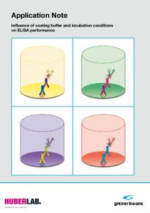
Hardware connection requirements To use the USART bootloader, the host has to be connected to the (RX) and (TX) pins of the desired USARTx interface via a serial cable. Figure 1. USART Connection
ϭ
Zy
h�Zd�,ŽƐƚ
Z
Z
нs
dy
Ϯ
Z^ϮϯϮ� dƌĂŶƐĐĞŝǀĞƌ
dy
Zy
'E�
^dDϯϮ� DŝĐƌŽĐŽŶƚƌŽůůĞƌ
'E� 06Y�����9�
1. A Pull-UP resistor should be added, if pull-up resistor are not connected in host side. 2. An RS232 transceiver must be connected to adapt voltage level (3.3V - 12V) between STM32 device and host.
Note:
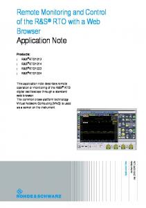
+V typically 3.3 V and R value typically 100KOhm.This value depend on the application and the used hardware. To use the DFU, connect the microcontroller's USB interface to a USB host (i.e. PC).
h^��,ŽƐƚ
нs
ϭ
ϭ͘ϱ
'E�
��E� dƌĂŶƐĐĞŝǀ Ğƌ
dy Zy
^dDϯϮ� DŝĐƌŽĐŽŶƚƌŽůůĞƌ
'E�
06�����9�
Note:
When a bootloader firmware supports DFU, it is mandatory that no USB Host is connected to the USB peripheral during the selection phase of the other interfaces. After selection phase, the user can plug a USB cable without impacting the selected bootloader execution except commands which generate a system reset. It is recommended to keep the RX pins of unused Bootloader interfaces (USART_RX, SPI_MOSI, CAN_RX and USB D+/D- lines if present) at a known (low or high) level at the startup of the Bootloader (detection phase). Leaving these pins floating during the detection phase might lead to activating unused interface.
3.4
Bootloader Memory Management All write operations using bootloader commands must only be Word-aligned (the address should be a multiple of 4). The number of data to be written must also be a multiple of 4 (non-aligned half page write addresses are accepted). Some Products embed bootloader that has some specific features: •
Some products don’t support Mass erase operation. To perform a mass erase operation using bootloader, two options are available: –
Erase all sectors one by one using the Erase command
–
Set protection level to Level 1. Then, set it to Level 0 (using the Read protect command and then the Read Unprotect command). This operation results in a mass erase of the internal Flash memory.
•
Bootloader firmware of STM32 L1 and L0 series supports Data Memory in addition to standard memories (internal Flash, internal SRAM, option bytes and System memory). The start address and the size of this area depends on product, please refer to product reference manual for more information. Data memory can be read and written but cannot be erased using the Erase Command. When writing in a Data memory location, the bootloader firmware manages the erase operation of this location before any write. A write to Data memory must be Word-aligned (address to be written should be a multiple of 4) and the number of data must also be a multiple of 4. To erase a Data memory location, you can write zeros at this location.
•
Bootloader firmware of STM32 F2, F4, F7 and L4 series supports OTP memory in addition to standard memories (internal Flash, internal SRAM, option bytes and System memory). The start address and the size of this area depends on product, please refer to product reference manual for more information. OTP memory can be read and
DocID13801 Rev 31
29/283 282
General bootloader description
AN2606
written but cannot be erased using Erase command. When writing in an OTP memory location, make sure that the relative protection bit is not reset. •
For STM32 F2, F4 and F7 series the internal flash write operation format depends on voltage Range. By default write operation are allowed by one byte format (Half-Word, Word and Double-Word operations are not allowed). to increase the speed of write operation, the user should apply the adequate voltage range that allows write operation by Half-Word, Word or Double-Word and update this configuration on the fly by the bootloader software through a virtual memory location. This memory location is not physical but can be read and written using usual bootloader read/write operations according to the protocol in use. This memory location contains 4 bytes which are described in table below. It can be accessed by 1, 2, 3 or 4 bytes. However, reserved bytes should remain at their default values (0xFF), otherwise the request will be NACKed. Table 4. STM32 F2, F4 and F7 Voltage Range configuration using bootloader Address
Size
Description
0xFFFF0000
1 byte
This byte controls the current value of the voltage range. 0x00: voltage range [1.8 V, 2.1 V] 0x01: voltage range [2.1 V, 2.4 V] 0x02: voltage range [2.4 V, 2.7 V] 0x03: voltage range [2.7 V, 3.6 V] 0x04: voltage range [2.7 V, 3.6 V] and double word write/erase operation is used. In this case it is mandatory to supply 9 V through the VPP pin (refer to the product reference manual for more details about the double-word write procedure). Other: all other values are not supported and will be NACKed.
0xFFFF0001
1 byte
Reserved. 0xFF: default value. Other: all other values are not supported and will be NACKed.
0xFFFF0002
1 byte
Reserved. 0xFF: default value. Other: all other values are not supported and will be NACKed.
0xFFFF0003
1 byte
Reserved. 0xFF: default value. Other: all other values are not supported and will be NACKed.
The table below lists the valid memory area depending on the Bootloader commands. Table 5. Supported memory area by Write, Read, Erase and Go Commands
30/283
Memory Area
Write command
Read command
Erase command
Go command
Flash
Supported
Supported
Supported
Supported
RAM
Supported
Supported
Not supported
Supported
System Memory
Not supported
Supported
Not supported
Not supported
Data Memory
Supported
Supported
Not supported
Not supported
OTP Memory
Supported
Supported
Not supported
Not supported
DocID13801 Rev 31
AN2606
STM32F03xx4/6 devices bootloader
4
STM32F03xx4/6 devices bootloader
4.1
Bootloader configuration The STM32F03xx4/6 bootloader is activated by applying pattern2 (described in Table 2: Bootloader activation patterns). The following table shows the hardware resources used by this bootloader. Table 6. STM32F03xx4/6 configuration in system memory boot mode Bootloader
Feature/Peripheral
State
Comment
RCC
HSI Enabled
The system clock frequency is 24 MHz (using PLL clocked by HSI). 1 Flash Wait State.
RAM
-
2 Kbyte starting from address 0x20000000 are used by the bootloader firmware.
System memory
-
3 Kbyte starting from address 0x1FFFEC00 contain the bootloader firmware.
IWDG
-
The independent watchdog (IWDG) prescaler is configured to its maximum value. It is periodically refreshed to prevent watchdog reset in case the hardware IWDG option was previously enabled by the user.
USART1 bootloader (on PA10/PA9)
USART1
Enabled
Once initialized, the USART1 configuration is 8 bits, even parity and 1 Stop bit.
USART1_RX pin
Input
PA10 pin: USART1 in reception mode.
USART1_TX pin
Output
PA9 pin: USART1 in transmission mode.
USART1 bootloader (on PA14/PA15)
USART1
Enabled
Once initialized, the USART1 configuration is 8 bits, even parity and 1 Stop bit.
USART1_RX pin
Input
PA15 pin: USART1 in reception mode.
USART1_TX pin
Output
PA14 pin: USART1 in transmission mode.
SysTick timer
Enabled
Used to automatically detect the serial baud rate from the host.
Common to all bootloaders
USART1 bootloaders
The system clock is derived from the embedded internal high-speed RC, no external quartz is required for the bootloader execution. Note:
After the STM32F03xx4/6 devices has booted in bootloader mode, serial wire debug (SWD) communication is no longer possible until the system is reset. This is because the SWD uses the PA14 pin (SWCLK) which is already used by the bootloader (USART1_TX).
DocID13801 Rev 31
31/283 282
STM32F03xx4/6 devices bootloader
4.2
AN2606
Bootloader selection The figure below shows the bootloader selection mechanism. Figure 6. Bootloader selection for STM32F03xx4/6 devices
6\VWHP�5HVHW
6\VWHP�,QLW��&ORFN��*3,2V�� ,:'*��6\V7LFN
�[�)�UHFHLYHG�RQ� 86$57[
QR \HV 'LVDEOH�DOO� LQWHUUXSW�VRXUFHV &RQILJXUH� 86$57[ ([HFXWH� %/B86$57B/RRS� IRU�86$57[ 06�����9�
4.3
Bootloader version The following table lists the STM32F03xx4/6 devices bootloader versions. Table 7. STM32F03xx4/6 bootloader versions Bootloader version number
V1.0
32/283
Description
Initial bootloader version
DocID13801 Rev 31
Known limitations For the USART interface, two consecutive NACKs instead of 1 NACK are sent when a Read Memory or Write Memory command is sent and the RDP level is active.
AN2606
STM32F030xC devices bootloader
5
STM32F030xC devices bootloader
5.1
Bootloader configuration The STM32F030xC bootloader is activated by applying pattern2 (described in Table 2: Bootloader activation patterns). The following table shows the hardware resources used by this bootloader. Table 8.STM32F030xC configuration in system memory boot mode Bootloader
Common to all bootloaders
USART1 bootloader
USART2 bootloader
USARTx bootloaders
Feature/Peripheral
State
RCC
HSI enabled
The system clock frequency is 48 MHz with HSI 8 MHz as clock source.
RAM
-
6 Kbyte starting from address 0x20000000 are used by the bootloader firmware
System memory
-
8 Kbyte starting from address 0x1FFFD800, contain the bootloader firmware.
USART1
Enabled
Once initialized the USART1 configuration is: 8-bits, even parity and 1 Stop bit
USART1_RX pin
Input
PA10 pin: USART1 in reception mode
USART1_TX pin
Output
PA9 pin: USART1 in transmission mode
USART2
Enabled
Once initialized the USART2 configuration is: 8-bits, even parity and 1 Stop bit
USART2_RX pin
Input
PA15 pin: USART2 in reception mode
USART2_TX pin
Output
PA14 pin: USART2 in transmission mode
SysTick timer
Enabled
Used to automatically detect the serial baud rate from the host for USARTx bootloaders.
I2C1
Enabled
The I2C1 configuration is: I2C speed: up to 400 KHz, 7-bit address, slave mode, analog filter ON. Slave 7-bit address: 0b1000001x (where x = 0 for write and x = 1 for read)
I2C1_SCL pin
Input/Output
PB6 pin: clock line is used in open-drain mode.
I2C1_SDA pin
Input/Output
PB7 pin: data line is used in open-drain mode.
I2C1 bootloader
Note:
Comment
After the STM32F030xC devices have booted in Bootloader mode using USART2, the serial wire debug (SWD) communication is no more possible until the system is reset, because SWD uses PA14 pin (SWCLK) which is already used by the Bootloader (USART2_RX). The system clock is derived from the embedded internal high-speed RC, no external quartz is required for the bootloader execution.
DocID13801 Rev 31
33/283 282
STM32F030xC devices bootloader
5.2
AN2606
Bootloader selection The figure below shows the bootloader selection mechanism. Figure 7.Bootloader selection for STM32F030xC 6\VWHP�5HVHW
6\VWHP�,QLW��&ORFN��*3,2V�� ,:'*��6\V7LFN
&RQILJXUH�,�&[ \HV �[�)�UHFHLYHG�RQ� 86$57[
'LVDEOH�DOO�LQWHUUXSW� VRXUFHV�DQG�RWKHU� LQWHUIDFHV�FORFN¶V
\HV QR
,�&[�$GGUHVV�� 'HWHFWHG QR
'LVDEOH�DOO�LQWHUUXSW� VRXUFHV�DQG�RWKHU� LQWHUIDFHV�FORFN¶V
&RQILJXUH� 86$57[
([HFXWH� %/B,�&B/RRS�IRU� ,�&[
([HFXWH� %/B86$57B/RRS� IRU�86$57[
06Y�����9�
5.3
Bootloader version The following table lists the STM32F030xC devices bootloader versions. Table 9.STM32F030xC bootloader versions
34/283
Bootloader version number
Description
Known limitations
V5.2
Initial bootloader version
None
DocID13801 Rev 31
AN2606
STM32F05xxx and STM32F030x8 devices bootloader
6
STM32F05xxx and STM32F030x8 devices bootloader
6.1
Bootloader configuration The STM32F05xxx and STM32F030x8 devices bootloader is activated by applying pattern2 (described in Table 2: Bootloader activation patterns). The following table shows the hardware resources used by this bootloader.
Table 10. STM32F05xxx and STM32F030x8 devices configuration in system memory boot mode Bootloader
Common to all bootloaders
USART1 bootloader
USART2 bootloader
USARTx bootloaders
Feature/Peripheral
State
Comment
RCC
HSI Enabled
The system clock frequency is 24 MHz (using PLL clocked by HSI). 1 Flash Wait State.
RAM
-
2 Kbyte starting from address 0x20000000 are used by the bootloader firmware.
System memory
-
3 Kbyte starting from address 0x1FFFEC00, contain the bootloader firmware.
IWDG
-
The independent watchdog (IWDG) prescaler is configured to its maximum value. It is periodically refreshed to prevent watchdog reset in case the hardware IWDG option was previously enabled by the user.
USART1
Enabled
Once initialized, the USART1 configuration is 8 bits, even parity and 1 Stop bit.
USART1_RX pin
Input
PA10 pin: USART1 in reception mode.
USART1_TX pin
Output
PA9 pin: USART1 in transmission mode.
USART2
Enabled
Once initialized, the USART2 configuration is 8 bits, even parity and 1 Stop bit.
USART2_RX pin
Input
PA15 pin: USART2 in reception mode.
USART2_TX pin
Output
PA14 pin: USART2 in transmission mode.
SysTick timer
Enabled
Used to automatically detect the serial baud rate from the host.
The system clock is derived from the embedded internal high-speed RC, no external quartz is required for the bootloader execution. Note:
After the STM32F05xxx and STM32F030x8 devices have booted in bootloader mode, the serial wire debug (SWD) communication is no more possible until the system is reset, because SWD uses PA14 pin (SWCLK) which is already used by the bootloader (USART2_TX).
DocID13801 Rev 31
35/283 282
STM32F05xxx and STM32F030x8 devices bootloader
6.2
AN2606
Bootloader selection The figure below shows the bootloader selection mechanism. Figure 8. Bootloader selection for STM32F05xxx and STM32F030x8 devices 6\VWHP�5HVHW
6\VWHP�,QLW��&ORFN��*3,2V�� ,:'*��6\V7LFN
�[�)�UHFHLYHG�RQ� 86$57[
QR \HV 'LVDEOH�DOO� LQWHUUXSW�VRXUFHV &RQILJXUH� 86$57[ ([HFXWH� %/B86$57B/RRS� IRU�86$57[ 06�����9�
6.3
Bootloader version The following table lists the STM32F05xxx and STM32F030x8 devices bootloader versions. Table 11. STM32F05xxx and STM32F030x8 devices bootloader versions Bootloader version number
V2.1
36/283
Description
Known limitations
Initial bootloader version
– At bootloader startup, the HSITRIM value is set to (0) (in HSITRIM bits on RCC_CR register) instead of default value (16), as consequence a deviation is generated in crystal measurement. For better results, please use the smallest supported crystal value (ie. 4 MHz). – For the USART interface, two consecutive NACKs instead of 1 NACK are sent when a Read Memory or Write Memory command is sent and the RDP level is active.
DocID13801 Rev 31
AN2606
STM32F04xxx devices bootloader
7
STM32F04xxx devices bootloader
7.1
Bootloader configuration The STM32F04xxx bootloader is activated by applying pattern6 (described in Table 2: Bootloader activation patterns). The following table shows the hardware resources used by this bootloader. Table 12. STM32F04xxx configuration in system memory boot mode Bootloader
Feature/Peripheral
State HSI enabled
The system clock frequency is 48 MHz with HSI48 48 MHz as clock source.
-
The Clock Recovery System (CRS) is enabled for the DFU bootloader to allow USB to be clocked by HSI48 48 MHz.
RAM
-
6 Kbyte starting from address 0x20000000 are used by the bootloader firmware
System memory
-
13 Kbyte starting from address 0x1FFFC400, contain the bootloader firmware
IWDG
-
The independent watchdog (IWDG) prescaler is configured to its maximum value. It is periodically refreshed to prevent watchdog reset (in case the hardware IWDG option was previously enabled by the user).
USART1
Enabled
Once initialized the USART1 configuration is: 8-bits, even parity and 1 Stop bit
USART1_RX pin
Input
PA10 pin: USART1 in reception mode
USART1_TX pin
Output
PA9 pin: USART1 in transmission mode
USART2
Enabled
Once initialized the USART2 configuration is: 8-bits, even parity and 1 Stop bit
USART2_RX pin
Input
PA15 pin: USART2 in reception mode
USART2_TX pin
Output
PA14 pin: USART2 in transmission mode
SysTick timer
Enabled
Used to automatically detect the serial baud rate from the host for USARTx bootloaders.
I2C1
Enabled
The I2C1configuration is: I2C speed: up to 400 KHz, 7-bit address, slave mode, analog filter ON. Slave 7-bit address: 0b0111110x (where x = 0 for write and x = 1 for read).
I2C1_SCL pin
Input/Output
PB6 pin: clock line is used in open-drain mode.
I2C1_SDA pin
Input/Output
PB7 pin: data line is used in open-drain mode.
RCC
Common to all bootloaders
USART1 bootloader
USART2 bootloader
USARTx bootloaders
Comment
I2C1 bootloader
DocID13801 Rev 31
37/283 282
STM32F04xxx devices bootloader
AN2606
Table 12. STM32F04xxx configuration in system memory boot mode (continued) Bootloader
Feature/Peripheral USB
DFU bootloader
Enabled
USB_DM pin USB_DP pin
Note:
State
Comment USB used in FS mode PA11: USB DM line.
Input/Output
PA12: USB DP line No external pull-up resistor is required.
After the STM32F04xxx devices have booted in Bootloader mode using USART2, the serial wire debug (SWD) communication is no more possible until the system is reset, because SWD uses PA14 pin (SWCLK) which is already used by the Bootloader (USART2_RX). The system clock is derived from the embedded internal high-speed RC, no external quartz is required for the bootloader execution.
Note:
38/283
User can jump to the System Memory Bootloader from his application code using the following entry point:0x1FFFC519 (Thumb mode).
DocID13801 Rev 31
AN2606
7.2
STM32F04xxx devices bootloader
Bootloader selection The figure below shows the bootloader selection mechanism. Figure 9. Bootloader selection for STM32F04xxx 6\VWHP�5HVHW
6\VWHP�,QLW��&ORFN��*3,2V�� ,:'*��6\V7LFN
�ŽŶĨŝŐƵƌĞ�/Ϯ�dž
�ŽŶĨŝŐƵƌĞ�h^��&^�ĚĞǀŝĐĞ
�[�)�UHFHLYHG� RQ�86$57[
LJĞƐ LJĞƐ
QR ,�&[�$GGUHVV�� 'HWHFWHG
ŶŽ
QR 86%�� 'HWHFWHG
'LVDEOH�DOO�LQWHUUXSW� VRXUFHV�DQG�RWKHU� LQWHUIDFHV�FORFN¶V
\HV
�ŝƐĂďůĞ�ŽƚŚĞƌ� ŝŶƚĞƌĨĂĐĞƐ�ĐůŽĐŬ͛Ɛ
([HFXWH�')8� ERRWORDGHU�XVLQJ�86%� LQWHUUXSWV
([HFXWH� %/B,�&B/RRS�IRU� ,�&[
�ŝƐĂďůĞ�Ăůů�ŝŶƚĞƌƌƵƉƚ� ƐŽƵƌĐĞƐ�ĂŶĚ�ŽƚŚĞƌ� ŝŶƚĞƌĨĂĐĞƐ�ĐůŽĐŬ͛Ɛ &RQILJXUH� 86$57[
([HFXWH� %/B86$57B/RRS� IRU�86$57[
06�����9�
DocID13801 Rev 31
39/283 282
STM32F04xxx devices bootloader
7.3
AN2606
Bootloader version The following table lists the STM32F04xxx devices bootloader versions: Table 13. STM32F04xxx bootloader versions Bootloader version number
40/283
Description
V10.0
Initial bootloader version
V10.1
Add dynamic support of USART/USB interfaces on PA11/12 IOs for small packages.
Known limitations At bootloader startup, the HSITRIM value is set to (0) (in HSITRIM bits on RCC_CR register) instead of default value (16), as consequence a deviation is generated in crystal measurement. For better results, please use the smallest supported crystal value (ie. 4 MHz).
DocID13801 Rev 31
AN2606
STM32F070x6 devices bootloader
8
STM32F070x6 devices bootloader
8.1
Bootloader configuration The STM32F070x6 bootloader is activated by applying pattern6 (described in Table 2: Bootloader activation patterns). The following table shows the hardware resources used by this bootloader. Table 14. STM32F070x6 configuration in system memory boot mode Bootloader
Feature/Periphe ral
At startup, the system clock frequency is configured to 48 MHz using the HSI. If an external clock (HSE) is not present, the system is kept clocked from the HSI.
HSE enabled
The external clock can be used for all bootloader interfaces and should have one of the following values [24, 18, 16, 12, 8, 6, 4] MHz. The PLL is used to generate 48 MHz for USB and system clock.
-
The Clock Security System (CSS) interrupt is enabled for HSE. Any failure (or removal) of the external clock generates system reset.
RAM
-
6 Kbyte starting from address 0x20000000 are used by the bootloader firmware
System memory
-
13 Kbyte starting from address 0x1FFFC400, contain the bootloader firmware.
USART1
Enabled
Once initialized the USART1 configuration is: 8-bits, even parity and 1 Stop bit
USART1_RX pin
Input
PA10 pin: USART1 in reception mode
USART1_TX pin
Output
PA9 pin: USART1 in transmission mode
USART2
Enabled
Once initialized the USART2 configuration is: 8-bits, even parity and 1 Stop bit
USART2_RX pin
Input
PA15 pin: USART2 in reception mode
USART2_TX pin
Output
PA14 pin: USART2 in transmission mode
SysTick timer
Enabled
Used to automatically detect the serial baud rate from the host for USARTx bootloaders.
Enabled
The I2C1 configuration is: I2C speed: up to 400 KHz, 7-bit address, slave mode, analog filter ON. Slave 7-bit address: 0b0111110x where x = 0 for write and x = 1 for read)
I2C1_SCL pin
Input/Output
PB6 pin: clock line is used in open-drain mode.
I2C1_SDA pin
Input/Output
PB7 pin: data line is used in open-drain mode.
Common to all bootloaders
USART2 bootloader
USARTx bootloaders
Comment
HSI enabled
RCC
USART1 bootloader
State
I2C1 I2C1 bootloader
DocID13801 Rev 31
41/283 282
STM32F070x6 devices bootloader
AN2606
Table 14. STM32F070x6 configuration in system memory boot mode (continued) Bootloader
Feature/Periphe ral USB
DFU bootloader
State
Enabled
USB_DM pin USB_DP pin
Comment USB FS configured in Forced Device mode. USB FS interrupt vector is enabled and used for USB DFU communications. PA11 pin: USB FS DM line
Input/Output
PA12 pin: USB FS DP line. No external Pull-up resistor is required.
Note:
If HSI deviation exceeds 1% , the bootloader might not function correctly.
Note:
After the STM32F070x6 devices have booted in Bootloader mode using USART2, the serial wire debug (SWD) communication is no more possible until the system is reset, because SWD uses PA14 pin (SWCLK) which is already used by the Bootloader (USART2_RX). The bootloader has two cases of operation depending on the presence of the external clock (HSE) at bootloader startup: •
If HSE is present and has a value of 24, 18, 16, 12, 8, 6, 4 MHz, the system clock is configured to 48 MHz with HSE as clock source. The DFU interface, USART1, USART2 and I2C1 are functional and can be used to communicate with the bootloader device.
•
If HSE is not present, the HSI is kept as default clock source and only USART1, USART2 and I2C1 are functional.
The external clock (HSE) must be kept if it’s connected at bootloader startup because it will be used as system clock source. Note:
42/283
User can jump to the System Memory Bootloader from his application code using the following entry point: 0x1FFFC519 (Thumb mode).
DocID13801 Rev 31
AN2606
8.2
STM32F070x6 devices bootloader
Bootloader selection The figure below shows the bootloader selection mechanism. Figure 10.Bootloader selection for STM32F070x6 6\VWHP�5HVHW
&RQILJXUH�6\VWHP�FORFN�WR� ���0+]�XVLQJ�+6,
+6( ������������� ������������0+]�"
QR
LJĞƐ 5HFRQILJXUH�6\VWHP�FORFN�WR� ���0+]�XVLQJ�+6( 6\VWHP�,QLW��&ORFN��*3,2V�� ,:'*��6\V7LFN
6\VWHP�,QLW��&ORFN��*3,2V�� ,:'*��6\V7LFN
&RQILJXUH�86%��
&RQILJXUH�,�&[
�[�)�UHFHLYHG �RQ�86$57[
\HV
\HV
QR
,�&[�$GGUHVV�� 'HWHFWHG
QR
'LVDEOH�DOO�LQWHUUXSW� VRXUFHV�DQG�RWKHU� LQWHUIDFHV�FORFN¶V \HV 'LVDEOH�RWKHU� LQWHUIDFHV�FORFN¶V
'LVDEOH�DOO�LQWHUUXSW� VRXUFHV�DQG�RWKHU� LQWHUIDFHV�FORFN¶V
&RQILJXUH� 86$57[
([HFXWH�')8� ERRWORDGHU�XVLQJ�86%� LQWHUUXSWV
([HFXWH� %/B,�&B/RRS�IRU� ,�&[
([HFXWH� %/B86$57B/RRS� IRU�86$57[
QR 86%�FDEOH� 'HWHFWHG� �86%� FRQILJXUHG
06Y�����9�
DocID13801 Rev 31
43/283 282
STM32F070x6 devices bootloader
8.3
AN2606
Bootloader version The following table lists the STM32F070x6 devices bootloader versions. Table 15.STM32F070x6 bootloader versions
44/283
Bootloader version number
Description
Known limitations
V10.2
Initial bootloader version
V10.3
Clock configuration fixed to HSI 8 MHz
At bootloader startup, the HSITRIM value is set to (0) (in HSITRIM bits on RCC_CR register) instead of default value (16), as consequence a deviation is generated in crystal measurement. For better results, please use the smallest supported crystal value (ie. 4 MHz).
DocID13801 Rev 31
AN2606
STM32F070xB devices bootloader
9
STM32F070xB devices bootloader
9.1
Bootloader configuration The STM32F070xB bootloader is activated by applying pattern2 (described in Table 2: Bootloader activation patterns). The following table shows the hardware resources used by this bootloader. Table 16. STM32F070xB configuration in system memory boot mode Bootloader
Feature/Peripheral
State
HSI enabled
At startup, the system clock frequency is configured to 48 MHz using the HSI. If an external clock (HSE) is not present, the system is kept clocked from the HSI.
HSE enabled
The external clock can be used for all bootloader interfaces and should have one of the following values [24, 18, 16, 12, 8, 6, 4] MHz. The PLL is used to generate 48 MHz for USB and system clock.
-
The Clock Security System (CSS) interrupt is enabled for HSE. Any failure (or removal) of the external clock generates system reset.
RAM
-
6 Kbyte starting from address 0x20000000 are used by the bootloader firmware
System memory
-
12 Kbyte starting from address 0x1FFFC800, contain the bootloader firmware.
USART1
Enabled
Once initialized the USART1 configuration is: 8-bits, even parity and 1 Stop bit
USART1_RX pin
Input
PA10 pin: USART1 in reception mode
USART1_TX pin
Output
PA9 pin: USART1 in transmission mode
USART2
Enabled
Once initialized the USART2 configuration is: 8-bits, even parity and 1 Stop bit
USART2_RX pin
Input
PA15 pin: USART2 in reception mode
USART2_TX pin
Output
PA14 pin: USART2 in transmission mode
SysTick timer
Enabled
Used to automatically detect the serial baud rate from the host for USARTx bootloaders.
I2C1
Enabled
The I2C1 configuration is: I2C speed: up to 400 KHz, 7-bit address, slave mode, analog filter ON. Slave 7-bit address: 0b0111011x (where x = 0 for write and x = 1 for read)
I2C1_SCL pin
Input/Output
PB6 pin: clock line is used in open-drain mode.
I2C1_SDA pin
Input/Output
PB7 pin: data line is used in open-drain mode.
RCC Common to all bootloaders
USART1 bootloader
USART2 bootloader
USARTx bootloaders
Comment
I2C1 bootloader
DocID13801 Rev 31
45/283 282
STM32F070xB devices bootloader
AN2606
Table 16. STM32F070xB configuration in system memory boot mode (continued) Bootloader
Feature/Peripheral USB
DFU bootloader
State Enabled
USB_DM pin USB_DP pin
Comment USB FS configured in Forced Device mode. USB FS interrupt vector is enabled and used for USB DFU communications. PA11 pin: USB FS DM line
Input/Output
PA12 pin: USB FS DP line. No external Pull-up resistor is required.
Note:
If HSI deviation exceeds 1% , the bootloader might not function correctly.
Note:
After the STM32F070xB devices have booted in Bootloader mode using USART2, the serial wire debug (SWD) communication is no more possible until the system is reset, because SWD uses PA14 pin (SWCLK) which is already used by the Bootloader (USART2_RX). The bootloader has two cases of operation depending on the presence of the external clock (HSE) at bootloader startup: •
If HSE is present and has a value of 24, 18, 16, 12, 8, 6, 4 MHz, the system clock is configured to 48 MHz with HSE as clock source. The DFU interface, USART1, USART2 and I2C1 are functional and can be used to communicate with the bootloader device.
•
If HSE is not present, the HSI is kept as default clock source and only USART1, USART2 and I2C1 are functional.
The external clock (HSE) must be kept if it’s connected at bootloader startup because it will be used as system clock source.
46/283
DocID13801 Rev 31
AN2606
9.2
STM32F070xB devices bootloader
Bootloader selection The figure below shows the bootloader selection mechanism. Figure 11.Bootloader selection for STM32F070xB 6\VWHP�5HVHW
&RQILJXUH�6\VWHP�FORFN�WR� ���0+]�XVLQJ�+6,
+6( �������������������� �����0+]�"
QR
LJĞƐ 5HFRQILJXUH�6\VWHP�FORFN�WR� ���0+]�XVLQJ�+6( 6\VWHP�,QLW��&ORFN��*3,2V�� ,:'*��6\V7LFN
6\VWHP�,QLW��&ORFN��*3,2V�� ,:'*��6\V7LFN
&RQILJXUH�86%��
&RQILJXUH�,�&[
�[�)�UHFHLYHG� RQ�86$57[
\HV
\HV
QR
,�&[�$GGUHVV�� 'HWHFWHG
QR
'LVDEOH�DOO�LQWHUUXSW� VRXUFHV�DQG�RWKHU� LQWHUIDFHV�FORFN¶V \HV 'LVDEOH�RWKHU� LQWHUIDFHV�FORFN¶V
'LVDEOH�DOO�LQWHUUXSW� VRXUFHV�DQG�RWKHU� LQWHUIDFHV�FORFN¶V
&RQILJXUH� 86$57[
([HFXWH�')8� ERRWORDGHU�XVLQJ�86%� LQWHUUXSWV
([HFXWH� %/B,�&B/RRS�IRU� ,�&[
([HFXWH� %/B86$57B/RRS� IRU�86$57[
QR 86%�FDEOH� 'HWHFWHG� �86%� FRQILJXUHG
06Y�����9�
DocID13801 Rev 31
47/283 282
STM32F070xB devices bootloader
9.3
AN2606
Bootloader version The following table lists the STM32F070xB devices bootloader versions. Table 17.STM32F070xB bootloader versions
48/283
Bootloader version number
Description
Known limitations
V10.2
Initial bootloader version
V10.3
Clock configuration fixed to HSI 8 MHz
At bootloader startup, the HSITRIM value is set to (0) (in HSITRIM bits on RCC_CR register) instead of default value (16), as consequence a deviation is generated in crystal measurement. For better results, please use the smallest supported crystal value (ie. 4 MHz).
DocID13801 Rev 31
AN2606
STM32F071xx/072xx devices bootloader
10
STM32F071xx/072xx devices bootloader
10.1
Bootloader configuration The STM32F071xx/072xx bootloader is activated by applying pattern2 (described in Table 2: Bootloader activation patterns). The following table shows the hardware resources used by this bootloader. Table 18. STM32F071xx/072xx configuration in system memory boot mode
Bootloader
Feature/Peripheral
State HSI enabled
The system clock frequency is 48 MHz with HSI48 48 MHz as clock source.
-
The Clock Recovery System (CRS) is enabled for the DFU bootloader to allow USB to be clocked by HSI48 48 MHz.
RAM
-
6 Kbyte starting from address 0x20000000 are used by the bootloader firmware
System memory
-
12 Kbyte starting from address 0x1FFFC800, contain the bootloader firmware
IWDG
-
The independent watchdog (IWDG) prescaler is configured to its maximum value. It is periodically refreshed to prevent watchdog reset (in case the hardware IWDG option was previously enabled by the user).
USART1
Enabled
Once initialized the USART1 configuration is: 8-bits, even parity and 1 Stop bit
USART1_RX pin
Input
PA10 pin: USART1 in reception mode
USART1_TX pin
Output
PA9 pin: USART1 in transmission mode
USART2
Enabled
Once initialized the USART2 configuration is: 8-bits, even parity and 1 Stop bit
USART2_RX pin
Input
PA15 pin: USART2 in reception mode
USART2_TX pin
Output
PA14 pin: USART2 in transmission mode
SysTick timer
Enabled
Used to automatically detect the serial baud rate from the host for USARTx bootloaders.
I2C1
Enabled
The I2C1 configuration is: I2C speed: up to 400 KHz, 7-bit address, slave mode, analog filter ON. Slave 7-bit address: 0b0111011x (where x = 0 for write and x = 1 for read)
I2C1_SCL pin
Input/Output
PB6 pin: clock line is used in open-drain mode.
I2C1_SDA pin
Input/Output
PB7 pin: data line is used in open-drain mode.
RCC
Common to all bootloaders
USART1 bootloader
USART2 bootloader
USARTx bootloaders
Comment
I2C1 bootloader
DocID13801 Rev 31
49/283 282
STM32F071xx/072xx devices bootloader
AN2606
Table 18. STM32F071xx/072xx configuration in system memory boot mode (continued) Bootloader
Feature/Peripheral USB
DFU bootloader
Enabled
USB_DM pin USB_DP pin
Note:
State
Comment USB used in FS mode PA11: USB DM line.
Input/Output
PA12: USB DP line No external pull-up resistor is required.
After the STM32F071xx/072xx devices have booted in Bootloader mode using USART2, the serial wire debug (SWD) communication is no more possible until the system is reset, because SWD uses PA14 pin (SWCLK) which is already used by the Bootloader (USART2_RX). The system clock is derived from the embedded internal high-speed RC, no external quartz is required for the bootloader execution.
50/283
DocID13801 Rev 31
AN2606
10.2
STM32F071xx/072xx devices bootloader
Bootloader selection The figure below shows the bootloader selection mechanism. Figure 12. Bootloader selection for STM32F071xx/072xx 6\VWHP�5HVHW
6\VWHP�,QLW��&ORFN��*3,2V�� ,:'*��6\V7LFN
�ŽŶĨŝŐƵƌĞ�/Ϯ�dž
�ŽŶĨŝŐƵƌĞ�h^��&^�ĚĞǀŝĐĞ
�[�)�UHFHLYHG�RQ� 86$57[
LJĞƐ LJĞƐ
QR ,�&[�$GGUHVV�� 'HWHFWHG
ŶŽ
'LVDEOH�DOO�LQWHUUXSW� VRXUFHV�DQG�RWKHU� LQWHUIDFHV�FORFN¶V
LJĞƐ
�ŝƐĂďůĞ�ŽƚŚĞƌ� ŝŶƚĞƌĨĂĐĞƐ�ĐůŽĐŬ͛Ɛ
QR 86%�� 'HWHFWHG
([HFXWH� %/B,�&B/RRS�IRU� ,�&[
([HFXWH�')8� ERRWORDGHU�XVLQJ�86%� LQWHUUXSWV
�ŝƐĂďůĞ�Ăůů�ŝŶƚĞƌƌƵƉƚ� ƐŽƵƌĐĞƐ�ĂŶĚ�ŽƚŚĞƌ� ŝŶƚĞƌĨĂĐĞƐ�ĐůŽĐŬ͛Ɛ &RQILJXUH� 86$57[
([HFXWH� %/B86$57B/RRS� IRU�86$57[
06�����9�
10.3
Bootloader version The following table lists the STM32F071xx/072xx devices bootloader versions: Table 19. STM32F071xx/072xx bootloader versions Bootloader version number
V10.1
Description
Known limitations
Initial bootloader version
At bootloader startup, the HSITRIM value is set to (0) (in HSITRIM bits on RCC_CR register) instead of default value (16), as consequence a deviation is generated in crystal measurement. For better results, please use the smallest supported crystal value (ie. 4 MHz).
DocID13801 Rev 31
51/283 282
STM32F09xxx devices bootloader
AN2606
11
STM32F09xxx devices bootloader
11.1
Bootloader configuration The STM32F09xxx bootloader is activated by applying pattern6 (described in Table 2: Bootloader activation patterns). The following table shows the hardware resources used by this bootloader. Table 20.STM32F09xxx configuration in system memory boot mode
Bootloader
Common to all bootloaders
USART1 bootloader
USART2 bootloader
USARTx bootloaders
Feature/Peripheral
State
RCC
HSI enabled
The system clock frequency is 48 MHz with HSI48 48 MHz as clock source.
RAM
-
6 Kbyte starting from address 0x20000000 are used by the bootloader firmware
System memory
-
8 Kbyte starting from address 0x1FFFD800, contain the bootloader firmware.
USART1
Enabled
Once initialized the USART1 configuration is: 8-bits, even parity and 1 Stop bit
USART1_RX pin
Input
PA10 pin: USART1 in reception mode
USART1_TX pin
Output
PA9 pin: USART1 in transmission mode
USART2
Enabled
Once initialized the USART2 configuration is: 8-bits, even parity and 1 Stop bit
USART2_RX pin
Input
PA15 pin: USART2 in reception mode
USART2_TX pin
Output
PA14 pin: USART2 in transmission mode
SysTick timer
Enabled
Used to automatically detect the serial baud rate from the host for USARTx bootloaders.
I2C1
Enabled
The I2C1 configuration is: I2C speed: up to 400 KHz, 7-bit address, slave mode, analog filter ON. Slave 7-bit address: 0b1000001x (where x = 0 for write and x = 1 for read)
I2C1_SCL pin
Input/Output
PB6 pin: clock line is used in open-drain mode.
I2C1_SDA pin
Input/Output
PB7 pin: data line is used in open-drain mode.
I2C1 bootloader
Note:
Comment
After the STM32F09xxx devices have booted in Bootloader mode using USART2, the serial wire debug (SWD) communication is no more possible until the system is reset, because SWD uses PA14 pin (SWCLK) which is already used by the Bootloader (USART2_RX). The system clock is derived from the embedded internal high-speed RC, no external quartz is required for the bootloader execution.
52/283
DocID13801 Rev 31
AN2606
11.2
STM32F09xxx devices bootloader
Bootloader selection The figure below shows the bootloader selection mechanism. Figure 13. Bootloader selection for STM32F09xxx 6\VWHP�5HVHW
6\VWHP�,QLW��&ORFN��*3,2V�� ,:'*��6\V7LFN
&RQILJXUH�,�&[ \HV �[�)�UHFHLYHG�RQ� 86$57[
'LVDEOH�DOO�LQWHUUXSW� VRXUFHV�DQG�RWKHU� LQWHUIDFHV�FORFN¶V
\HV QR
,�&[�$GGUHVV�� 'HWHFWHG QR
'LVDEOH�DOO�LQWHUUXSW� VRXUFHV�DQG�RWKHU� LQWHUIDFHV�FORFN¶V
&RQILJXUH� 86$57[
([HFXWH� %/B,�&B/RRS�IRU� ,�&[
([HFXWH� %/B86$57B/RRS� IRU�86$57[
06Y�����9�
11.3
Bootloader version The following table lists the STM32F09xxx devices bootloader versions. Table 21.STM32F09xxx bootloader versions Bootloader version number
V5.0
Description
Known limitations
Initial bootloader version
At bootloader startup, the HSITRIM value is set to (0) (in HSITRIM bits on RCC_CR register) instead of default value (16), as consequence a deviation is generated in crystal measurement. For better results, please use the smallest supported crystal value (ie. 4 MHz).
DocID13801 Rev 31
53/283 282
STM32F10xxx devices bootloader
AN2606
12
STM32F10xxx devices bootloader
12.1
Bootloader configuration The STM32F10xxx bootloader is activated by applying pattern1 (described in Table 2: Bootloader activation patterns). The following table shows the hardware resources used by this bootloader. Table 22. STM32F10xxx configuration in system memory boot mode
Bootloader
USART1 bootloader
Feature/Peripheral
State
Comment
RCC
HSI enabled
The system clock frequency is 24 MHz using the PLL.
RAM
-
512 byte starting from address 0x20000000 are used by the bootloader firmware.
System memory
-
2 Kbyte starting from address 0x1FFFF000 contain the bootloader firmware.
IWDG
-
The independent watchdog (IWDG) prescaler is configured to its maximum value and is periodically refreshed to prevent watchdog reset (in case the hardware IWDG option was previously enabled by the user).
USART1
Enabled
Once initialized, the USART1 configuration is: 8 bits, even parity and 1 Stop bit.
USART1_RX pin
Input
PA10 pin: USART1 in reception mode
USART1_TX pin
Output push-pull
PA9 pin: USART1 in transmission mode
SysTick timer
Enabled
Used to automatically detect the serial baud rate from the host.
The system clock is derived from the embedded internal high-speed RC, no external quartz is required for the bootloader execution.
54/283
DocID13801 Rev 31
AN2606
12.2
STM32F10xxx devices bootloader
Bootloader selection The figure below shows the bootloader selection mechanism. Figure 14. Bootloader selection for STM32F10xxx 6\VWHP�5HVHW
6\VWHP�,QLW��&ORFN��*3,2V�� ,:'*��6\V7LFN
�[�)�UHFHLYHG�RQ� 86$57[
1R