Oct 11, 2010 - by a transverse domain wall. However, the angular de- pendence of the coercivity in magnetic nanowire arrays has not been modeled yet. Thus ...
Angular dependence of magnetic properties in Ni nanowire arrays R. Lav´ın1,2,3, J. C. Denardin1,3 , J. Escrig1,3, D. Altbir1,3 , A. Cort´es4, and H. G´omez5 1
arXiv:1010.2264v1 [cond-mat.mes-hall] 11 Oct 2010
5
Departamento de F´ısica, Universidad de Santiago de Chile, USACH, Av. Ecuador 3493, Santiago, Chile 2 Facultad de Ingenier´ıa, Universidad Diego Portales, Ej´ercito 441, Santiago, Chile 3 Centro para el Desarrollo de la Nanociencia y Nanotecnolog´ıa, CEDENNA 4 Departamento de F´ısica, Universidad T´ecnica Federico Santa Mar´ıa, Av. Espa˜ na 1680, Casilla 110 V, Valpara´ıso, Chile Instituto de Qu´ımica, Facultad de Ciencias, Universidad Cat´ olica de Valpara´ıso, Casilla 4059, Valpara´ıso, Chile The angular dependence of the remanence and coercivity of Ni nanowire arrays produced inside the pores of anodic alumina membranes has been studied. By comparing our analytical calculations with our measurements we conclude that the magnetization reversal in this array is driven by means of the nucleation and propagation of a transverse wall. A simple model based on an adapted StonerWohlfarth model is used to explain the angular dependence of the coercivity. PACS numbers: 75.75.+a,75.10.-b,75.60.Jk
I.
INTRODUCTION
Arrays of magnetic nanowires have attracted considerable interest due to their promising technological applications [1–4] mainly in high-density information storage. Electrodeposition in polycarbonate and alumina membranes is the preferred technique used in the fabrication of these systems [5, 6], leading to the production of highly ordered arrays of magnetic nanowires inside the pores of membranes [6–10]. Different groups have investigated the role of magnetostatic interactions and the influence of the size of nanowires on the magnetic properties of these systems [11–14]. Recently Escrig et al [11] investigated the dependence of the coercivity of Ni nanowire arrays when the external magnetic field is applied parallel to the nanowire axis. However, for applications in devices that use longitudinal/perpendicular magnetic recording, it is important to investigate the angular dependence of the magnetization. It is expected that the direction of the external magnetic field with respect to the wire axis strongly influences the magnetic properties of the array. The properties of virtually all magnetic materials are controlled by domains separated by domain walls. Measurements on elongated magnetic nanostructures[15] highlighted the importance of nucleation and propagation of a domain wall between opposing magnetic domains in the magnetization reversal process. Three main idealized modes of magnetization reversal have been identified and occur depending on the geometry of the particles [12, 16, 17]. These mechanisms are known as coherent rotation, C, with all the spins rotating simultaneously; vortex wall, V, in which spins invert progressively via propagation of a vortex domain wall; and transverse wall, T, in which spins invert progressively via propagation of a transverse domain wall. If a wire is thin enough, the exchange interaction forces the magnetization to be homogeneous through any radial cross section of the particle [18]. In this way a transverse wall is the preferred mode in thin ferromagnetic wires (diameters d < 60 nm). To investigate the angular dependence of the reversal of the magnetization in nanoparticles, several models
have been proposed. In particular, the Stoner-Wohlfarth model has been used to calculate the angular dependence of the coercivity when the reversal of the magnetization is driven by coherent rotation [19]. However, Landeros et al [17] have shown that coherent rotation is present only in very short particles, namely, when the length of the particles is similar to the domain wall width. On the other side, Aharoni [20] calculated the angular dependence of the nucleation field in an ellipsoid when the reversal is driven by curling rotation. Escrig et al [21] extended this expression for magnetic nanotubes. Finally, Allende et al [22] presented an expression for the angular dependence of the coercivity in magnetic nanotubes when the reversal of the magnetization is driven by a transverse domain wall. However, the angular dependence of the coercivity in magnetic nanowire arrays has not been modeled yet. Thus, usually experimental results for the angular dependence of the coercivity are interpreted using the Stoner-Wohlfarth model [19]. In this paper we present an analytical model that allows us to investigate the angular dependence of the coercivity and remanence for Ni nanowire arrays, considering the different modes that can be present, as a function of wire geometry. Additionally, experimental data for the switching field of high-aspect ratio Ni nanowires will be compared with this analytical model.
II.
EXPERIMENTAL METHODS
Our approach to the preparation of magnetic Ni nanowires arranged in hexagonally ordered, parallel arrays is based on the combination of two complementary aspects, namely, (i) the use of self-ordered anodic aluminum oxide (AAO) as a porous template and (ii) the electrodeposition of Ni in the cylindrical pores. Anodic aluminum oxide is obtained from the electrochemical oxidation of aluminum metal under high voltage (usually 20-200 V) in aqueous acidic solutions [6]. Under certain proper sets of experimental conditions (acid nature and concentration, temperature, and ap-
2
III.
ANALYTICAL MODEL
In order to analyze our results for the angular dependence, we made calculations which lead us to obtain analytical expressions for both coercivity and remanence.
1.0
a
( )
M / M
0
0.5
0.0
L = 4
-0.5
µm H
parallel
H
perpendicular
-1.0 1.0
b
( )
0
0.5
M / M
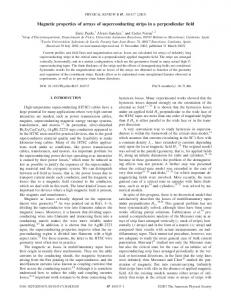
plied voltage), the electrochemically generated layer of alumina displays a self-ordered porous structure. Cylindrical pores of homogeneous diameter are thus obtained, with their long axis perpendicular to the plane of the alumina layer and ordered in a close-packed hexagonal arrangement. With our method [23], first and second anodizations of Al have been carried out in 0.3M oxalic acid under 40 V at 20 o C. Subsequently, the pores were widened in a 0.085M H3 PO4 solution at 37 o C, obtaining pores of d = 2R = 50 nm diameter and a center-to-center distance of D = 100 nm. Electrodeposition was performed at a constant potential (dc electrodeposition at -1.0 V). To facilitate the electric contact, a very thin Au-Pd layer was sputtered on one side of the membrane, followed by the electrodeposition [11, 24] of a thicker nickel layer to achieve full pore sealing. The potentiostatic condition allows us to have more precise control of the electrochemical reaction, and then more accurate control of the growth of the Ni nanowires [11]. The morphology and the single-crystal structure of the individual nanowires after dissolution of the template were subsequently investigated by scanning electron microscopy (SEM) and transmission electron microscopy (TEM) using a JEOL 5900 LV, checking the high ordering of the hexagonal arrays and the large aspect ratio. [11] The chemical characterization of the nanowires was made by means of energy dispersive analysis of Xrays (EDAX), obtaining a clear peak corresponding to the emission spectrum of Ni. [11] The magnetic measurements were performed by a vibrating sample magnetometer (VSM) with the applied field at different angles. The measurements were made at ambient temperature. Figure 1 illustrates the hysteresis curves for two samples with diameter d = 50 nm, lattice parameter D = 100 nm, and lengths (a) L = 4 µm and (b) 12 µm, measured with the external field along and perpendicular to the axis of the wires. In this figure it is clearly seen that the easy axis of the nanowires is along the wire axis. In a series of Ni nanowire arrays of varying lengths (all other geometric parameters being kept constant) investigated by VSM magnetometry, we observed a significant dependence of the remanence (see Fig. 2) and coercivity (see Fig. 3) on the angle at which the external magnetic field is applied. In particular, the coercive field Hc can be tuned between 100 and 720 Oe approximately by properly adjusting θ. The 12 µm nanowires present a sharp decrease of the coercivity and remanence near 90◦ , while the 4 µm sample has a broader curve.
0.0
L = 12
-0.5
µm
H
parallel
H
perpendicular
-1.0 -4
-2
0
2
4
Applied field H / kOe
FIG. 1: Hysteresis curves at external field parallel and perpendicular to the nanowire axis, for two arrays with (a) L = 4 µm and (b) 12 µm, d = 50 nm, and D = 100 nm.
A.
Angular dependence of the remanence
In an array the magnetization inside each nanowire is oriented parallel to the wire’s axis (easy axis), due to the strong shape anisotropy. When the applied field is reduced to zero, at remanence, each wire presents its magnetization along the axis, but it is measured at an angle θ with respect to the easy axis. When the field is reduced to zero, and due to the strong shape anisotropy, the remanence rapidly relaxes and points along the axis. Then, one can approximate the remanence of the wire by the projection of the magnetization on the direction of measurement, i. e., MR (θ) = MR |cos θ|, with MR = MR (θ = 0) the remanence measured at θ = 0. The solid line in Fig. 2 illustrates this expression for MR (θ) /M0 together with our experimental results, showing a very good agreement, particularly for L = 12 µm, for which the shape anisotropy is stronger. Then the angular dependence of the remanence can be described by MR (θ) = MR |cos θ| for nanowires with a large aspect ratio, i. e., with their easy axis along the wire axis. For nanowires in which the easy axis is perpendicular to the wire axis, the angular behavior of the remanence can be modeled as MR |sin θ|. Note that this expression defines only the angular behavior of the remanence, and
3 the reversal mechanisms, k = C, T, and V. The angular dependence of the nucleation for a coherent magnetization reversal was calculated by Stoner-Wohlfarth [19] and gives
0.8 L = 4
µm µm
L = 12 0.6
√ 1 − t2 + t4 , 1 + t2
0.4
R
/ M
0
1 − 3Nz (L) HnC (θ) =− M0 2
M
1
0.2
where t = tan 3 (θ) and M0 is the saturation magnetization. The demagnetizing factor of a wire along the z axis has been previously iobtained [25, 26] and is h 2
0.0 0
30
60
90
120
θ / degree
150
180
FIG. 2: Experimental results for the reduced remanence, MR (θ) /M0 (where M0 is the saturation magnetization) as a function of the angle θ (dots), and analytical expression given by (MR /M0 ) |cos θ|, using the experimental values of the intrinsic remanence, MR , obtained from the hysteresis loops of Fig. 1 (solid line).
HnT (θ) 1 − 3Nz (wT ) =− M0 2
800 Coercive field / Oe
L = 4
µm µm
L = 12
600 400 200 0
0
30
60
90
120
θ / degree
150
180
FIG. 3: Experimental data for the angular dependence of coercivity in Ni nanowire arrays, with length L = 4 µm and 12 µm, d = 50 nm, and D = 100 nm.
does not determine the intrinsic remanence, MR , which has to be obtained by considering the particular reversal mode, according to the geometry of the wire.
B.
8R , where F21 [x] = + 3πl given by Nz (l) = 1 − F21 4R l2 F21 [−1/2, 1/2, 2, −x] is a hypergeometric function. For the T mode, the angular dependence of the coercivity can be studied by an adapted Stoner-Wohlfarth model [21, 22] in which the width of the domain wall, wT , is used as the length of the region undergoing coherent rotation. Starting from the equations presented by Landeros et al [17] we can calculate the width of the domain wall for the transverse mode as a function of the wire geometry. The domain wall width increases with the wire’s radius, and is about 50 nm larger than the wire’s radii. Following this approach,
Angular dependence of the coercivity
In order to study the angular dependence of the reversal modes we have developed analytical calculations that lead us to obtain the coercive field Hck for each of
√ 1 − t2 + t4 . 1 + t2
It is important to mention that the expressions for HnT (θ) and HnC (θ) differ only by the length. In a coherent reversal, L represents the total length of the wire, and then the coercivity varies with the length. However, in a transverse mode, and because wT is almost independent of the length of the wire, as shown by Landeros et al [17], the coercivity is also independent of the length. Then, when L > wT (L < wT ), the T (C) mode will always exhibit a lower coercivity, independent of θ. As shown in the Stoner-Wohlfarth model [19], the nucleation field does not represent the coercivity in all cases. However, from the discussion presented on p. 21 in reference [19], the coercivity for coherent and transverse reversal modes can be written as C(T ) H 0 ≤ θ ≤ π/4 n HcC(T ) = C(T ) C(T ) 2 Hn (θ = π/4) − Hn π/4 ≤ θ ≤ π/2
In very short wires (L ≈ wT ) the energy cost involved in the creation of a domain wall gives rise to a coherent reversal. The curling mode was proposed by Frei et al [27] and has been used to investigate magnetic switching in films [28] and particles with different geometries, like spheres [27], prolate ellipsoids [27, 29], and cylinders [30]. However, for simplicity, expressions for the nucleation field obtained using infinite cylinders are used in all cases. The angular dependence of the curling nucleation field in
4
The demagnetizing factor of a wire along the x axis has been obtained h 2 ipreviously [25, 26] and is given by 1 4R Nx (l) = 2 F21 4R − 3πl . For a cylindrical geometry, l2
Shtrikman et al [29] have obtained q 2 = 1.08π. Here Jp (z) and Yp (z) are Bessel functions p of the first and second kind, respectively, and Lx = 2A/µ0 Ms2 is the exchange length. As pointed out by Aharoni [20], for a prolate spheroid with θ = 0, a jump of the magnetization at or near the curling nucleation field occurs. Therefore, the coercivity is quite close to the absolute value of the nucleation field. Then, we assumed here that −HnV is a good approximation to the coercivity, HcV , when the reversal occurs in the V mode, as in other studies[29, 31].
dotted line represents the coercive field when the wire reverses its magnetization by a coherent rotation; the dashed line is the coercive field when the wire reverses its magnetization by the propagation of a vortex domain wall, and the solid line represents the coercive field when the wire reverses its magnetization by the propagation of a transverse domain wall.
3,0
Coercive field / kOe
a finite prolate spheroid was obtained by Aharoni[20]. � �� � q 2 L2 q 2 L2 N z − R2 x Nx − R2x HnV . = r� �2 �2 � M0 q2 L2x q2 L2x 2 2 sin θ0 + Nx − R2 cos θ0 N z − R2
Transverse
2,5
Vortex wall Coherent
2,0
1,5
1,0
0,5
0,0 0
30
60
θ / degree
90
FIG. 5: Figure 5: Coercivity for different angles between the applied magnetic field and the wire axis (from 0o to 90o ).
FIG. 4: Magnetization reversal modes in nanowires by coherent rotation mode and transverse reversal mode.
IV.
RESULTS AND DISCUSSION
With the above expressions we can study the angular dependence of the coercivity for our Ni nanowire array. In our model the system reverses its magnetization by whichever mode opens an energetically accessible route first, that is, by the mode that exhibits the lowest coercivity. However, for highly dynamic cases, the path of lowest coercivity might not be accessible due to precession effects. By evaluating the coercivity for the different modes described in Section III we found the one which drives the reversal for each θ. Figure 5 illustrates our results for an isolated Ni nanowire with L = 12 µm. The
As depicted in Fig. 5, in a 50 nm diameter Ni nanowire the T mode is preferred for almost every θ because it exhibits a lower coercivity. However, in the limit θ ∼ 90, the coercivity for the T and C modes are very close. Our results for Ni nanowires are combined in Fig. 6. The solid line represents the coercivity obtained by means of analytical calculations for L = 12 µm. However, for almost every θ, differences with the results for L = 4 µm are less than 3 %, then at this scale, the line depicts results for both lengths. Squares and triangles represent the experimental values of the coercivity for L = 12 µm and L = 4 µm, respectively. As shown in Fig. 5, the coercivity obtained from the Stoner-Wohlfarth model (coherent rotation) is two to three times higher than the one obtained assuming a transverse domain wall, for almost all θ, and is much larger than the experimental results. Then, although the shape of the angular dependence of the coercivity is the same for coherent rotation and the transverse reversal mode, the values are significantly different, showing that a transverse mode drives the reversal for each θ. However, the absolute values computed for the coercivity are still different compared with the experimental data. We ascribe such difference between calculations and experimental results to the interaction of each wire with the stray fields produced by the array. When the distances between nanowires are smaller or comparable to their diameter, the magnetostatic interactions between nanowires are stronger, and consequently have an important influence on the magnetic properties of the
5 suming that the relaxation process is very fast and then the magnetization orients rapidly along the easy axes. We have derived analytical expressions that allow us to obtain the coercivity when the wire reverses its magnetization by means of a coherent rotation, transverse reversal mode, and a vortex domain wall. For the wires studied experimentally the magnetization is driven by means of the nucleation and propagation of a transverse wall. The stray field produced by the array, as a function of the angle of the external field, cannot be determined analytically. However, it is responsible for small differences between experiments and calculations.
Analytical R = 25 nm
800
µm µm
L = 12 L = 4
600 400 200 0
0
30
60
90
120
θ / degree
150
180
FIG. 6: Angular dependence of the coercive field measured experimentally and calculated analytically for Ni nanowires with 50 nm diameter.
array. The interaction of each wire with the stray fields produced by the array strongly influences the coercivity [32–34]. Therefore, the small discrepancy between experiments and model can be regarded as the result of interactions within the wires in the array and size distribution, which are not included in our model. Finally, the results presented above may be generalized. Figure 7 shows the angular dependence of the coercivity for an isolated Ni nanowire when it reverses its magnetization by the propagation of a transverse domain wall. We have considered different radii in order to investigate the behavior of the geometry of the wire with the angular dependence of the coercivity. In the range of radii considered, we find that an increase in the radius R results in a decrease in the coercive field.
1500 Coercive field / Oe
Coercive field / Oe
1000
R=5 nm R=10 nm R=15 nm R=20 nm R=25 nm R=30 nm
1000
500
0
0
30
60
90
120
θ / degree
150
180
FIG. 7: Angular dependence of the coercivity in an isolated Ni nanowire with different values of its radius. We have considered a transverse reversal mode.
VI.
ACKNOWLEDGMENTS
In conclusion, by means of theoretical studies and experimental measurements we have investigated the angular dependence of the magnetization in Ni nanowire arrays. As found from experiments, the angular dependence in large aspect ratio wires can be understood as-
This work was supported by Financiamiento Basal para Centros Cientificos y Tecnologicos de Excelencia, Millennium Science Nucleus Basic and Applied Magnetism P06-022F, Fondecyt Grants 11070010, 1080164, and 1080300, and in part by the AFOSR under contract FA9550-07-1-0040. CONICYT Ph.D. program and General Direction of Graduates at Universidad de Santiago de Chile (DIGEGRA, USACH) are also acknowledged.
[1] R. H. Koch, J. G. Deak, D. W. Abraham, P. L. Trouilloud, R. A. Altman, Yu Lu, W. J. Gallagher, R. E. Scheuerlein, K. P. Roche, and S. S. P. Parkin, Phys. Rev. Lett. 81, 4512-5 (1998). [2] R. P. Cowburn, D. K. Koltsov, A. O. Adeyeye, and M. E. Welland, Phys. Rev. Lett. 83, 1042-5 (1999). [3] S. A. Wolf, D. D. Awschalom, R. A. Buhrman, J. M. Daughton, S. von Molnar, M. L. Roukes, A. Y. Chtchelkanova, and M. Treger, Science 294, 1488-95
(2001). [4] Th. Gerrits, H. A. M. van der Berg, J. Hohlfeld, L. Bar, and Th. Rasing, Nature 418, 509-12 (2002). [5] M. Motoyoma, Y. Fukunaka, T. Sakka, and Y. H. Ogata, Electrochimica Acta 53, 205-212 (2007). [6] H. Masuda, and K. Fukuda, Science 268, 1466 (1995). [7] K. Nielsch, R. B. Wehrspohn, J. Barthel, J. Kirschner, U. Gosele, S. F. Fischer, and H. Kronmuller, Appl. Phys. Lett. 79, 1360 (2001).
V.
CONCLUSIONS
6 [8] Z. K. Wang, H. S. Lim, V. L. Zhang, J. L. Goh, S. C. Ng, M. H. Kuok, H. L. Su, and S. L. Tang, Nano Lett. 6, 1083-6 (2006). [9] J. Escrig, D. Altbir, M. Jaafar, D. Navas, A. Asenjo, and M. Vazquez, Phys. Rev. B 75, 184429 (2007). [10] M. Liu, J. Lagdani, H. Imrane, C. Pettiford, J. Lou, S. Yoon, V. G. Harris, C. Vittoria, and N. X. Sun, Appl. Phys. Lett. 90, 103105 (2007). [11] J. Escrig, R. Lavin, J. L. Palma, J. C. Denardin, D. Altbir, A. Cortes, and H. Gomez, Nanotechnology 19, 075713 (2008). [12] R. Hertel, J. Magn. Magn. Mater. 249, 251-6 (2002). [13] M. Vazquez, K. Pirota, M. Hernandez-Velez, V. M. Prida, D. Navas, R. Sanz, F. Batallan, and J. Velazquez, J. Appl. Phys. 95, 6642 (2004). [14] R. Lavin, J. C. Denardin, J. Escrig, D. Altbir, A. Cortes, and H. Gomez, IEEE Transactions on Magnetics 44, 11 (2008). [15] W. Wernsdorfer, B. Doubin, D. Mailly, K. Hasselbach, A. Benoit, J. Meier, J. -Ph. Ansermet, and B. Barbara, Phys. Rev. Lett. 77, 1873 (1996). [16] H. Forster, T. Schrefl, W. Scholz, D. Suess, V. Tsiantos, and J. Fidler, J. Magn. Magn. Mater. 249, 181-6 (2002). [17] P. Landeros, S. Allende, J. Escrig, E. Salcedo, D. Altbir, and E. E. Vogel, Appl. Phys. Lett. 90, 102501 (2007). [18] R. Hertel, and J. Kirschner, Physica B 343, 206-10 (2004). [19] E. C. Stoner, and E. P. Wohlfarth, Phil. Trans. R. Soc. A 240, 599 (1948). [20] A. Aharoni, J. Appl. Phys. 82, 3 (1997).
[21] J. Escrig, M. Daub, P. Landeros, K. Nielsch, and D. Altbir, Nanotechnology 18, 445706 (2007). [22] S. Allende, J. Escrig, D. Altbir, E. Salcedo, and M. Bahiana, Eur. Phys. J. B 66, 37-40 (2008). [23] L. da Fontoura Costa, G. Riveros, H. Gomez, A. Cortes, M. Gilles, E. A. Dalchiele, and R. E. Marotti, http://arxiv.org/cond-mat/0504573 (2005). [24] A. Cortes, G. Riveros, J. L. Palma, J. C. Denardin, R. E. Marotti, E. A. Dalchiele, and H. Gomez, Journal of Nanoscience and Nanotechnology 9, 1992-2000 (2009). [25] M. Beleggia, S. Tandon, Y. Zhu, and M. De Graef, J. Magn. Magn. Mater. 272-276, e1197 (2004). [26] P. Landeros, J. Escrig, D. Altbir, D. Laroze, J. d’albuquerque e Castro, and P. Vargas, Phys. Rev. B 71, 094435 (2005). [27] S. E. Frei, S. Shtrikman, and D. Treves, Phys. Rev. 106, 446 (1957). [28] Y. Ishii, S. Hasegawa, M. Saito, Y. Tabayashi, Y. Kasajima, and T. Hashimoto, J. Appl. Phys. 82, 3593 (1997). [29] S. Shtrikman, and D. Treves, Magnetism vol. 3, ed. G. T. Rado, and H. Suhl, New York: Academic (1963). [30] Y. Ishii, and M. Sato, J. Appl. Phys. 65, 3146 (1989). [31] Y. Ishii, J. Appl. Phys. 70, 3765 (1991). [32] A. O. Adeyeye, J. A. C. Bland, C. Daboo, and D. G. Hasko, Phys. Rev. B 56, 3265 (1997). [33] R. Hertel, J. Appl. Phys. 90, 5752 (2001). [34] M. Bahiana, F. S. Amaral, S. Allende, and D. Altbir, Phys. Rev. B 74, 174412 (2006).