Animation for Validation of Business System Specifications V. Lalioti GMD- German National Research Center for Information Technology, Schloss Birlinghoven, 53754 Sankt Augustin, Germany e-mail :
[email protected]
Abstract Business System Engineers, responding to changes in the market place, are faced with the challenge of building increasingly complex and varied systems. Formal approaches and modeling tools, incorporated in the CASE technology, are used to aid the Requirements Engineering (RE) activity, which leads to a high level specification of Business Systems. The Validation of these specifications is a very delicate activity since it requires heavy stakeholder involvement and a consensus between stakeholders and analysts, who have quite different backgrounds and concerns. The Validation approach that is put forward in this paper, uses a set of conceptual modeling formalism and a set of formal scenarios, together with a mechanism to automatically generate them. In addition, the approach makes use of Animation techniques in order to visualize the scenarios. A system that implements the approach is also described in this paper.
1.
Introduction
Business System Engineers, responding to changes in the market place, are faced with the challenge of building increasingly complex and varied Business systems. Formal approaches and modeling tools, incorporated in the CASE technology, are used to aid the Requirements Engineering (RE) activity, which leads to a high level specification of Business Systems
[1]. These specifications will be then used to formally specify the Information System, which could support part or the whole of the Business processes. It is widely accepted that the Validation of these specifications early in the Business Systems life cycle will save customer organizations both time and money [2]. The Validation of requirements specification is a very delicate process, since it requires interaction, communication and a consensus between stakeholders, as well as between stakeholders and analysts, who have quite different backgrounds and concerns. The approach that is put forward in this paper, uses a set of conceptual modeling formalisms for business system specification and a set of formal scenarios which are closely linked with the specifications. The Business system Specifications are probably going to change many times during the RE process and this approach provides the means of validating and evaluating the effect of the change without any coding-effort or extensive prototyping. The way the validation scenarios are communicated to the stakeholder is very crucial. The Validation approach that is put forward in this paper, makes use of Animation techniques in order to visualize the set of formal scenarios. In this context, the paper presents the validation approach and a tool for supporting the approach. The requirements and an overview of the proposed approach are given in section 2. Then the validation scenarios and the way there are visualized are described, in sections 3, 4
respectively. A system for supporting the approach was implemented and its functionality is demonstrated in section 5. The paper concludes, by summarizing the basic characteristics of the approach and the possible future enhancements.
2. Animation for Validation Requirements and Overview Business Systems Engineering is the activity that transforms the needs and wishes of the stakeholders, which are usually incomplete and informal, into complete and consistent business system specifications, preferably written in a formal notation. Current CASE tools and existing methodologies use conceptual modeling formalisms and visual representations of them to improve the process of verifying the well-formness and correctness of the specifications. However, there is no possible proof that the verified specifications address the elusive user’s needs. Additional support is needed for the validation phase of the RE process. But it is not easy to make specific recommendations about how to improve validation practices, because there is little hard evidence about exactly what analysts, developers and marketing people do. Computer-supported or automated techniques used for validation include executable specifications [3], rapid prototyping [4] and animation [5]. Such techniques are able to provide an indication of the dynamic behavior of the system under development, but involve extensive coding effort or force the Business System Engineers to make some design decisions prematurely. In the Lubars review of the state of practice in requirements modeling [6] was found that, although requirements validation is both a technical and organizational problem, the only technique in universal use is one organizational in nature: the review-meeting. During reviews, stakeholders appear to be most interested in threads or scenarios. It was also observed that models of system behavior based on stimulus-response couplings seem to have a significant advantage over other representations: they engage the stakeholder ’s interest and relate the system description to the stakeholder ’s knowledge of the Business domain. A variety of systems and approaches follow the above observations and use scenarios in various
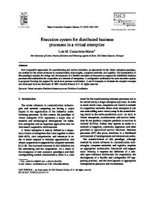
phases of the Requirements Engineering process. For example, in requirements elicitation scenarios are a behavioral specification, while in scenario analysis, scenarios are possible ways to use the system to accomplish some function the user desires. In validation, scenarios aim at demonstrating how the system will work once it is in operation. The results drawn from the Lubars study as well as the study of existing systems that use scenarios, were particularly promising. Recently, visualization techniques, which have been successfully used in programming and data visualization [7] [8] [9], have been also employed in various phases of the RE process [5] [10]. For example, Task/Actor simulation has been combined with animation for the dynamic modeling of organizations in [11]. This paper advocates that many benefits can be accrued by the application of animation techniques in the validation process; thus integrating the formality of conceptual models and scenarios with the interactive and user-friendly technology of animation. In addition, changes in the Specifications can be easily validated and their impact on the overall Business System could be evaluated by automatically generate and re-execute the same scenario, after the changes have been made on the Business System Schemata. A diagrammatic overview of the approach is given in figure 1. The conceptual models and metamodels are stored in a common Repository. Three models, developed as part of the ORES1 ESPRIT project [12], are used to capture the static and dynamic aspects of the Business System. The Scenarios Engine is the basis of the approach and is responsible for gathering and structuring information from the Repository in order to form the Validation Scenarios. The Scenarios Engine is also responsible for executing the scenarios and reporting all the interesting events and information to the Animation Engine to be visualized. The Animation Engine is the component responsible for animating the execution of a scenario. 1
The ORES project is a collaborative project between: 01 Pliroforiki, Greece; Clinica Puerta de Hierro, Spain; Information Dynamics, Greece; Royal Institute of Technology, Sweden; UMIST, U.K. The project is partly funded by the CEC under the ESPRIT III programme.
It is also responsible for transferring any user requests to the Scenarios Engine. The Animation Engine generates and updates simultaneously the Visual Views according to the events reported by the Scenarios Engine. A Visual View consists of a physical window and a set of graphical objects which are displayed within the window. Each View is sensitive to a set of graphical events, such as resizing and redrawing parts of the View’s window whenever this is necessary. Three Visual Views are generated by the Animation Engine, one for each conceptual model.
be validated by selecting a particular scenario to execute. Furthermore, if a change in the Business requires changes in the system, then only the Business System Schema has to be changed. Then by observing the execution of the same scenario, an indication of the impact of the change to other parts of the Business System can be evaluated and validated.
Visual Views
user requests
graphical events and information control and mode information
Animation Engine
Fisheye View
control & mode information
Repository Business System Data Business System Schema
instance information conceptual information
conceptual events & information
Scenarios Engine
Metamodel
Figure 1.
An Architecture for Animation for Validation
The stakeholder assists the Business System engineer in choosing a particular scenario and finding errors and omissions by observing and controlling the execution of the selected scenario. However, the user directly interacting with the tool is expected to be the Business System engineer. In case the stakeholder wishes to interact with the system can be helped by the Business System engineer in doing so. Therefore, the term user is used in this paper to denote both of them. Business System specifications are likely to change a lot during the RE process. In our approach once a Business System Schema has been developed it can
3.
The Validation Scenarios
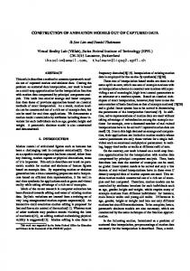
For the task of enterprise modeling it is important to capture both the structural as well as the behavioral aspects of the domain. Therefore, the conceptual modeling language which is used provides mechanisms for three conceptual views namely a structural view, a behavioral view and an active view, as shown in Figure 2. These three views are represented by the ERT, PID and CRL models respectively. Apart from these models, a query language which operates on ERT objects has been defined. The ERT-SQL
A AAAA AAAAAAAA AAAAAAAA AAAAAAAA AAAAAAAA AAAAAAAA AAAAAAAA AAAAAAAA AAAAAAAA AAAAAAAA AAAAAAAA AAAAAAAA AAAAAAAA AAAA AAAAAA AAAAAAAA AAAA AAAAAAAA AAAA AAAAAAAA AAAA AAAAAAAA AAAAAAAA AAAA AAAAAAAA AAAA AAAAAAAA AAAAAAAA AAAAAAAA AAAAAAAA AAAAA AAAAAAAA AAAAAAAA AAAAAAAA AAAAAAAA AAAAAAAA AAAAAAAA AAAAAAAA AAAAAAAA AAAAAAAA AAAAAAAA AAAAAAAA AAAAAAAA AAAAAAAA AAAAAAAA AAAAAAAA AAAAAAAA AAAAAAAA AAAAAAAA AAAAAAAA AAAAAAAA AAAAAAAA AAAAAAAA AAAAAAAA AAAAAAAAAAAA AAAAAAAA PID Schema A AAAA AAAA AAAA AAAA AAAA AAAA AAAA AAAA AAAA AAAA AAAA AAAA AAAA AAAA AAAA AAAA AAAA AAAA AAAA AAAA AAAAAAAA AAAAERT AAAAAAAA AAAA Schema AAAA AAAAAA AAAAAAAA AAAAAAAA AAAAAAAA AAAAAAAA AAAAAAAA AAAAAAAA AAAAAAAA AAAAAAAA AAAAAAAA AAAAAAAA AAAAAAAA AAAAAAAA AAAAAAAA AAAAAAAA AAAAAAAA AAAAAAAA AAAAAAAA AAAAAAAA AAAAAAAA AAAAAAAA AAAAAAAA AAAAAAAA AAAAAAAA AAAAAAAA AAAAAAAA A AAAA AAAA AAAA AAAA AAAAAAAA AAAAAAAA AAAA AAAAAAAA AAAA AAAAAAAA AAAA AAAAAAAA AAAAAAAA AAAA AAAAAAAA AAAA AAAAAAAA AAAA No AAAA viable AAAAAA AAAA AAAA AAAAAAAA AAAAAAAA AAAAAAAA AAAAAAAA AAAAAAAA AAAAAAAA AAAAAAAA AAAAAAAA AAAAAAAA AAAAAAAA P 4AAAA AAAA AAAA AAAA AAAA AAAA AAAA AAAA AAAA AAAA AAAA P 1AAAA recipient name A AAAA AAAA AAAA AAAA AAAA AAAA AAAAAAAA AAAAAAAA AAAA AAAAAAAA AAAAAAAA AAAAAAAA AAAAAAAA AAAAAAAA AAAAAAAA AAAA AAAAAAAA AAAAAAAA AAAAAAAA AAAAmedrec_no AAAAAAAA AAAAAAAA AAAATAAAA AAAAAAAA AAAA AAAAAAAA transplant Decide on AAAA AA AAAA AAAA AAAA AAAA AAAAAAAA AAAAAAAA AAAA AAAAAAAA AAAAAAAA AAAAAAAA AAAA AAAA AAAAAAAA AAAAAAAA AAAA AAAAAAAA AAAA Register Potential AAAA AAAA AAAA AAAA AAAA AAAA AAAA AAAA AAAA 0,n AAAA of AAAA 1,1 AAAA A AAAA AAAA AAAA AAAA AAAA AAAA AAAAAAAA AAAAAAAA AAAAAAAA AAAAAAAA AAAAAAAA AAAAAAAA AAAAAAAA AAAAAAAA AAAA AAAA AAAAAAAA AAAA AAAAof AAAAAAAA AAAAAAAA AAAAAAAA AAAAAAAA AAAA AAAA AAAAAAAA 1,1 has viable A AAAA AAAAAAAA AAAAAAAA AAAA AAAA AAAAAAAA AAAAAAAA AAAA AAAAAAAA AAAA AAAAAAAA AAAA AAAAAAAA AAAA AAAAAAAA AAAAAAAA AAAA Potential Recipient AA AAAAAAAA AAAA AAAAAAAA AAAA AAAAAAAA AAAAAAAA AAAA AAAAAAAA AAAA AAAAAAAA AAAA AAAAAAAA AAAA AAAAAAAA AAAAAAAA AAAAAAAA AAAA AAAA AAAA AAAA AAAA AAAA AAAA AAAA AAAA AAAA AAAA AAAA AAAA AAAA AAAA AAAA AAAA AAAA AAAA AAAA AAAA AAAA AAAA AAAA AAAA AAAA transplant T AAAAAAAAAA AAAAAAAAAAAA AAAAAAAAAAAAAAAA AAAAAAAAAAAAAAAA AAAAAAAAAAAA AAAAAAAAAAAA Recipient AAAAAAAAAAAAAAAA AAAAAAAAAAAA AAAAAAAA AAAA AAAAAAAA AAAAAAAA AAAA AAAAAAAA AAAA AAAAAAAA AAAA AAAAAAAA AAAA AAAAAAAA AAAAAAAA AAAAAAAA AAAA AAAAAAAA 1,n of AAAAAAAA AAAA AAAAAAAA AAAA AAAA AAAA AAAA AAAAAA AAAAAAAA AAAAAAAA AAAAAAAA AAAAAAAA AAAAAAAA AAAAAAAA AAAAAAAA AAAA AAAAAAAA AAAAAAAA AAAANew AAAA AAAAAAAA AAAAhas AAAA AAAA AAAAAAAA AAAAAAAA AAAAAAAA AAAAAAAA has 1,1 AAAAAAAA AAAAAAAA AAAAAAAA 1,1 AAAA P 1AAAA AAAAAA AAAAAAAA AAAAAAAA AAAAAAAA AAAAAAAA AAAA AAAAAAAA AAAAAAAA AAAA AAAAAAAA AAAA AAAA AAAAAAAA AAAA AAAAAAAA AAAAAAAA AAAAA AAAAAAAA AAAA AAAAAAAA AAAA AAAAAAAA AAAA AAAAAAAA AAAA AAAAAAAA AAAAAAAA AAAA AAAAAAAA AAAAAAAA AAAA AAAAAAAA AAAAsurgery T Doner Register AAAA AAAA T AAAA patient AAAAA AAAAAAAA AAAAAAAA AAAAAAAA AAAAAAAA AAAAAAAA AAAAAAAA AAAAAAAA AAAAAAAA AAAAAAAA AAAAAAAA AAAAAAAA AAAAAAAA AAAAAAAA AAAA AAAAAAAA AAAAAAAA AAAA AAAAAAAA AAAAAAAA AAAAAAAA AAAAAAAA AAAAAAAA AAAAAAAA AAAAAAAA AAAAAAAA AAAAAA AAAAAAAA AAAA AAAAAAAA AAAAAAAA AAAAAAAA AAAAAAAA AAAAAAAA AAAA AAAAAAAA AAAA AAAAAAAA AAAA AAAAAAAA AAAAof AAAA AAAA New 1,n AAAAAAAA AAAA AAAAAAAA AAAAAAAA AAAAAAAA AAAAAAAA AAAAAAAA AAAA AAAA AAAA AAAAAAAA AAAAAAAA AAAAAAAA AAAA AAAAAAAA 0,n AAAA A AAAAAAAA AAAAAAAA AAAAAAAA AAAAAAAA AAAAAAAA AAAAAAAA AAAAAAAA AAAAAAAA AAAAAAAA AAAAAAAA AAAAAAAA AAAAAAAA AAAAAAAA AAAAAAAA AAAAAAAA AAAAhas AAAAAAAA AAAAAAAA AAAAAAAA AAAAAAAA AAAAAAAA AAAAAAAA AAAAAAAA AAAAAAAA A AAAA AAAAAAAA AAAA PAAAA 6 AAAAAAAAAAAA P AAAA 7 AAAA Donor AAAAAA AAAAAAAA AAAAAAAA AAAA AAAAAAAA AAAAAAAA AAAAAAAA AAAAAAAA AAAAAAAA AAAA AAAAAAAA AAAAAAAA AAAA AAAA AAAA has T AAAA 0,n AAAA PlanAAAA forAAAA AAAAA AAAA AAAA AAAAAAAA AAAAAAAA AAAAAAAA AAAA AAAAAAAA AAAAAAAA AAAAAAAA AAAAAAAA AAAAAAAA AAAAAAAA AAAAAAAA AAAAAAAA AAAA AAAAAAAA AAAAAAAA AAAAAAAA AAAAAAAA AAAAAAAA AAAAAAAA AAAAAAAA AAAA AAAA AAAAAAAA Select AAAAAA AAAAAAAA AAAA AAAAAAAA AAAAAAAA AAAAAAAA AAAAAAAA AAAAAAAA AAAAAAAA AAAAAAAA AAAAAAAA AAAAAAAA AAAAAAAA 1,n AAAA of AAAA AAAAAAAA AAAAAAAA AAAAAAAA AAAA AAAAAAAA AAAAAAAA AAAAAAAA AAAAAAAA AAAA AAAA AAAAAAAA AAAAAAAA AAAA AAAA AAAAAAAA donor operation TAAAA optimal AAAAAA AAAA AAAA AAAAAAAA AAAA AAAAAAAA AAAAAAAA AAAAAAAA AAAAAAAA AAAAAAAA AAAA AAAAAAAA AAAA AAAAAAAA AAAAAAAA AAAAAAAA AAAAA AAAA AAAA AAAA AAAA AAAA AAAA AAAA AAAA AAAA AAAA AAAA AAAA AAAA AAAA AAAA AAAA AAAA AAAA AAAA AAAA AAAA AAAA AAAA AAAA AAAA AAAAAAAAAAAA AAAAAAAAAAAA AAAAAAAA AAAAAAAAAAAA AAAAAAAAAAAA AAAAAAAAAAAAAAAA AAAAAAAAAAAAAAAA AAAAAAAAAAAAAAAA donor AAAA AAAA AAAA AAAA AAAA AAAA AAAA AAAA AAAA AAAA AAAA AAAA AAAA AAAA AAAA AAAA AAAA AAAA AAAA AAAA AAAA AAAA AAAA AAAA AAAA AAAAAA AAAAAAAA AAAAAAAAAAAAAAAA AAAAAAAAAAAA AAAAAAAAAAAAAAAA AAAAAAAAAAAAAAAA AAAAAAAAAAAArejection AAAAAAAAAAAA AAAAAAAAAAAA AAAAAA AAAAAAAA AAAAAAAA AAAAAAAA AAAAAAAA AAAAAAAA AAAAAAAA AAAAAAAA AAAAAAAA AAAAAAAA AAAAAAAA AAAAAAAA AAAAAAAA AAAA AAAAAAAA AAAAAAAA AAAAAAAA AAAAAAAA AAAAAAAA AAAA AAAAAAAA AAAA AAAAAAAA AAAAAAAA AAAAAAAA AAAAAAAA AAAAAAAA AAAAAAAA AAAAAA AAAAAAAA AAAAAAAA AAAAAAAA AAAAAAAA AAAAAAAA AAAAAAAA AAAAAAAA AAAAAAAA AAAAAAAA AAAA AAAAAAAA AAAAAAAA AAAAAAAA AAAAAAAA AAAAAAAA AAAAAAAA AAAAAAAA AAAA AAAAAAAA AAAA AAAAAAAA AAAAAAAA AAAAAAAA AAAAAAAA AAAAAAAA AAAA AAAAAAAA AAAA AAAAAA AAAAAAAA AAAAAAAA AAAAAAAA AAAA AAAAAAAA AAAA AAAAAAAA AAAAAAAA AAAAAAAA AAAAAAAA AAAAAAAA AAAA AAAAAAAA AAAAAAAA AAAA AAAA AAAA AAAA AAAA AAAA AAAA AAAA AAAA AAAA AAAA AAAA AAAA AAAA AAAA AAAA AAAA AAAA AAAA AAAA AAAA AAAA AAAA AAAA AAAA AAAAA AAAAAAAA AAAAAAAAAAAA AAAAAAAAAAAA AAAAAAAAAAAA AAAAAAAAAAAA AAAAAAAACRL AAAAAAAAAAAAAAAA AAAAAAAAAAAA AAAAAAAAAAAA A AAAAAAAA AAAAAAAA AAAA AAAAAAAA AAAA AAAAAAAA AAAAAAAA AAAAAAAA AAAAAAAA AAAAAAAA AAAA AAAAAAAA AAAAAAAA AAAAAAAA AAAA AAAAAA AAAAAAAA AAAAAAAA AAAAAAAA AAAAAAAA AAAAAAAA AAAAAAAA AAAAAAAA AAAAAAAA AAAA AAAAAAAA AAAAAAAA AAAAAAAA AAAAAAAA AAAAAAAA AAAA AAAAAAAA AAAA AAAAAAAA AAAAAAAA AAAAAAAA AAAAAAAA AAAAAAAA AAAAAAAA AAAA AAAAAAAA AAAAAAAA AAAAAAAA ALL(Prothrombin_activity[>=0,