Aug 4, 2011 - ation of mobile terminal antennas at the 900 MHz frequency band is introduced. The proposed structure consists of two antenna elements.
Antenna shielding method reducing interaction between user and mobile terminal antenna J. Ilvonen, R. Valkonen, O. Kiveka¨s, P. Li and P. Vainikainen
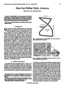
needed. The proposed antenna structure with a single-resonant matching circuit has an impedance bandwidth of 870 – 973 MHz (see Fig. 3). A corresponding reference structure is also investigated to obtain reliable evaluation of the proposed shielded antenna structure. In the reference structure the other element is excluded and the chassis is extended to be under the antenna element (see Fig. 1b).
A new method to decrease the effect of the hand and head on the operation of mobile terminal antennas at the 900 MHz frequency band is introduced. The proposed structure consists of two antenna elements. Depending on the use position, the better-performing antenna element is selected and the other is acting as a shield. It is shown by simulations that the proposed structure can improve the total efficiency with the hand by up to 4.8 dB and decrease the maximum specific absorption rate in the head by 30 –44% compared to the traditional single element structure.
100
CCE
chassis 50 z
y x
z
x y
a 2.5
10
CCE 1 chassis feed 1 feed 2 CCE 2
10
b 2.5
2
feed 1
CCE 1
y 10
feed 2
x z
CCE 2 50
c
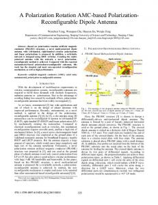
Fig. 2 Schematic view of proposed shielded antenna structure a Top view b Side view 1 c End view Dimensions in millimetres 0 reference shielding cases 1 and 2 shielding, passive floating
–2 S-parameters, dB
Introduction: The user of a mobile terminal affects the operation of the antennas within the terminal by absorbing a part of the radiated power into the body tissues and by causing a shift in the resonant frequency [1, 2]. This causes a decrease in efficiency, shortening the battery lifetime and deteriorating the reliable operation of the radio system. Typically, the closer the user is to the radiating antenna element, the more significant is its effect [3]. To fulfil the radiation exposure restrictions (specific absorption rate (SAR) limits), an antenna element is usually placed on the backside of the mobile handset, away from the head in the talk position. From the antenna operation point of view, this kind of antenna configuration is far from being optimal in many other use positions. For instance, when using the mobile terminal in a data mode (browsing position), the user’s fingers may cover the antenna element, reducing the radiation efficiency and causing frequency detuning [4]. The proposed shielded antenna structure consists of two non-self resonant capacitive coupling element (CCE) antennas [5]. The operation is demonstrated at the 900 MHz frequency band, although the same CCE could be used at practically any frequency band by tuning the operation frequency. In this Letter, an active antenna element refers to the case where the antenna element is switched on (feed connected) and a passive element refers to the case where the antenna element is switched off (floating or connected to the ground). The operational principle of the shielded structure is such that one antenna element is active at a time and the other is passive acting as a shield (see Figs. 1c and d). One of the elements can also be used as an extension of the ground plane to improve the shielding effect from electromagnetic exposure. The selection of the active antenna element is based on the use position. If the talking mode is used (terminal beside the head), the antenna element placed on the back side of the mobile terminal is selected (see Fig. 1d), and the passive antenna element is operating as a shield on the head’s side of the terminal. When the head is not beside the terminal, the antenna element placed on the front side of the terminal is active (see Fig. 1c).
–4 –6 –8
–10 –12 0.7
0.8
0.9
1.0
1.1
1.2
frequency, GHz
Fig. 3 Simulated S-parameters of reference and proposed shielding cases in free space
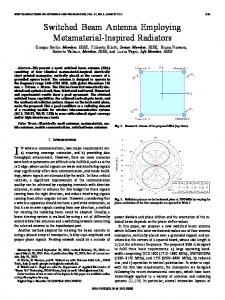
The simulations are made with homogeneous and anthropomorphic hand and head phantom models, SHO V2RB and SAM head, respectively, by SPEAG (see Fig. 1a). The phantom hand is based on the CTIA OTA test plan, revision 3.0 [6]. The minimum distance between the index finger and antenna element is 1 mm (see Fig. 1). The antenna structure is in the touch position on the right cheek of the SAM phantom (see Fig. 1) [7].
a reference
shielding case 1
shielding case 2
index finger 1
1
1 active
5 chassis
6 ear
cheek
b
1
passive
5
active
5 chassis
ear
cheek
c
1
active
5
passive
5 chassis
ear
cheek
d
Fig. 1 Antenna structure having active and passive antenna elements a SPEAG SHO V2RB phantom CAD model b Reference structure c Shielding case 1 d Shielding case 2 Dimensions in millimetres
Simulation results and discussion: The performance of the antenna structures is simulated using an FDTD-based commercial electromagnetic simulator SEMCAD X by SPEAG. The simulations are performed with a lossless matching circuitry and all dissipative losses of the antenna structure are neglected. The characteristics that have been studied are radiation efficiency (hrad), total efficiency (htot) and SAR (see Table 1). The mismatch efficiency (hmis) has the relation hmis ¼ htot 2 hrad.
Table 1: Radiation and total efficiencies and SAR values in head. Bold values refer to cases with best performances. SAR values are averaged to 10 g mass of tissue and normalised to 0.25 W average input power hrad (dB)
Antenna structure and user phantoms: The geometry and dimensions of the proposed structure can be seen in Fig. 2. The CCE antennas are nonself-resonant structures and thus an additional matching circuit is
htot (dB)
SAR (W/kg)
Case
Only hand
Only head
Hand + head
Only hand
Only head
Hand + head
With head
Ref.
24.7
26.8
211
26.5
27.5
213.1
1.7
0.9
1
21.1
28.9
29.7
21.7
213.2
213.9
2.2
2.1
2
24.8
24
29.1
26.5
25.9
210.9
1.2
0.5
ELECTRONICS LETTERS 4th August 2011 Vol. 47 No. 16
With head + hand
When the antenna structure is held in the hand (browsing position, no head), the optimal situation is to have the active element on the head’s side of the terminal (see case 1 in Fig. 1). In that case, the improvements in hrad and htot compared to the reference are 3.6 and 4.8 dB, respectively. In the talking position the optimal situation is to have the active element on the hand’s side of the terminal (case 2). The corresponding improvements in hrad and htot are 1.3 and 2.2 dB, respectively. The improvement in head SAR (max. 10 g avg) compared to the reference is 30% when only the head is present and 44% when both the head and the hand are present. With the hand, the main part of the improved htot and hmis results from the enlarged distance between the index and the active antenna element. The passive element as a shield helps to decrease the hand absorption by only 0.2 dB. On the other hand, the improvement in SAR values is mainly due to the shielding effect of the passive antenna element. In the hand-only case it could be useful to have the passive element floating (no ground connection), providing better bandwidth (Fig. 3). However, it is not beneficial to use the floating element with the head since the shielding effect is lost and SAR values are increased. Conclusions: A novel concept having a reduced user absorption and an improved SAR performance has been proposed and verified by simulations. The obtained results show that the proposed structure can increase the total efficiency with the hand by up to 4.8 dB and decrease the head SAR values by 30 – 44% compared to the traditional single element structure. However, the proposed structure requires a switching system, which was not implemented in this study. If the implementation losses, approximately 1 dB with current technology, were added to the results, the proposed structure would still perform much better compared to the reference. Future and ongoing work includes the development of the concept to be more suitable in real mobile terminals and measurements with a real prototype.
# The Institution of Engineering and Technology 2011 4 May 2011 doi: 10.1049/el.2011.1320 One or more of the Figures in this Letter are available in colour online. J. Ilvonen, R. Valkonen, O. Kiveka¨s and P. Vainikainen (Department of Radio Science and Engineering, Aalto University School of Electrical Engineering, SMARAD, PO Box 13000, Aalto FI-00076, Finland) E-mail: janne.ilvonen@aalto.fi P. Li (Nokia Corporation, Helsinki, Finland) References 1 Pelosi, M., Franek, O., Knudsen, M.B., and Pedersen, G.F.: ‘Influence of dielectric loading on PIFA antennas in close proximity to user’s body’, Electron. Lett., 2009, 45, (5), pp. 246–247 2 Valkonen, R., Ilvonen, J., Rasilainen, K., Holopainen, J., Icheln, C., and Vainikainen, P.: ‘Avoiding the interaction between hand and capacitive coupling element based mobile terminal antenna’. Proc. 4th EuCAP, Rome, Italy, April 2011, pp. 2934– 2938 3 Pelosi, M., Franek, O., Knudsen, M.B., and Pedersen, G.F.: ‘User’s proximity effects in mobile phones’. Proc. 3rd EuCAP, Berlin, Germany, March 2009, pp. 1022–1024 4 Li, C.-H., Ofli, E., Chavannes, N., and Kuster, N.: ‘Effects of hand phantom on mobile phone antenna performance’, IEEE Trans. Antennas Propag., 2009, 57, (9), pp. 2763– 2770 5 Villanen, J., Ollikainen, J., Kiveka¨s, O., and Vainikainen, P.: ‘Coupling element based mobile terminal antenna structures’, IEEE Trans. Antennas Propag., 2006, 54, (7), pp. 2142– 2153 6 Test Plan for Mobile Station Over the Air Performance, CTIA, Tech. Rep., Revision 3.0 Std, April 2009 7 IEEE Recommended Practice for Determining the Peak Spatial-Average Specific Absorption Rate (SAR) in the Human Head from Wireless Communications Devices: Measurement Techniques (IEEE Std 15282003), IEEE Standards Coordinating Committee Std, 2003
ELECTRONICS LETTERS 4th August 2011 Vol. 47 No. 16