0.0. Xcomp Compounding reactance for voltage control, pu. 0.0. Interconnection Customer provided data in bold, all other data is default/typical data. H-2 ...
Appendix H Transient Stability Modeling
Generator Model Model Name:
genrou
Description
Solid rotor generator represented by equal mutual inductance rotor modeling
Prerequisites:
Generator present in load flow working case
Inputs:
Network boundary variables, Field Voltage, Turbine Power
Invocation:
genrou [] { } :
Parameters: EPCL Variable MVA Tpdo Tppdo Tpqo Tppqo H D Ld Lq Lpd Lpq Lppd Ll S1 S12 Ra Rcomp Xcomp
Description MVA rating D-axis transient rotor time constant D-axis sub-transient rotor time constant Q-axis transient rotor time constant Q-axis sub-transient rotor time constant Inertia constant, sec Damping factor, pu D-axis synchronous reactance Q-axis synchronous reactance D-axis transient reactance Q-axis transient reactance D-axis subtransient reactance Stator leakage reactance, pu Saturation factor at 1 pu flux Saturation factor at 1.2 pu flux Stator resistance, pu Compounding resistance for voltage control, pu Compounding reactance for voltage control, pu
Data 72.0 7.0 0.039 2.4 0.22 1.15 0.81 2.74 2.58 0.26 0.24 0.16 0.16 0.104 0.574 0.005 0.0 0.0
Interconnection Customer provided data in bold, all other data is default/typical data.
H-2
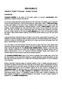
GENROU Block Diagram
H-3
Exciter Model Model Name:
esac7b
Description
IEEE (2005) type AC7B excitation system
Prerequisites:
Generator model ahead of this model in dynamic models table
Inputs:
Compounded generator terminal voltage, generator field current, generator speed
Invocation:
esac7b [] { } :
Parameters: EPCL Variable Tr Kpr Kir Kdr Tdr Vrmax Vrmin Kpa Kia Vamax Vamin Kp Kl Te Vfemax Vemin Ke Kc Kd Kf1 Kf2 Kf3 Tf E1 S(E1) E2 S(E2) spdmlt
Description Filter time constant, sec. Regulator proportional gain, p.u. (> 0. if Kir = 0.) Regulator integral gain, p.u. Regulator derivative gain, p.u. Derivative gain washout time constant, sec. Maximum regulator output, p.u. Minimum regulator output, p.u. Amplifier proportional gain. (> 0. if Kia = 0.) Amplifier integral gain, p.u. Maximum amplifier output, p.u. Minimum amplifier output, p.u. Exciter field voltage source gain, p.u. Exciter field voltage lower limit parameter, p.u. Exciter time constant, sec. (> 0.) Exciter field current limit parameter, p.u. Efd Minimum exciter ouput voltage, p.u. Efd Exciter field resistance constant, p.u. Rectifier regulation factor, p.u. Exciter internal reactance, p.u. Field voltage feedback gain, p.u. Exciter field current feedback gain, p.u. Rate feedback gain, p.u. Rate feedback time constant, sec. (> 0.) Field voltage value 1, p.u. Saturation factor at E1 Field voltage value 2, p.u. Saturation factor at E2 If = 1, multiply output (Efd) by generator speed
Data 0.0 25.85 25.85 0.0 0.0 9.44 0.0 15.2 2.17 1.0 -1.0 306.321 1.0 1.2 20.0 0.0 1.0 0.382 0.0 0.0 0.4664 0.0 1.0 8.13 0.228 10.84 1.56 0.0
Interconnection Customer provided data in bold, all other data is default/typical data.
H-4
Model Name:
esac7b
Description
IEEE (2005) type AC7B excitation system
Prerequisites:
Generator model ahead of this model in dynamic models table
Inputs:
Compounded generator terminal voltage, generator field current, generator speed
Invocation:
esac7b [] { } :
Parameters: EPCL Variable Tr Kpr Kir Kdr Tdr Vrmax Vrmin Kpa Kia Vamax Vamin Kp Kl Te Vfemax Vemin Ke Kc Kd Kf1 Kf2 Kf3 Tf E1 S(E1) E2 S(E2) spdmlt
Description Filter time constant, sec. Regulator proportional gain, p.u. (> 0. if Kir = 0.) Regulator integral gain, p.u. Regulator derivative gain, p.u. Derivative gain washout time constant, sec. Maximum regulator output, p.u. Minimum regulator output, p.u. Amplifier proportional gain. (> 0. if Kia = 0.) Amplifier integral gain, p.u. Maximum amplifier output, p.u. Minimum amplifier output, p.u. Exciter field voltage source gain, p.u. Exciter field voltage lower limit parameter, p.u. Exciter time constant, sec. (> 0.) Exciter field current limit parameter, p.u. Efd Minimum exciter ouput voltage, p.u. Efd Exciter field resistance constant, p.u. Rectifier regulation factor, p.u. Exciter internal reactance, p.u. Field voltage feedback gain, p.u. Exciter field current feedback gain, p.u. Rate feedback gain, p.u. Rate feedback time constant, sec. (> 0.) Field voltage value 1, p.u. Saturation factor at E1 Field voltage value 2, p.u. Saturation factor at E2 If = 1, multiply output (Efd) by generator speed
Data 0.0 3.89 3.89 0.0 0.0 6.74 -6.74 117.7 26.87 1.0 -0.95 12.08 10.0 3.0 15.2 0.0 1.0 0.13 1.14 0.194 0.0 0.0 1.0 6.67 1.951 5.0 0.156 0.0
Interconnection Customer provided data in bold, all other data is default/typical data.
H-5
ESAC7B Block Diagram Kp Vt Vs Vref [vsig [vref] ]
Vuel [vuel ]
+
1 [ v c o m p ] 1 + sTr
Vc
-
Vrmax
Σ
Kpr +
s Kdr Kir + s 1+ sTdr S1
S0
1
1
+ +
-
[speed ]
Vfemax - Kd Ifd Ke + Se(Ve)
Vamax
S5
+
Σ
Kpa +
-
Kia s
Vr
X
Vamin
Ve
1
Σ
+
S3
-Kl Vfe
Efd [efd]
X Fex
Vemin F(In)
+
Σ
spdmlt
sTe
-
S2
Vrmin Vf
Va
0
Kf 2 In
+
K e+ S e ( V e ) Vfe
s Kf 3 1+ sTf
Kc Ifd / Ve
+
Σ +
S4
Kd
Kf 1
H-6
Ifd [ladIfd]
Governor/Turbine Model Model Name:
ieeeg1
Description
IEEE steam turbine/governor model (with deadband and nonlinear valve gain added)
Prerequisites:
One or two generator models ahead of this model in the dynamic models table
Inputs:
Shaft speed
Invocation: Parameters: EPCL Variable MWCap K T1 T2 T3 Uo Uc Pmax Pmin T4 K1 K2 T5 K3 K4 T6 K5 K6 T7 K7 K8 db1 eps db2 GV1 Pgv1 GV2 Pgv2 GV3 Pgv3 GV4 Pgv4 GV5 Pgv5 GV6 Pgv6
ieeeg1 [] { } [] { } : [mwcap=]
Description Maximum turbine output (MW) Governor gain (reciprocal of droop), p.u. Governor lag time constant, sec. Governor lead time constant, sec. Valve positioner time constant, sec. Maximum valve opening velocity, p.u./sec. Maximum valve closing velocity, p.u./sec (< 0.) Maximum valve opening, p.u. of mwcap. Minimum valve opening, p.u. of mwcap Inlet piping/steam bowl time constant, sec. Fraction of hp shaft power after first boiler pass Fraction of lp shaft power after first boiler pass Time constant of second boiler pass, sec Fraction of hp shaft power after second boiler pass Fraction of lp shaft power after second boiler pass Time constant of third boiler pass, sec. Fraction of hp shaft power after third boiler pass Fraction of lp shaft power after third boiler pass Time constant of fourth boiler pass, sec Fraction of hp shaft power after fourth boiler pass Fraction of lp shaft power after fourth boiler pass Intentional deadband width, Hz. Intentional db hysteresis, Hz. Unintentional deadband, MW Nonlinear gain point 1, p.u. gv Nonlinear gain point 1, p.u. power Nonlinear gain point 2, p.u. gv Nonlinear gain point 2, p.u. power Nonlinear gain point 3, p.u. gv Nonlinear gain point 3, p.u. power Nonlinear gain point 4, p.u. gv Nonlinear gain point 4, p.u. power Nonlinear gain point 5, p.u. gv Nonlinear gain point 5, p.u. power Nonlinear gain point 6, p.u. gv Nonlinear gain point 6, p.u. power
Data 48.5 20.216 7.89 0.01 0.01 99.0 -99.0 1.2 0.8 0.01 1.0 0.0 0.01 0.0 0.0 0.01 0.0 0.0 0.0 0.0 0.0 0.0 0.0 0.0 0.0 0.0 0.0 0.0 0.0 0.0 0.0 0.0 0.0 0.0 0.0 0.0
Interconnection Customer provided data in bold, all other data is default/typical data.
H-7
IEEEG1 Block Diagram
H-8
Power System Stabilizer Model Name:
pss2a
Description
Dual input Power system stabilizer (IEEE type PSS2A)
Prerequisites:
Generator model ahead of this model in dynamic models table
Inputs:
Generator shaft speed, frequency of generator terminal, system bus voltage, generator electric power or accelerating power, voltage amplitude of generator terminal bus or system bus, current amplitude specified branch
Invocation:
psssa [] { } :
Parameters: EPCL Variable J1 K1 J2 K2 Tw1 Tw2 Tw3 Tw4 T6 T7 Ks2 Ks3 Ks4 T8 T9 n m Ks1 T1 T2 T3 T4 Vstmax Vstmin a Ta Tb
Description Input signal #1 code (shaft speed) Input signal #1 remote bus number Input signal #2 code (generator electrical power) Input signal #2 remote bus number First washout on signal #1, sec. Second washout on signal #1, sec. First washout on signal #2, sec. Second washout on signal #2, sec. Time constant on signal #1, sec. Time constant on signal #2, sec. Gain on signal #2 Gain on signal #2 Gain on signal #2 Lead of ramp tracking filter Lag of ramp tracking filter Order of ramp tracking filter Order of ramp tracking filter Stabilizer gain Lead/lag time constant, sec. Lead/lag time constant, sec. Lead/lag time constant, sec. Lead/lag time constant, sec. Stabilizer output max limit, p.u. Stabilizer output min limit, p.u. Lead/lag num. Gain. (not in IEEE model) Lead/lag time constant, sec. (not in IEEE model) Lead/lag time constant, sec. (not in IEEE model)
Data 1.0 0.0 3.0 0.0 2.0 2.0 2.0 0.0 0.0 2.0 0.237 1.0 1.0 0.5 0.1 1.0 5.0 15.0 0.15 0.03 0.15 0.03 0.1 -0.1 1.0 0.0 0
Interconnection Customer provided data in bold, all other data is default/typical data.
H-9
PSS2A Block Diagram
H-10