The task of the main functions are as follows: Fun. .... In every couple the first value is the number of the level, the second is the height of the ... number (eg. L01).
APPENDIX: Using "3dbuildingtranslator.py" Module Originally, Abaqus was designed to run "Input files" that contains the full description of the model and analysis type. Then ABAQUS introduced ABAQUS/CAE along with ABAQUS Scripting interface to simplify modeling process and increase the productivity interactively. ABAQUS Scripting interface is an application programming interface to the models and data used by Abaqus[Part I: An introduction to the Abaqus Scripting Interface]. This interface is an extension of the Python object-oriented programming language and serves on transforming the graphical shapes and properties of the model entered interactively into "Input file" that runs abaqus. Nevertheless, not all the modeling techniques used by input file formats were incorporated into ABAQUS/CAE. One of them is the rebar property for beam elements; the other is semi-infinite elements introduced to simulate the soil boundaries in soil-structure interaction analysis. In this module (3dbuildingtranslator.py), we introduce the Python script capabilities that take full advantage of ABAQUS/CAE productivity and simplicity, in addition to incorporating the unsupported properties of ABAQUS/CAE. 3dbuildingtranslator.py consists of 9 main functions and 14 sub-functions (called by main functions or sub-functions). The task of the main functions are as follows: Fun. GetAmplitude(): Reads earthquake accelerations time-history file and prepare the amplitude of it to be used by ABAQUS. Fun. GetSection(): After reading script of building model, creates the building's library of all sections (beams, columns, walls, and slabs). Fun. CoordsNet(): Spatially creates the building's all vertices points (vertices of beams, columns, walls, and slabs). Fun. FramePartCreat(): Depending on points created previously this function creates all frame members (columns and beams) of the model in what is called Frame Part. Fun. ShellPartCreat(): Depending on points created previously this function creates all flat members of the model (walls and slabs) of the model in what is called Shell Part. Fun. TieMembers(): To join the frame part members intersecting/running along with shell part members as they are in the actual building. Fun. SubStructure(): Either fix the columns and walls to the ground at foundation level if no soil structure interaction is considered, or creates foundations, soil, and interface between them with quiet soil boundaries to simulate soil-structure interaction behavior if required. Fun. Analize(): According to type of analysis (natural frequency, nonlinear dynamic time history) this function creates steps of analysis with suitable loadings and job of analysis. Fun. InputModification(): Creates input file of the job, Inserts rebar data in the input file, and infinite elements for quiet soil boundaries if soil structure interaction is activated.
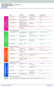
A.1 Flowchart of modeling by "3dbuildingtranslator.py":
Start ABAQUS > Run Script ‘3DBuildingTranslator.py’ Error message
Read Building model script file. ‘*.sinp’
N Create Amplitude
Y
Amplitude file found?
Fun. GetAmplitude()
Create Section Library
Fun. GetSection()
Create array of vertices
Fun. CoordsNet()
Create Frame Part Create Shell Part
Create Model of Building
Add BCs to Model
Add Analysis Data to Model
Write and Modify Input File
Fun. FramePartCreat()
Fun. ShellPartCreat()
Fun. TieMembers()
Fun. SubStructure()
Fun. Analize()
Fun. InputModification()
End
A.1 Script file (*.sinp file) format: Using text editor (Preferably notpad++) prepare text file script that describes the building you want to model to resemble the next excerpt noting that the first portion of the text contains individual parameters explained accordingly at the respective line. The second portion (after ### line) contains six arrays best to be explained by an example: #Start copy here AmpDirc = "Y" # Direction of Earthquake "X" or "Y" or "Z" Analysis = "Quak" # Type of Analysis "Freq"=frequency or "Quak"=NRHA Interaction = "Yes" # Soil Struction Interaction "Yes" or "No" Interface = "Rigid" # Interface of footings with soil "Rigid" or stiff SeedSizeF = 1000 # Max size of Beam Finite element mm SeedSizeS = 1000 # Max size of Shell Finite element mm SoilSedMin = 1000 # Max size of soil F.elements near building mm SoilSedMax = 3000 # Max size of soil F.elements far from building mm Gravity = 9810. # Gravetational Acceleration of Earth mm / Sec2 SlabMass = 8.155E-07 # Mass of Slab loads Per Area Ton / mm2 WallMass = 2.039E-09 # Mass of Wall loads Per Area Ton / mm2 Wn = 16.943 # Frequency of mode of vibration rad / Sec Zeta = 0.05 # Assumed ratio of damping in the model GamSoil = 1.8e-9 # Mass Density of soil ton / mm3 ESoil = 1.e2 # Elastic modulus of soil MPa MuSoil = 0.4 # Poisson ratio of soil FootingsD = 1500 # Depth of Footings mm ExtendSX = 20000. # Extending soil in X direction mm ExtendSY = 20000. # Extending soil in Y direction mm ExtendSZ = 20000. # Extending soil in Z direction mm ########################################################################################## Levels =[[-1, -3500.],[ 0, 0.],[ 1, 3500.],[ 2, 7000.]] Axis ={'Xaxis':{'A':0.0,'B':3000.0,'C':7000.0,'D':10000.0},'Yaxis':{'01':0.0,'02': 4000.0,'03': 9000.0,'04': 13000.0}} Sections = {'Sec1' : 'MatC24S420DiRec250x400RC8x20x30x1I5x20x30x1I8x20x30x1I5x20x30x1',…….} FrameParts = {'Columns':{ 'A01L00':('Sec1',0.0),'A02L00':('Sec1' ,0.0), …},'Beams':{'B0020L02':['A02','Sec3','B02','Sec3','C02','Sec3','D02'],…}} ShellParts = {'Slabs':{ 'S0001L00':(['A01','A02','B02','B01','A01'],'Sec10',SlabMass),...},'Walls':{ 'W0001L00':(['A01','B01'],'Sec11',WallMass),...,'WP001L01':(['D02','D03'],'Sec11',WallMass),…}} Footings = {'A01L00':(1000,),…} #End copy here
A.2 Creating the arrays of the model. Example: A building has the plan view and elevation shown.
Figure A.1 Right: Plan view of building. Left: Elevation of building.
Wall 'W0001L02' Wall 'WP001L02'
Column 'A01L00' Slab 'S0002L00'
Figure A.2 Member’s code method in modeling text 1-
2-
3-
Levels =[…] Is a list of couples. In every couple the first value is the number of the level, the second is the height of the level with respect to origin considered in the building drawings. Here the key (name) of any member (column, beam, slab, wall,…) ends with the level they belong to (e.g. column 'A01L00' belongs to Level00, and Beam 'B0003L01' belongs to Level01 and likewise.) Axis ={‘Xaxis’:{‘A’:0.0,…….},’Yaxis’:{‘01’:0.0,……}} Is a dictionary that contain two dictionaries the first is ‘Xaxis’ which refers to all axis that are parallel to global X axis, every axis has a key (alphabets for X axis) the value corresponds to the key is the distance from X axis. The second dictionary is ‘Yaxis’. It is the same as ‘Xaxis’ dictionary but with respect to global Y axis. Keys of ‘Yaxis’ are integers (See figureA.1 right). Sections ={'Sec1':'MatC24S420DiRec250x400RC8x20x30x1I5x20x30x1I8x20x30x1I5x20x30x1' , ……} Is a dictionary of all sections in the model (sections of columns, beam, walls, and slabs) the key refers to the section name that might be used by several members, the corresponding value is the parameters of the section explained as follows: Side2 a) Section Parameters Layer4
Side3
Side1
Layer3 Layer2 Layer1 b) 1m width shell section
Side4 c) Beam Cross section
Figure A.3 Explanation of section parameters Parameters of the section: A is a Concrete material. Number preceded by C is the value of concrete’s f’c. B is for Reinforcement in the section. Number preceded by S is the value of fy of steel.
4-
C is the shape of the cross section. If “Rec”, “Tee”, or “Eye” the section profile is a beam’s rectangular, tee, or I shape respectively. If C is “Thi” then the section is for 1 m slice width of shell section (for slab or wall members). D is the dimensions of the section when C refers to a beam section (“Rec”, “Tee”, or “Eye”), or thickness of shell thickness if value of C is a shell section (“Thi”). E, F, G, and H are the reinforcement of the section and they refer either to side1, side2, side3, and side4 respectively if it is a beam’s section, or layer1, layer2, layer3, and layer4 respectively if it is a shell section (figure A.3). In each one there are four values separated by three ‘x’s, if the section is a beam’s then the 1st value is number of bars, the 2nd is diameter of the bars, the 3rd is thickness of concrete cover, and the 4th is the number of bar rows. If the section is for shell then the 1st value is number of bars@1m, the 2nd is the diameter of the bars, the 3rd is thickness of concrete cover and the 4th is for orientation angle of the bars with respect to shell orientation.
FrameParts = {‘Columns’:{'A01L00':('Sec1',0.0),….} , ‘Beams’:{ 'B0020L02': ['A02','Sec3','B02','Sec3','C02','Sec3','D02'] }} Is a dictionary that contains two dictionaries the first is ‘Columns’ and every member in this dictionary has a key that refers to a column in some level, therefore the key represents the axis intersecting points of plan view of the building (see figure A.1 right) followed by level number (see figure A.1 left). The values correspond to this key are the section key used in this column and a lumped mass value at its top if any exists (unit is ton). The second dictionary contained in this dictionary is the ‘Beams’ dictionary. The key of the beam represents an arbitrary number of four figures preceded by ‘B’ letter and followed by level number (eg. L01). Values corresponding to the beam key are the axis intersecting points of the plan view along which the beam runs, separated by the section key of every span between any two sequential points. 5-
ShellParts = {'Slabs':{ 'S0001L00':(['A01','A02','B02','B01','A01'],'Sec10',SlabMass),...} ,'Walls':{ 'W0001L00':(['A01','B01'],'Sec11',WallMass),..., 'WP001L01':(['D02','D03'],'Sec11',WallMass),…}}
Is a dictionary that contains two dictionaries the first is ‘Slabs’ and every member in this dictionary has a key that refers to a slab in its smallest configuration (the key must begin with an ‘S’). The values correspond to this key are the axis intersecting points at the vertices of the slab ordered counterclockwise along the vertices with the last point is the first one in this order. Then the section used in the slab is referred to by a section key, and followed by the value of mass distributed on this slab (with ton/mm2 units). The second dictionary is ‘Walls’ with key as explained before and values corresponding are points of begging and end of the wall, section used in the wall, and mass distributed on the wall if other than sefweight of the wall is to be considered. 6-
Footings = {'A01L00':(1000,),…}
Is a dictionary that represents the footings of the building under columns (individual footings) and under the walls (continuous footings). The key is the same as the key of the column or the wall under which the footing is created and the value corresponds is the half width of the footing at all sides.