Application Centric Cloud Management Sunirmal Khatua
Anirban Ghosh
Nandini Mukherjee
Department of Computer Science and Engineering University of Calcutta, India Email:
[email protected]
School of Mobile Computing and Communication Jadavpur University, India Email:
[email protected]
Department of Computer Science and Engineering Jadavpur University, India Email:
[email protected]
Abstract—In recent years most of the cloud computing community adopt an infrastructure centric approach to optimize the cost of cloud resources considering both Cloud Computing Service Users(CCSU) and Cloud Computing Service Providers(CCSP). In this paper we have brought up the concept of Application Centric Cloud. With Application Centric Cloud we propose an architecture to provide a generalized framework for auto deploying, sharing, providing scalability, robustness and availability of any cloud based application. Along with application independence, the framework also considers CCSP independence so that an application can use resources across providers.
I. I NTRODUCTION Virtualization [1] [2] is one of the key technologies that makes modern computers powerful and versatile. In the past enterprises used to deploy their applications within their own dedicated physical servers or data centers that helped them to gain high flexibility of managing the infrastructure at the cost of lower resource utilization. Then they tried to consolidate their applications within a shared infrastructure for gaining better resource utilization at the cost of lower flexibility since changing any one’s application may affect others. Finally they used virtualization and cloud computing technologies to provide both flexibility and better resource utilization at the cost of high complexity of managing and optimizing the resource utilization of an application. Buyya et al in their paper [3] defines cloud computing as: “A Cloud is a type of parallel and distributed system consisting of a collection of interconnected and virtualized computers that are dynamically provisioned and presented as one or more unified computing resources based on service-level agreements established through negotiation between the service provider and consumers”. Cloud computing incorporates Infrastructure-as-a-Service (IaaS), Platform-as-a-Service (PaaS) and Software-as-aService (SaaS) and includes many other technology trends related to cluster computing, grid computing and utility computing [4]. The above mentioned services are generally delivered through data centers with different levels of virtualization technologies. There are basically two broad categories of clouds. In the first category, computing instances are created and provided on demand. Amazon’s EC2 Services [5] is an example of this category. The second category provides computing capacity on demand. One example of this category is Google’s MapReduce Application [6]. In the first case, scalability is achieved by scaling the computing instances,
whereas in the second case, scalability is achieved by scaling the computing capacity through aggregating the provisioned computing instances. Cloud computing is often used with utility computing pay-per-use model [7]. In such cases it offers reduced capital expenditure, low entry barrier and scaling up on demand. Thus, the key issues of a standard cloud based application are managing and providing virtualized resources, dynamic scalability of the virtualized resources and incorporating pay-per-use (utility) services. In this paper we focus on the issues of dynamic provisioning and dynamic scaling of virtualized resources. The other issues are assumed to be taken care of by the cloud provider such as Amazon EC2 or any private cloud built with tools like Eucalyptus [8] and Open Nebula [9]. One major requirement for a solution to optimal resource utilization is monitoring the resource health. On the basis of the resource health information and application context, virtual resources for an application can be increased or decreased. In this paper we propose Application Centric Cloud architecture for deploying, monitoring and optimizing the virtual resources deployed for a cloud application. A brief discussion of related work is presented in Section II and the proposed Application Centric Cloud architecture is discussed in Section III. Section IV summarizes the preliminary implementation of the proposed architecture and Section VI concludes with a direction of future work. II. P RIOR W ORK In high performance computing research, optimal resource utilization has always been considered as one of the major challenges. Certain resource utilization problems arise even in simple environments, like individual workstations. They are further aggravated in complex environments, particularly in those which are dynamic and heterogeneous. Some solutions have been proposed in the literature for traditional environments like clusters. These solutions are mainly based on techniques for dynamic load balancing. However, not much work have been carried out for virtual environments in this regard. Amazon has released a mechanism called Auto Scaling [10] that automatically scales the client’s EC2 capacity up or down according to the conditions defined by the client with the help of Amazon Cloud Watch [10]. However it fails to provide a generalized framework for optimal use of resources deployed for a cloud based application since an
infrastructure centric optimization was adopted. Therefore, the owner of a cloud application fails to integrate their own optimization rules specific for that application. Moreover, an application is not allowed to use resources from different CCSP. On the contrary, our proposed architecture adopts an application centric optimization mechanism. The Application Centric Cloud architecture focuses on establishing a generalized framework which is independent of the cloud providers and cloud applications. The major goal of this architecture is achieving a cost effective, fault tolerant and auto scalable web application deployment across cloud providers. III. A PPLICATION C ENTRIC C LOUD A RCHITECTURE The on-demand availability of resources and the pay-per-use model of cloud computing paradigm adds a new dimension in the possibility of optimizing virtual resources. Application Centric Cloud focuses on the optimization of such resources used for a web application deployed over the Cloud. It follows a top down approach to define the cloud as opposed to the bottom up approach used with infrastructure centric cloud. With bottom up approach we first define the infrastructure, then define the platform and finally deploy the application within the defined platform. With top down approach we first define the application, then define the platform needed by the application and finally find out the infrastructure providing the platform. Accordingly, we propose to define an application in the Application Centric Cloud formally with the following tuples: A = (T, R, Rm , P, U, M ) (1) where T is the set of tiers, ({t}) R is the set of resources, ({r}) Rm : R → T P is the set of policies, ({p}) U is the set of users ({u}) M is the monitoring subsystem and M = (E, W, Em , Wm )
A. Layers of Application Centric Cloud Architecture
(2)
where E is the set of events, ({e}) W is the set of workflows ({w}) Em : E → T | E → R Wm : W → E Every web application consists of a number of tiers (T) (even a standalone server can also be considered to be based on a single tier). Every tier uses specific resources (R) in order to implement the functionality of that tier (e.g. a database tier may use MySQL nodes as its resources). Application Centric Cloud uses a service stack (refer to Fig.1) maintained by each provider and provides a uniform interface to the user while provisioning the resources (R) for a particular tier(T). There are different types of resources like virtual machine, virtual storage, virtual network etc which may be provided by different providers. For example Elastic Block Storage(EBS) is a virtual storage provided by Amazon AWS. So R can be represented as R = ((α1 , β1 ), (α2 , β2 ), (α3 , β3 ), ......, (αn , βn ))
where , α is the type of the resources (EBS, Instance etc) and β is the resource provider details. P is the policy defined by the resource provider. Policy may vary from provider to provider. As for example security policy for Amazon EC2 supports X.509 key based authentication whereas Rackspace uses password based authentication. The key component of a cloud application in the Application Centric Cloud is the monitoring subsystem, M . It defines two entities namely events(E) and workflows(W). Events are defined as changes in states of a resource or a tier. Examples of events can be cited with server died, service died, a tier overloaded or under loaded etc. A workflow is a sequence of actions performed by the monitoring subsystem to fine tune the resources for an application at the occurrence of a specific event. Workflow may also be complex where one workflow kicks off (initiates) other workflows, either synchronously or asynchronously, for achieving the final goal. It also defines two mappings: Event Mapping - Em and Workflow Mapping - Wm . Em defines relationships either among tiers and events or among resources and events. For example, tier overloaded or under loaded events can be defined at the tier level whereas server died or service died may be defined at the resource level. Wm defines the relationships among events and workflows that allow the monitoring subsystem to kick off specific workflows at a particular event. Based on the above definition of a cloud application, different layers of the architecture and its functioning are described in the next two subsections.
(3)
The Application Centric Cloud architecture consists of three layers, which are: Infrastructure layer, Optimization layer and Application layer. The components that span over the three layers include virtual resources, a Provisioner, a Deployer, a Controller, a Monitor, a Policy-Arbitration-QoS module, and an Application Repository. Infrastructure layer provides the resource pool for the deployed application. Resources can be provisioned from public providers like Amazon EC2, Flexiscale, GoGrid [11] [12] etc. or from the private providers that allow a deployer to use his own infrastructure. One can establish his own private cloud with tools like Eucalyptus or Onen Nebula. Since an application needs the resources on demand the resources must be provisioned through a virtualization technology. Again the Application Centric Cloud allows the use of third party resources. So the infrastructure layer can’t use virtualization technology directly. Instead it uses Cloud Computing technology and Unified Provider API (refer to Fig. 1) to provide virtualization transparency to upper layers. Optimization layer is responsible to optimize the resources during first time deployment as well as during the life time of the deployed application through a feedback system [13]. The Deployer module in this layer uses the Application Repository, Policy-Arbitration-QoS and Provisioner module to provision the resources in an optimal way as described in later sections.
Fig. 1.
The Application Centric Cloud Architecture
The application definition is stored in the application repository. The Policy module maintains various strategies and priorities for scheduling the resources. In the Arbitration module, some of the strategies are overruled by experts manually. Thus the strategies in the Policy module consider long term goals whereas the strategies in the Arbitration module consider only the local goals. QoS module defines the reliability, response time, security and integrity issues for the deployed application. For example, security strategies defined in the QoS determines which tier (database tier, application tier etc.) of the application should be deployed in the private infrastructure. Similarly reliability in QoS determines how many backup nodes need to be maintained for the application. The Provisioner module along with Unified Provider API provisions the resources across providers required by the application. It uses delegate design pattern to solve the issue of heterogeneous request and response formats for different providers. The Deployer module decides the resource requirements with the information from Policy-Arbitration-QoS module and uses the Application Repository and Provisioner module to deploy the application onto the scheduled resources. The Monitor and the Controller modules along with the Unified Event API implement the feedback control system to optimize the resources during the life time of a deployed application. The feedback control system relies on event generation mechanism and along with the event it provides necessary information required for optimization. Once an event is received the Controller module uses similar mechanism as used by the Deployer module to reprovision the resources. The Application layer allows an end user to deploy any web application within the Cloud without modifying its code. The Unified Client API is used to support heterogeneous application formats and the Application Repository module is used to store application data along with application metadata. The application data stores the application in the forms of scripts, ear file, war file etc. The application metadata stores information about the application in the format of an application definition (refer to the formal definition of a cloud application).
B. Functioning of Application Centric Cloud Architecture Application Centric Cloud works in two phases, namely Event Generation phase and Optimization phase. In the Event Generation phase, events are generated to identify any change in the state of the deployed application e.g. load to an application (such as number of requests) increases or decreases. Once such an event is received, in the Optimization phase resource requirements for the application is analyzed and resources are reprovioned according to the requirements. The two phases of the architecture are described in detail in the next two subsections. 1) Event Generation Phase: An application in Application Centric Cloud can have a number of states. Initially it is in the new state. Once it is copied to the Application Repository it is in the inactive state. When the application is deployed properly within the provisioned resources it becomes in the active state. Similarly, when the loads to an active application is too high or too low (explained later) it changes its state to overloaded or under loaded state. The loads to an application can be measured in a number of ways, such as number of requests per unit time to the application, CPU or memory loads on the underlying resources etc. Whenever an application changes its state, an event is generated based on the current state. In this section we discuss about various Event Generation Schemes that can be adopted within Application Centric Cloud. The simplest one is the threshold based event generation scheme. Here the user defines threshold values in the application metadata for the overloaded and under loaded states. The feedback control system changes the application state whenever the measured loads to the application exceeds the predefined threshold. Accordingly, an event is generated. Ranges for threshold values for the overloaded and under loaded states can be defined statically or proportionally as discussed in [14]. In proportional thresholding, the target range is changed dynamically depending on the current measured values. The second event generation scheme is the prediction based event generation scheme. Generally, loads to an application
can be characterized by four factors namely Trends(T), Seasonality(S), Randomness(R) and Cyclical(C). T identifies the overall slope of loads to the application whereas S and C determines the peeks at specific points of time in a short term and in a long term basis respectively. R is the unforeseen factor showing the variation in load. With reasonable effects of T, S, R and C in the loads, the simple threshold based event generation scheme as mentioned above may not show a good performance. In such situations, we propose to use the following n-step ahead event generation scheme based on the prediction of the future load. i) Smooth the history data Xh (t) to generate Xs (t) using some moving average algorithm like SavitzkyGolay filter [19]. ii) Find out AR(p) [20] parameters ϕ1 , ϕ2 , , ϕp from Xs (t), Xs (t − 1), · · ·, Xs (t − w − 1) where w is the prediction-window size. iii) Using Xs (t), Xs (t − 1), · · ·, Xs (t − w − 1) and AR(p) parameters ϕ1 , ϕ2 , · · ·, ϕp predict Xp (t + 1), Xp (t + 2), · · ·, Xp (t + n). iv) If any of the Xp (t+1), Xp (t+2), ···, Xp (t+n) exceeds the predefined threshold then trigger event. The third event generation scheme is the request based event generation scheme. This event generation scheme adopts the technique described by Amazon in their article [13]. Here every request to the application is queued in the Amazon SQS request queue. The two metrics, namely Length of the Queue(LoQ) and Time in the Queue(TiQ) determine the loads to the application. LoQ is the number of messages in the queue and TiQ refers to the time elapsed between en-queuing and dequeuing of a particular request. Monitoring subsystem triggers an event whenever LoQ or TiQ exceeds the predefined optimal LoQ or TiQ. The forth event generation scheme is the ping based event generation scheme. This event generation scheme generates an event whenever it fails to ping to a Server or a Service. Accordingly it generates a Server Died or Service Died event. The last event generation scheme which is used by Application Centric Cloud architecture is the schedule based event generation scheme. This event generation scheme is easy to implement, however, this scheme can be used only if the Randomness (R) characteristic of application load as described in the prediction based event generation scheme tends to zero such that one can manually determine the patterns at the peeks of loads to an application. In such cases, one can schedule the event at a derived point of time. Monitoring subsystem of the application will trigger events at those schedule points automatically without analyzing any resource health data. As the scheme does not need any analysis of historical data, this scheme is much more efficient than the other event generation schemes. However it may fail to optimize if someone wrongly analyzes the schedule points. Once an event is generated, the feedback control system will feed the event back to the Controller ( as in Fig. 1 ) through the Unified Event API. There are three sources of events to the Controller. The first one (the arrow marked by 1 in Fig. 1)
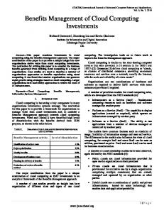
generates events for the first three event generation schemes. The second one (the arrow marked by 2 in Fig. 1) generates schedule based events or instant manual events. For example, during the first time deployment of an application, one can instantly trigger a startup event to change the application state from inactive to active. Similarly, a shutdown event should be triggered to stop and change the application state from active to inactive. The third source of events falls within a different domain. For example, the application owner may have their own event generation scheme and monitoring subsystem that directly feed events into the Controller. 2) Optimization Phase: After receiving an event, the Controller initiates the optimization phase. Application Repository already maintains a list of workflows along with the mapping between events and workflows for every application (as described in the formal definition of the application). Besides, the received events contain certain information which help to decide the optimization procedure. Based on this information, the Controller generates a workflow sequence containing a list of target workflows along with the information of synchronous and asynchronous invocation. The Controller then kicks off (starts) the target workflows according to the generated workflow sequence. Thus, the key to this phase is the implementation of various optimization workflows. Along with autoscaling, Application Centric Cloud also provides a cost effective fault tolerant mechanism to the deployed application. Thus the various events generated by the monitoring subsystem can roughly be classified into two categories - scaling events and recovery events. Accordingly, workflows can also be categorized as recovery workflow and scaling workflow. The recovery workflows are easy to implement compared to the scaling workflows. This is because a recovery workflow just requires to restart a service or relaunch a new VM replacing a failed one. These workflows provide a cost effective fault tolerance mechanism to the deployed application. However scaling workflows require implementation of much more complex actions. It is possible to scale the resources either vertically or horizontally. With vertical scaling, the capacity of a particular resource is increased or decreased, whereas with horizontal scaling, similar resources are added or removed from a particular tier. The sequence diagram for vertical scaling workflow is shown in Fig.2 considering Amazon EC2 as the infrastructure provider. Once the Controller receives a scaling event, it retrieves the IP and AMI (Amazon Machine Image) information from the event. It then decides the instance type [15] of the VM to be launched based on the direction and amount of scaling. Once the new VM is launched, it then migrates the ongoing sessions to the new VM. All the EBS (Elastic Block Storage) [16] volumes are also moved to the new VM. Finally the global IP (Elastic IP) is assigned to the new VM and the old VM is terminated. During the workflow execution, session migration action must be carried out synchronously with instance launching action. However, actions related to associating EBS and associating global IP can be invoked asynchronously once the new VM is launched. Terminating instance action must also
Fig. 2.
Sequence diagram of Vertical Scaling Workflow
be invoked synchronously with obtaining EBS list action. Considering all these actions and their dependencies, the Controller forms a workflow sequence and invokes the actions accordingly. Horizontal scaling workflow is easier to implement compared to vertical scaling workflow. Horizontal scaling workflow needs the tier or resources to be deployed with a load balanced cluster [17]. Once the Controller receives a scaling event, it decides the amount and direction of scaling based on the information retrieved from the event. Accordingly, it either launches or terminates some of the VMs and reconfigures the corresponding cluster. IV. I MPLEMENTATION AND E VALUATION The Application Centric Cloud architecture proposed by us has been implemented with Xen as the virtualization technology, Amazon EC2 as the public cloud provider, Eucalyptus as the private cloud provider and Zabbix as the monitoring and feedback control system. We have tested the implementation with a php based online collaboration system, Php-Collab. The Php-Collab application is deployed with three tiers (T) namely web tier, application tier and database tier (refer to the formal definition as discussed in Section III). The web tier is implemented with apache load balancer nodes as the resources (R). They balance the loads to the application tier. The application tier is implemented with php-collab nodes and the database tier is implemented with mysql cluster nodes as the resources. We define two events (E) namely app-tieroverloaded and app-tier-underused for the application tier and a single event app-tier-server-died for application tier nodes. The events app-tier-overloaded and app-tier-underused map to scale up and scale down workflow respectively. The event apptier-server-died maps to the recovery workflow. The scale up and recovery workflow launches a new VM in the application tier, configure php-collab in the new VM and reconfigures load balancer in the web tire. The scale down workflow just reconfigures the load balancer in the web tire. Open
Symphony Workflow Engine [18] has been used to implement the workflows for various events. Metrics shown in Table I have been used for generating events. In Zabbix, ’Item’ collects the data for the above metrics. Zabbix has already defined items for most of the metrics. However, in order to collect aggregated data for a metric from a number of resources, we need to create an aggregated item in Zabbix. Thus, for tier level events (refer to formal definition of an application) we have created triggers with aggregated items, whereas for resource level events we have created triggers with non-aggregated items which are already defined by the Zabbix. Creation of triggers with aggregated items is difficult in comparison to the non-aggregated items. The algorithm for creating such a trigger with aggregated items is given bellow: i) Create a Host Group named ‘HG’ containing all the instances(VMs). ii) Create an Aggregated Item named ‘HG Item’ with key like grpavg[‘HG’, ‘’, ‘’, ‘300’]. It will collect aggregated (defined by aggregate function) data for the metric. iii) Create a Trigger named ‘HG Trigger’ with expression like {ZABBIX Server : grpavg[‘HG’, ‘’, ‘’, ‘300’] > threshold}. Here the Zabbix server itself collects the aggegated data on behalf of ‘HG’ and triggers a Zabbix event whenever the collected data exceeds a threshold. iv) Create an Action named ‘HG Action’ with conditions matching the trigger name as ‘HG Trigger’ and trigger value as ‘PROBLEM’. The operation for the action includes notification to the Controller through an application event with proper information regarding the Zabbix event. The hysteresis ( i.e. unnecessary triggering of events ) is considered by setting the trigger value as ‘PROBLEM’. Thus, an event is triggered only when the trigger changes its state to ‘PROBLEM’. An event filtering mechanism has also been implemented in the Controller in order to filter out some of
TABLE I M ETRICS ( ZABBIX ) FOR E VENT G ENERATION Metric
Key
Ping to server (TCP)
agent.ping
Host Status
status
CPU Utilization
system.cpu.util[,user,avg1]
Bandwidth
net.if.in[eth0,bytes] net.if.out[eth0,bytes]
Memory
vm.memory.size[free] system.swap.size[,free]
Apache Request
apache.reqpersec Fig. 4.
Overhead graph for php-collab application
invoked with the actions for provider, the Provider Time is small - just the time required to invoke the corresponding web service. The performance data for the php-collab application is also tabulated in Table III and is shown graphically in Fig. 5. TABLE III P ERFORMANCE DATA FOR PHP - COLLAB APPLICATION Input Load
Fig. 3.
Php-collab Application during Scale Up
the unnecessary events. For schedule based event generation scheme we have used EJB session bean Timer. The state of the php-collab application during the execution of a scale-up workflow is shown in Fig. 3. In order to evaluate the Application Centric Cloud architecture with the above mentioned php-collab application we have run our implementation in a Desktop PC with Intel Core 2 Duo 2GHz Processor, 1GB RAM & standard dialup network connection. The overhead for automation used within the cloud application is tabulated in Table II and is shown graphically in Fig. 4. TABLE II OVERHEAD DATA FOR PHP - COLLAB Event
APPLICATION
Application Load
No. of VMs
5
5.16
1
10
10.22
1
15
15.30
2
15
8.15
2
20
10.89
2
30
15.95
3
21
7.86
3
35
13.07
3
20
7.6
3
11
4.72
3
9
3.02
2
9
4.61
2
20
11.23
2
40
22.32
3
40
14.89
3
50
18.53
4
50
13.78
4
70
19.34
5
35
9.03
5
4
1.67
4
Provider Time (in seconds)
Overhead Time (in seconds)
Total Time (in seconds)
4
2.01
3
4
2.56
2
Startup
476.89
424.82
901.80
4
4.38
1
Scale Up
179.58
154.83
334.41
0
0.03
1
6.99
107.60
114.59
Instance Recovery
156.68
139.96
296.64
Service Recovery
7.12
14.14
21.26
Shutdown
32.34
14.44
56.78
Scale Down
In Table II, Provider Time is the time the Controller waits for the Provider to return. The Overhead time is the remaining time to complete the workflow. Since various actions for scaling down and service recovery events are asynchronously
We have used threshold based event generation scheme and processor load metric for the performance evaluation. We have observed that 15 units of processor load reasonably overloaded the application and the resources are under used for a processor load of 4 units or less. So we have defined the thresholds accordingly. We have simulated the input load in such a way that 1 unit of input load generates approximately 1 unit of application load if the application tier cluster contains a single
feature of cloud environment and the flexibility of workflow based programming to implement its functionality. R EFERENCES
Fig. 5.
Performance graph for php-collab application
node. With these considerations, the performance graph shows that the application load tries to remain within the range of 4 to 15 units even though the input load varies from 0 to 70 units. V. F UTURE W ORK The performance of the architecture in terms of stability in application loads as compared to the input load variation depends on proper configuration of various event generation schemes and parallelism in the implementation of various workflows. In future further investigation will be carried out for better event generation schemes and the implementation of various workflows, in particular for vertical scaling. The Application Centric Cloud will fail to optimize the cost in presence of hysteresis i.e. unnecessary triggering of events. For example if someone chose the event generation scheme wrongly it may happen that a scale up event will eventually trigger a scale down even and that scale down event will eventually trigger a scale up event. Such scale up and scale down will continue for ever as an effect of each other. With hysteresis the overall cost will be increased even if the application load remains stable. In future we want to investigate more for the detection and recovery of such hysteresis. VI. C ONCLUSION We are not far way from the day when we will see that most of the servers are physically installed only at the data centers and most of the medium scale and startup organizations will consist of only desktops and access or deploy their large scale applications on the rented virtual servers from the data centers. With such virtual environment, it will become critically important to monitor and optimize the use of such virtual resources and thereby reduce the cost and provide scalability and availability to the deployed applications. Application Centric Cloud architecture provides a generalized framework for managing the resources provisioned for a deployed application and automatically optimizes the cost considering the loads and failures of various resources. Application Centric Cloud utilizes the on demand availability
[1] A. Desai, Definitive Guide To Virtual Platform Management, Realtime Publishers, 2007. [2] G. Sheild, Selecting the Right Virtualization Solution, Realtime Publishers, 2007. [3] R. Buyya et al, Modeling and Simulation of Scalable Cloud Computing Environments and the CloudSim Toolkit: Challenges and Opportunities, In Proceedings of the 7th High Performance Computing and Simulation (HPCS 2009) Conference, Germany, June 21 - 24, 2009 [4] D. Abramson, R. Buyya and J. Giddy., A computational economy for grid computing and its implementation in the Nimrod-G resource broker, Future Generation Computer Systems 18, 8 (2002), 1061 - 1074. [5] S. Garfinkel, An Evaluation of Amazons Grid Computing Services: EC2, S3 and SQS, Tech. Rep. TR-08-07, Harvard University, August 2007. [6] J. Dean and S. Ghemawat, Mapreduce: Simplified data processing on large clusters, In ACM,51(1):107-113, 2008. [7] I. M. Llorente, R. S. Montero, E. Huedo and K. Leal, A Grid Infrastructure for Utility Computing, In WETICE ’06, 15th IEEE International Workshops on Infrastructure for Collaborative Enterprises. [8] R. Wolsky et al, Eucalyptus: A Technical Report on an Elastic Utility Computing Archietcture Linking Your Programs to Useful Systems, Tech. Rep. 2008-10, University of California, Santa Barbara, October 2008. [9] Open Nebula. Available from: http://www.opennebula.org/documentation:faq [10] Amazon EC2 Auto Scaling, Cloud Watch and Elastic Load Balancing. March 2009. Available from: http://aws.amazon.com/autoscaling/, http://aws.amazon.com/cloudwatch/ http://aws.amazon.com/elasticloadbalancing/ [11] Flexiscale Public Cloud Provider. Available from: http://www.flexiscale.com [12] GoGrid Public Cloud Provider. Available from: http://www.gogrid.com [13] P. Padala et al, Adaptive control of virtualized resources in utility computing enironments, In Proceedings of EuroSys, 2007. [14] H.C.Lim et al, Automated control in cloud computing: challenges and opportunities, In Proceedings of the 1st workshop on Automated control for datacenters and clouds, Spain, June 19, 2009. [15] Amazon EC2 Instance Types. April 2008. Available from: http://aws.amazon.com/ec2/instance-types/ [16] Amazon Elastic Block Storage. April 2008. Available from: http://aws.amazon.com/ebs/ [17] Approaches to load balanced clusters. Available from: http://onjava.com/onjava/2001/09/26/load.html [18] Open Symphony Workflow Management System. Available from: http://www.opensymphony.com/osworkflow/ [19] A. Savitzky and M.J.E. Golay, Smoothing and Differentiation of Data by Simplified Least Squares Procedures, In Analytical Chemistry, 36 (8): 1627-1639. [20] Mills and C. Terence, Time Series Techniques for Economists, Cambridge University Press, 1990.