REVIEW OF SCIENTIFIC INSTRUMENTS
VOLUME 72, NUMBER 8
AUGUST 2001
Application of a multichannel detection system to the high-resolution fast electron energy loss spectrometer Xiao-Jing Liu, Lin-Fan Zhu, Xi-Man Jiang, Zhen-Sheng Yuan, Bei Cai, Xiang-Jun Chen, and Ke-Zun Xua) Open Laboratory of Bond Selective Chemistry, Laboratory of Atomic and Molecular Physics, University of Science and Technology of China, Hefei, Anhui 230027, People’s Republic of China
共Received 27 November 2000; accepted for publication 4 April 2001兲 A microchannel-plate based resistive-anode position sensitive detection system is applied to a high-resolution fast electron energy loss spectrometer. The biasing voltage divider network for the detector is investigated. The measurement efficiency is increased by about 20 times, and to some extent, the energy resolution is also improved. The static mode and the scanning mode of the spectrometer are discussed in detail. In the scanning mode, a spectrum with higher energy resolution can be obtained through a coarse scanning. As a testing experiment, the optical oscillator strength spectrum for the Rydberg series of helium is measured and the results are compared. © 2001 American Institute of Physics. 关DOI: 10.1063/1.1382636兴
high energy resolution,11 or the electron momentum spectrometer with medium incident energy and low energy resolution.12 In this article, it was applied to a high resolution fast EELS,9 and the calibration and performance are stringently tested.
I. INTRODUCTION
Since introduction of microchannel-plate 共MCP兲 in the early 1960’s, it has been widely used to detect photons, electrons, ions, and neutral atoms,1– 4 the electrons ejected from MCP provide the position information of the incident particles,5 therefore, MCP is frequently used in the position sensitive detector 共PSD兲.6 The high-resolution fast electron energy loss spectrometer 共EELS兲 is one of the most powerful instruments to obtain the excitation information for atoms and molecules.7–9 Because the incident electron energy used in this spectrometer is much higher than the transition energy, and the momentum transfer is very small at scattering angle of 0°, and hence it is equivalent to photoabsorption procedure without the limitation of ‘‘line saturation’’ effect,8 so the optical oscillator strength can be obtained. In addition, the generalized oscillator strengths for the excitations can be measured at nonzero momentum transfer but at the meaningful region of large momentum transfer, the cross section is very small, so it is urgent to boost the efficiency of the spectrometer for further study. In this spectrometer, two electrostatic hemispherical deflection analyzers 共SDA兲 are used separately for electron energy monochromatization and analysis. When a SDA is used for electron energy analyzing, a linearly energy-dispersed image is formed along a radial exit slit, which could be detected by a PSD.10 Using this method of parallel data acquisition, compared with a single-channel acquisition method, the time required to accumulate enough data to give significant atomic structure and scattering information is greatly reduced, of course there must be stringent tests of the calibration and performance of the electron spectrometers and detector. The MCP based PSD has been widely used in the electron energy loss spectrometer with low incident energy and
II. SPECTROMETER
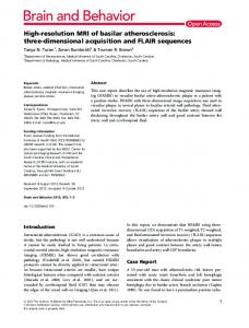
The electron energy loss spectrometer and PSD assembly are shown schematically in Fig. 1. It consists of an electron gun, an electrostatic hemispheric monochromator made of aluminum with a center radius of 200 mm, a rotatable analyzer of the same type, a MCP-based resistive anode PSD with a front slit, an interaction chamber, a number of cylindrical electrostatic optical lens. All these components are enclosed in four vacuum chambers. In the earlier setup,9 the electron was detected by a channeltron behind the exit aperture of the energy analyzer and the diameter of the aperture was 1 mm. In this setup the aperture is replaced by a 24 mm long and 1 mm wide slit, with this modification, we can collect many spectral elements simultaneously, and the experimental time is reduced by more than 20 times. Therefore, measurements are allowed to be extended to regions where signal rates are prohibitively small, this enables to do some new experiments, and permits more stringent tests of existing quantum scattering models. Because the position resolution of the used PSD is about 0.1 mm13 and in the prior setup all electrons passing the aperture are detected nondistinctively, the radial spatial uncertainty of detected electron is also greatly reduced by this modification. For a electron exiting the analyzer, its energy loss E value is determined by its radial position and compensating voltage V, shown in the equation:10 E⫽V⫺
a兲
共1兲
here x is the radial position relative to the central radius R of
Electronic mail:
[email protected]
0034-6748/2001/72(8)/3357/5/$18.00
⑀P x⫺ ⑀ p ␣ 2 ⫽V⫹kx⫹b, 2R
3357
© 2001 American Institute of Physics
Downloaded 08 Oct 2001 to 128.3.132.197. Redistribution subject to AIP license or copyright, see http://ojps.aip.org/rsio/rsicr.jsp
3358
Rev. Sci. Instrum., Vol. 72, No. 8, August 2001
Liu et al.
FIG. 1. Diagram of the EELS spectrometer.
the SDA, ⑀ p is the central orbit energy of the SDA, ␣ is the angle between the electron beam and the tangent of the central orbit in the entrance of the SDA. A. Position sensitive detector
A number of types of PSDs using different methods determining position are available. A MCP based resistive anode PSD is chosen for its simplicity and satisfactory position resolution in this work. The setup of the PSD is shown in Fig. 2. The MCPs used in the chevron configuration were supplied by Nanjing Sunshine Instrument Corp. It has an external diameter of 33 mm, an active area of 26 mm diameter, and an interelectrode resistance of about 100 M⍀. The channels of the MCP have a diameter of 10 m, a separation of 12.5 m, a length-todiameter ratio of 40:1, and a bias angle of 11°. The distance from the slit to the input surface of the first MCP is 6 mm, the width of the interplate gap is 2 mm, and the distance from the output surface of the second MCP to the resistive anode is 5 mm. V t is the voltage between slit and the input face of the MCP chevron that represents the impact energy of the electrons. V M is the biasing voltage on single MCP. V p is the voltage between the two MCPs in the chevron that accel-
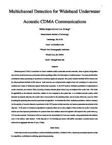
FIG. 2. Voltage supply and signal process circuit of the position sensitive detector. A and B refer to the two signals from the two ends of the resistive anode strip. V 1 represents the impact energy of the electrons: V M is the biasing voltage on single MCP; V p is the voltage between the two MCPs in the chevron: V A is the voltage between the chevron pair and the resistive anode.
FIG. 3. Variation of count rate corresponding to each voltage on the detector: 共a兲 variation of count to the biasing voltage V M on MCP; 共b兲 variation of count to the electron impact voltage V I ; 共c兲 variation of count to the interplate voltage V p between the two MCPs; 共d兲 variations of count to the voltage V A ; 共e兲 variation of count to the total voltage on the detector as V I ⫽2V M ⫹V P ⫹V A , which has a ratio of V M :V P :V A ⫽10:0.55:4.
erates the electrons ejected from the first MCP. V A is the voltage between the chevron and the resistive anode that accelerates the electrons ejected from the second MCP. The charge cloud produced by the MCP chevron is collected by the resistive anode strip, which is divided into two parts of A, B at the two ends of the anode strip. Both signals of A and B are amplified and shaped, then converted to digits by two 12-bit ADCs. The ratio of (A⫺B)/(A⫹B) is proportional to the position x mentioned above.14,15 A separate nanosecond rise-time fast signal is decoupled from MCP chevron through a pulse transformer, then converted into a NIM signal that serves as the enabling signal of ADC through a constant fraction discriminator 共CFD兲. The CFD also serves as the filtering stage to remove noises. This method determines the center of gravity of the charge cloud, which is a good approximation to the position of the impact electron. The count rate of the fast signal as a function of each voltage is examined on the conditions that the other voltages are set to suitable values, as seen in Fig. 3. In Fig. 3共a兲, a plateau is reached when V M rises to 1000 V. In Figs. 3共b兲– 3共d兲, when V M is increased, the plateaus for V l , V P , and V A become more obvious and can be reached at smaller values. In Fig. 3共b兲, for V M ⫽1000 V, the plateau is reached when V l
Downloaded 08 Oct 2001 to 128.3.132.197. Redistribution subject to AIP license or copyright, see http://ojps.aip.org/rsio/rsicr.jsp
Rev. Sci. Instrum., Vol. 72, No. 8, August 2001
rises to 300 V. Muller et al.2 observed that absolute detection efficiency decreased as the impact energy rose to 200 eV, while they did not give more information of their detector. In Fig. 3共c兲, for V M ⫽1000 V, a plateau is reached as V P rises to 50 V. Rogers et al.16 also showed that the gain of the MCP chevron was increased with increasing V P . Although frequently the output surface of the first MCP is directly connected to the input surface of the second MCP, it would be better to place an suitable interplate voltage between them. In Fig. 3共d兲, a plateau is reached as V A rose to 300 V for V M ⫽1000 V. When V A is 0 V, the count rate is always zero. This phenomenon might be ascribed to the space charge repulsion effect, since the second MCP produces a large number of secondary electrons, they might distort the local electric field at the rear end of the channels of the second MCP, the secondary electron ejection might be restrained, then the pulse height of the fast signal is reduced. It might also explain that the count increases with increasing V P . As shown in Fig. 2, a voltage divider network is designed, the total voltage V T ⫽2V M ⫹V P ⫹V A with ratio of V M :V P :V A ⫽10:0.55:4 is placed on the overall network, a plateau is reached as V T rises to 2500 V. B. Operation modes of the apparatus
The electron energy loss spectrometer can be operated in a static or a scanning mode. In the static mode, the compensating voltage V is fixed, the electron energy loss spectrum is determined only by the distribution of the electrons at the different positions on the resistive anode strip. The separation energy range covered by the PSD is about 1.5 eV. In order to obtain a correct knowledge of spectrum, it is indispensable to test the position-dependent efficiency of the PSD. On the other hand, in the scanning mode, the compensating voltage V is scanned across the interesting excitation energy range at the step width of ⌬V, the electron energy loss is determined by both the position and the compensating voltage as shown in Eq. 共1兲. As the ADCs used are very precise and the height of the signals of A or B has an approximate Gaussian distribution,16 it is convenient to regard E as a continuous value, the spectrum can be given as a collectivity of spectral elements of width ⌬E. The deviation of the efficiency for different energy loss points would be reduced in this mode, which will be discussed in Sec. III.
Multichannel EELS
3359
FIG. 4. Example of an electron energy loss spectrum measured in the static mode: Rydberg series of He n 1 P(n⫽4 – 8)←1 1 S.
measured as shown in Fig. 4. The excitation energies of the discrete peaks as a function of their positions are plotted in Fig. 5共a兲, for which the linearly fitted regression coefficient is 1.315⫾0.005. In the scanning mode, the compensating voltages as a function of the positions of a discrete peak, for the transitions 2 1 P←1 1 S of He, are shown in Fig. 5共b兲, for which the linearly fitted regression coefficient is ⫺1.313 ⫾0.009. For both modes, the same value and opposite sign 关because of E and V in Eq. 共1兲兴 of these two regression coefficients show excellent energy dispersion linearity.
B. Detection efficiency
To get an correct electron energy loss spectrum, the uniformity of the detection efficiency for each energy loss point should be small enough within the frequently required statistical error of 3%. In the present measurement, the deviation of the detection efficiency of PSD from unity could be ascribed to four factors. First, the practical electrostatic field distribution in the spectrometer is always different from an idealized one, its effects can be minimized by careful adjustment of the electron-optical system. Second, gain depression can occur at count rates of the order of 1 count channel channel⫺1 s⫺1 for MCPs,17 when there are excessive elec-
III. CALIBRATION
A spatial mask could be installed in front of the PSD chevron to test its linearity and position-dependent efficiency, but in routine operation, it is impractical and difficult to separate the influence on the measured spectrum produced by the hemispherical analyzer and the PSD. Therefore, a suitable way is to examine the influence caused indicated below. A. Energy dispersion
An electron energy loss spectrum, which contains distinctive features, was measured in both modes. In static mode, the Rydberg series n 1 P←1 1 S (n⫽4 – 8) of helium is
FIG. 5. Energy dispersion for the hemispherical and PSD: 共a兲 static mode, 共b兲 scanning mode. Due to the equation: E⫽V⫹k x ⫹b, the linear coefficients obtained from these two modes have the opposite sign.
Downloaded 08 Oct 2001 to 128.3.132.197. Redistribution subject to AIP license or copyright, see http://ojps.aip.org/rsio/rsicr.jsp
3360
Liu et al.
Rev. Sci. Instrum., Vol. 72, No. 8, August 2001
FIG. 6. Deviation of relative efficiency for each energy loss point from unity: 共a兲 static mode; 共b兲 scanning mode, the width of spectral element ⌬E is chosen flexibly as (e⌬V)k,(k⫺8,4,2,1).
trons getting into the pores of MCP, the charge lost caused by electron multiplying cannot be replenished in time, so the output signals will decrease. It means that a stronger peak might cause more serious gain depression than a weaker one. In the present measurement, the count rates are controlled under the order of 0.1 count pore⫺1 s⫺1, so the influence of gain depression is avoided. Third, the resistive surface coating on the MCP causes spatially dependent dissipation effect on the fast signal,12 thus it affects the spatial uniformity of information derived from the fast signals. In the present setup, the amplitude of the fast signal is about 150 mV, and the discrimination threshold level of the CFD is set at 50 mV, it ensures that almost all of the true signals have been recorded. Finally, the aging effect is frequently different for a section of MCP, usually it can be reduced by increasing biasing voltage. In the static mode, the relative detection efficiencies for the energy loss points are directly derived from the relative detection efficiency of PSD. Two methods were performed to test the uniformity of the relative detection efficiency for the PSD. In the first method, a smooth electron energy loss spectrum in the continuum region, such as one located about 10 eV above the first ionization threshold of helium, is measured in the static mode. The relative detection efficiency could be obtained by comparing it with another one measured in the scanning mode, which is regarded as standard. The deviation of the relative detection efficiency from unity for the PSD is less than 3% as shown in Fig. 6共a兲. The second method was performed in conjunction with the energy linearity test described above. The relative detect efficiency is obtained by recording the area of a discrete peak as a function of the corresponding position. Unlike a discrete
FIG. 7. Optical oscillator strength distributions for discrete valence shell of He: Rydberg series of He n 1 P(n⫽2 – 8)←1 1 S.
spectrum, a continuous one is hardly influenced by the energy resolution, so the result of the first method would be more accurate. Frequently, the large deviation of the relative detection efficiency could be minimized by the adjustment of the electron-optical lenses shown in Fig. 1. In the scanning mode, the energy loss E is derived from the measured position x and the compensating voltage V according to Eq. 共1兲. The energy loss range covered by PSD is set as E d ⫽Ne⌬V, and the width of spectral element is set as ⌬E⫽e⌬V/k,E d is divided into N⫻k chips and with width of ⌬E, the relative PSD detection efficiency is (i) (i ⫽0,1,– ,N⫻k⫺1) then the relative detection efficiency of the jth energy loss point can be written as
⬘共 j 兲 ⫽
N⫺1 兺 i⫽0 共 m⫹k⫻l 兲
N
共2兲
,
where m⫽mod( j,k)⫽ j⫺k⫻Int( j/k). The relative detection efficiency is partially averaged, so its variation will be reduced as shown in Fig. 6共b兲. Because ⌬V is 0.08 V, the width of the range of the energy loss covered is 1.44 eV. Deviation of the relative efficiency from unity at ⌬E/(e⌬V)⫽1/8 is reduced by 24 times. It can be further reduced as ⌬E/(e⌬V) increases, and eliminated as ⌬E/(e⌬V)⫽1. Although the measurement would not be affected by variations of position-dependent detection efficiencies of the PSD if the spectral element width ⌬E is equal to the scanning step width e⌬V. 18 If the range of the interesting energy is scanned in the coarse step of ⌬V, an energy spectrum with higher resolution can also be obtained without to some extent, sacrifice of uniformity of relative detection efficiency.
TABLE I. Absolute optical oscillator strengths for transitions of n 1 P←1 1 S for helium. Reference
21P
31P
41P
51P
61P
71P
81P
This work
0.280 共0.0007兲 0.280 0.280
0.0748 共0.0005兲 0.0741 0.0745
0.0304 共0.0005兲 0.0303 0.0303
0.0153 共0.0005兲 0.0152 0.0153
0.0090 共0.0005兲 0.00892 0.00907
0.0059 共0.0005兲 0.00587 0.00595
0.0042 共0.0014兲
8 19
Downloaded 08 Oct 2001 to 128.3.132.197. Redistribution subject to AIP license or copyright, see http://ojps.aip.org/rsio/rsicr.jsp
Rev. Sci. Instrum., Vol. 72, No. 8, August 2001
Compared with the static mode, the offline data process for the scanning mode would be greatly simplified. Because the scanning range of the compensating energy should be the sum of the spectral range of interest and the PSD-spanned energy range, the duty cycle is reduced, and it increases as the spectral range of interest increases. For an experiment the operation mode is chosen according to the spectral range of interest. If it is wider than 1.5 eV, the scanning or static mode would be preferred.
Multichannel EELS
3361
ACKNOWLEDGMENTS
The authors thank Professor X. Q. Yu and Dr. T. Yang for their great help in solving electronics problems. This work was supported by National Nature Science Foundation of China 共19634040兲, by The Research Foundation for the Doctoral Program of Higher Education 共97035806兲, and The Youth Foundation of The University of Science and Technology of China. J. L. Wiza, Nucl. Instrum. Methods 162, 587 共1979兲; G. W. Fraser, Nucl. Instrum. Methods Phys. Res. A 221, 115 共1984兲. 2 A. Muller, N. Djuric, G. H. Dunn, and D. S. Belic, Rev. Sci. Instrum. 57, 349 共1986兲. 3 H. C. Strub, M. A. Mangan, B. G. Lindsy, K. A. Smith, and R. F. Stebbings, Rev. Sci. Instrum. 70, 4238 共1999兲. 4 M. Barat, J. C. Brenot, J. A. Fayeton, and Y. J. Picard, Rev. Sci. Instrum. 71, 2050 共2000兲. 5 M. L. Edgar, R. Kessel, J. S. Lapington, and D. M. Walton, Rev. Sci. Instrum. 60, 3673 共1989兲. 6 M. Lampton and F. Paresce, Rev. Sci. Instrum. 45, 2098 共1972兲. 7 M. Inokuti, Rev. Mod. Phys. 43, 97 共1971兲. 8 W. F. Chan, G. Copper, and C. E. Brion, Phys. Rev. A 44, 186 共1991兲. 9 S. L. Wu, Z. P. Zhong, R. F. Feng, S. L. Xing, B. X. Yang, and K. Z. Xu, Phys. Rev. A 51, 4494 共1995兲. 10 F. Hadjarab and J. L. Erskine, J. Electron Spectrosc. Relat. Phenom. 36, 227 共1985兲; S. Nishigaki and S. Kanam, Rev. Sci. Instrum. 57, 1469 共1986兲. 11 L. J. Richter and W. Ho, Rev. Sci. Instrum. 57, 1469 共1985兲. 12 D. K. Waterhouse and J. F. Williams, Rev. Sci. Instrum. 68, 3363 共1997兲. 13 C. C. Jia, X. J. Chen, S. X. Tian, Y. G. Ou, and K. Z. Xu, Nucl. Technol. 共in Chinese兲 22, 153 共1999兲. 14 S. Kalbitzer and W. Melzer, Nucl. Instrum. Methods 56, 301 共1967兲. 15 A. Doehring, S. Kalbitzer, and W. Melzer, Nucl. Instrum. Methods 59, 40 共1968兲. 16 D. Rogers and R. F. Malina, Rev. Sci. Instrum. 63, 139 共1982兲. 17 M. L. Edgar, J. S. Lapington, and A. Smith, Rev. Sci. Instrum. 63, 816 共1992兲. 18 H. Shuman and D. Kruit, Rev. Sci. Instrum. 56, 231 共1985兲. 19 R. F. Feng, B. X. Yang, S. L. Wu, S. L. Xing, F. Zhang, Z. P. Zhong, X. Z. Guo, and K. Z. Xu, Sci. China, Ser. A: Math., Phys., Astron. 26, 744 共1996兲. 1
IV. APPLICATION TO AN EXPERIMENT OF ELECTRON ENERGY LOSS SPECTRUM
An electron energy loss spectrum for the Rydberg series n 1 P←1 1 S (n⫽4 – 8), of helium measured in the static mode at the scattering angle of 0° is shown in Fig. 4. A least-square curve fit shows that the energy resolution is 45 meV, which is better than the typical energy resolution of the former apparatus of 60 meV. It might be attributed to the reduction of the uncertainty of the radial position of detected electrons mentioned above. The absolute optical oscillator strength distribution of He measured in the scanning mode at scattering angle of 0° is shown in Fig. 7. The data acquisition time is about onetwentieth of the former. The energy resolution is 55 meV. The deterioration of the energy resolution was caused by the fluttering of the compensating voltage during scanning. The result of the present measurement along with the previous works are shown in Table I. The absolute oscillator strengths of excitation of (2 – 7) 1 P←1 1 S of helium measured in this work agree well with that of Chan et al.8 and Feng et al.19 within experimental uncertainty, in addition, the absolute oscillator strength of excitation of 8 1 P←1 1 S of helium is also reported.
Downloaded 08 Oct 2001 to 128.3.132.197. Redistribution subject to AIP license or copyright, see http://ojps.aip.org/rsio/rsicr.jsp