Design(AD) theory in simple electrical circuits, such as RC and. LC . These
circuits ... Mechanical Engineering at Massachusetts Institute of Technology. (MIT
).
Proceedings of ICAD2006 4th International Conference on Axiomatic Design Firenze – June 13-16, 2006
ICAD-2006-35 APPLICATION OF AXIOMATIC DESIGN THEORY IN ELECTRICAL ENGINEERING Mahmoud Hoshmand
[email protected] Associated Professor, Dept of Industrial Engineering, Sharif University of Technology, Tehran, Iran
ABSTRACT Designers of electrical and electronic devices, especially in one off jobbing production systems, are facing trial and error process to reach an optimum design. This process is a tedious and time consuming. Therefore most of designers are using advanced computer softwares to reduce design activities time but computer softwares still can not solve trial and error process in the design of these devices. For example in the design of filters, high frequency circuits, switching power supplies, antennas and etc the trial and error process to reach the desired design is still the most time consuming process. In this paper, at first we consider application of Axiomatic Design(AD) theory in simple electrical circuits, such as RC and LC . These circuits are selected to show implication and advantage of applying AD theory in a simple manner. Secondly the traditional design process of Tapped Round Rod Combline Microwave Filter (TRRCMF) is reviewed and compared with AD method. The result of this comparison generated a new corollary and presented a high reduction in design cycle time. Keywords: Axiomatic Design, Trial and Error reduction, RC & LC circuit design, Combline Filter Design
1 INTRODUCTION The electrical and electronic systems affected considerable improvement in development of the human life style. Therefore designers are faced with the variety of products to be designed as well as variety of function to be performed by a single product. For example low ripple, minimum power loss, small dimensions, high quality factor and low cost are to be satisfied simultaneously by a filter. These functional requirements may results semi coupled design that requires trial and error to fix design parameters. Such conditions increase design cycle time.
2 AXIOMATIC DESIGN THEORY REVIEW
Copyright © 2006 by ICAD2006
Hamed Farrahi
[email protected] M.S. student in Dept of Industrial Engineering, Sharif University of Technology, Tehran, Iran
In the recent years short Time-to-Market (TTM) is an important strategic weapon for companies that act in a competitive environment. Changing technology, globalization, and demanding customers are amongst others factors that force firms to be innovative [1-5]. The ability to introduce new products more quickly has several potential advantages, such as better quality of design, better product performance, and a higher market share [3]. Therefore, minimizing design cycle time is the most important functional requirement in any electrical system design. The goal of this paper is to reduce the trial & error in design process to get the best performance of the system in short time and low cost. Trail & error process is not due to low specialized skill and knowledge of designers. The main reason of trail & error in design process is the outcome of design parameters setting. Considering interrelation of design parameters, adjusting one design parameter affects previously adjusted design parameter. Therefore designers are facing a loop to adjust design parameters. This process is continued until all the design parameters are set. Pay attention that most of expert designers are applying above procedure. Although, most of them are exploiting advanced computer and softwares to reduce design cycle time, but obviously application of sophisticated software only reduces calculation time not trial and error processes. There are some methods to reduce the complexity of a design process. TRIZ and Axiomatic Design are tow newly developed methodologies to solve design problems. TRIZ is a Russian acronym for The Theory of Inventive Problem Solving that originated from extensive studies of technical and patent information. Axiomatic design theory is new systematic approach to design & manufacturing process. This approach to design and manufacturing was born out of the need to develop the disciplinary bases for fields, and to teach engineering student generalizable knowledge. [1] . The Axiomatic Design (AD) theory has been developed during the 1980s by Nam P. Suh, Head of the Department of Mechanical Engineering at Massachusetts Institute of Technology (MIT).
1/6
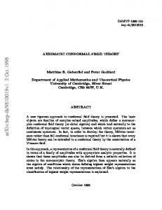
“Application of axiomatic design theory in electrical engineering” 4th International Conference on Axiomatic Design Firenze – June 13-16, 2006 AD is a structured design method created to improve design activities by establishing criteria on which potential designs may be evaluated and by developing tools for implementing these criteria. AD discusses the existence of four domains in the design world: Customer, Functional, Physical and Process domains. See figure 1. Customer attributes {CAs}, functional requirements {FRs}, design parameters {DPs}, and process variables {PVs} are the characteristic vectors of these domains. Design of products involves mapping from the functional domain to the physical domain and design of processes involves mapping from the physical domain to the process domain. Designers follow a design process in which decisions are made about a design object with high level, system decisions and progressing to levels of increasing detail. In following this process to synthesize new designs at each level of detail, the steps through which the designer progresses can be described as a problem formulation, synthesis and analysis. The design axioms provide a tool for evaluating designs, particularly during conceptual design. The two axioms may be stated as follows: The Independence Axiom (Axiom 1): Maintain the independence of the FRs. Alternative statement: In an acceptable design, the DPs and the FRs are related in such a way that specific DP can be adjusted to satisfy its corresponding FR without affecting other functional requirements. The Information Axiom (Axiom 2): Minimize the information content of the design. Once a set of FRs has been formulated and possible sets of DPs have been generated, the two design axioms are used to evaluate the proposed designs (the design axioms can also be applied to analyze relationships between DPs and PVs). Independence axiom states that, during the mapping process from the FRs in the functional domain to the DPs in the physical domain, a change in a particular DP must affect only its referent
Customer Need {CNs}
Functional Requirement {FRs}
Design Parameter {DPs}
Customer Domain
Functional Domain
Physical Domain
Process Variable {PVs}
Process Domain
Figure 1. Design process mapping
the specific design goals constitutes a vector {FRs} in the functional domain. Similarly, the set of design parameters constitutes a vector {DPs}. The relationship between these two vectors can be written as:
[FR ] = [A ][DP ] Aij =
(1)
∂FR i ∂DP j
(2)
where [A] is defined as the design matrix that characterizes the design and shows the relationships between the FRs and DPs at a given level of the design hierarchy. There are two special cases for the design matrix: the diagonal matrix where all Aij’s except those i=j are equal to zero, and the triangular matrix where either upper or lower triangular elements are equal to zero as shown below. ⎧ FR11 ⎫ ⎡ X ⎪ FR 21⎪ ⎢ 0 ⎪ ⎪ ⎢ ⎨ ⎬= ⎪FR 22⎪ ⎢ 0 ⎪⎩ FR31⎪⎭ ⎢⎣ 0
0 X
0 0
0 0
X 0
0 ⎤ ⎧ DP11 ⎫ 0 ⎥⎥ ⎪⎪ DP 21⎪⎪ ⎨ ⎬ 0 ⎥ ⎪ DP 22⎪ ⎥⎪ X ⎦ ⎩ DP31⎪⎭
Uncouple Design ⎡X ⎢0 ⎢ ⎢0 ⎢ ⎣X
0
0
X X
0 X
0
X
0⎤ 0 ⎥⎥ 0⎥ ⎥ X⎦
Decoupled
⎡X ⎢0 ⎢ ⎢X ⎢ ⎣0
X
0
X
0
0 X
X X
X⎤ X ⎥⎥ 0⎥ ⎥ X⎦
Coupled
Figure 2. Uncoupled, Decoupled and Coupled Matrix Design To satisfy the independence axiom, the design matrix must be either diagonal or triangular. When the design matrix [A] is diagonal, each of the FRs can be satisfied independently by means of one DP. Such a design is called uncoupled design (Equation 3.2c). When [A] is triangular, the independence of FRs can be guaranteed if and only if the DPs are changed in a proper sequence. Such a design is called decoupled design. Any other matrix is known as a coupled design. In these equations, an X represents a strong effect by a DP on a FR, while a zero indicates a weak effect, relative to the tolerance associated with the FR.
3 LOW PASS FILTER DESIGN USING AD THEORY Low pass filter circuit is shown in figure 3. The circuit consists of one Resistance and one Capacitor [7].
FR. According to the information axiom, among all the feasible designs that satisfy the independence axiom, the one with the minimum information content is the best design. The mapping process between the domains can be expressed mathematically in terms of the characteristic vectors that define the design goals and the design solutions. At a given level of the design hierarchy, the set of functional requirements that define
Copyright © 2006 by ICAD2006
Page: 2/6
“Application of axiomatic design theory in electrical engineering” 4th International Conference on Axiomatic Design Firenze – June 13-16, 2006 the circuit. This resistance explains internal resistance of power supply and internal resistance of indicator.
R +
+ Vi
L
Vo
C
+
-
-
C
+
Vi = Vsin(2πft)
R
-
Vo -
Figure 3. Low Pass Filter Circuit Figure 4. Serial LC circuit The goals of circuit design in low pass filters are: f c : Cut frequency PL : Maximum power output losses fc =
PL =
1 2πRC
(1)
2 o
V R
( 2)
Note: Cut frequency in frequency domain is equal to the time constant in the time domain. ( τ = 5 * RC ) The design parameters are R and C For uncouple design tow FRs (goals) should be satisfied independently. According to AD theory, design equation of the circuit is as follow:
This circuit is a type of Band Pass Filter. The design requirements of this circuit consist of central frequency ( f c ) and Quality factor ( Q ); Q = f c / ∆f . Therefore the FRs of the circuit design are f c and Q and the design parameters to satisfy FRs are L and C : fc =
1 2π LC
(3)
Q=
1 L R C
(4)
The output power loss of this circuit depends only on R .The output power loss is considered as a constrain. The design equation for this circuit is as follow: [ FR] = A [ DP]
[ FR] = A [ DP] ⎡ PL ⎤ ⎡ X ⎢ f ⎥ = ⎢X ⎣ c⎦ ⎣
According to AD theory, this design is a decoupled design. Therefore, PL is the first parameter that should be set by suitable R value. Then to adjust the f c value, specify the C. In traditional design of such filters maximum power output losses ( PL ) are generally forgotten by designer. AD theory shows its merits in consideration of all goals and produce the design steps. As shown in this simple example, the AD theory, generates a rational and transferable procedure. Therefore, It may be thought straight forward. In this paper firstly the simple examples are discussed. These examples are LC & RC circuits’ design that any electrical engineer is facing them frequently. Then AD theory is applied in a real world situation.
4 SERIAL LC CIRCUIT DESIGN USING AD THEORY Figure 4 shows a serial LC circuit; consist of one Capacitor and one Indicator. To realize the real circuit a Resistance is added to
Copyright © 2006 by ICAD2006
⎡ fc ⎤ ⎡X ⎢Q ⎥ = ⎢X ⎣ ⎦ ⎣
0 ⎤⎡R⎤ X ⎥⎦ ⎢⎣C ⎥⎦
X ⎤⎡ L⎤ X ⎥⎦ ⎢⎣C ⎥⎦
As it can be seen the design matrix is a coupled design. The general solution for these problems is to fix one parameter and calculated another parameter .For example in this circuit L or C is fixed as a specific value and then other parameters are calculated. Electrical engineers are using is concurrent calculation of equations (3) and (4). Namely by multiplying tow sides of equation (3) by L, L value is calculated. This method computes the L and C value without trial & error. But the minimum variation applied to f c or Q affects all design parameter; FRs are depended to each other. Now if we want to solve this problem with AD theory the design matrix should be converted to diagonal or triangular design matrix. To satisfy this condition it is required to change DPs. Thus new DP’s should be defined. The new DP’s may be as follow: DP1=
1 LC
and DP2=
L C
, and the modified design matrix and
design equation is as follow:
Page: 3/6
“Application of axiomatic design theory in electrical engineering” 4th International Conference on Axiomatic Design Firenze – June 13-16, 2006
⎡ f c ⎤ ⎡ 1 2π ⎢Q ⎥ = ⎢ 0 ⎣ ⎦ ⎣
0 ⎤⎡ ⎢ 1 ⎥ R⎦ ⎢ ⎣
1 LC L C
⎤ ⎥ ⎥⎦
Step 4: If the gap value is reasonable value to fabricate the filter, then the design process is completed. If not, go to step 5. Expert experiences show that the gap value tolerances is high and not applicable for fabrication of rods/ wall cavity.
(5)
Considering equation 5, f c may be satisfied with the parameter of(
1 LC
L C
) without any effects on Q , also (
) may be adjusted
to satisfy its corresponding FR, that is Q without any effects on f c . But we are facing a new problem,
1 LC
and
L C
, design
parameters are nonexistence physical elements. Pay attention that the electrical engineers are faced with these parameters (
1 LC
&
L C
) frequently, they are basic parameters in electrical
circuits. Therefore if we can realize physical substances for these parameters then we can make a great evolution in electrical circuits design. In this example AD offers only tools that should be invented in future and shows a way for creative design.
Figure 5: Top structure of Tapped Round Rod Combline Microwave Filter
5 TRRCM (TAPPED ROUND ROD COMBLINE MICROWAVE FILTER FILTER) DESIGN USING AD THEORY One of the most common types of microwave filter is Combline filter using round rod resonators which gives good performance from the UHF region more than 10GHz. Although this filter has been in use more than 40 years, they are still a number of uncertainties on design and manufactures of such filters [9]. Design process of this kind of filters involves high trial & error. One of the merits of TRRCMF (Tapped Round Rod Combline Microwave Filter) is using one capacitor to each resonator. It reduces the filter dimensions; therefore this type of filter may be adopted for low frequency simply. In the design of this type of filter, the capacitor realized with the gap between rod (resonator) tip and wall cavity, figures 5 and 6, [6], [8], [9]. The current design algorithm to design TRRCMF is showed in figure 7. The steps of this algorithm are: Step1: (i) Set the resonator length, l , according to electrical length, θ , ( l < λ 4 , λ is wave length) and (ii) cavity dimension base on design requirement such as f c , BW . Step 2: Calculate the gap value according to the resonator length and height of cavity. In this step gap value is specified with high accuracy. Step 3: Calculate the other DPs according the gap value such s0 , si , Tap . (Tap : Dis tan ce between input / output location to cavity wall
Figure 6. Structure of Tapped Round Rod Combline Microwave Filter (n=4)
Step 5: Round the gap value according to fabrication practices. Step 6: Recalculate the f c , BW according to new gap value. Step 7: Modify the f c by increasing the resonator length. Note: consider the variation of f c ( ∆f c ) Step 8: Check filter’s dimension. Note: any increases on resonator length increases the cavity dimensions and reduces Band Width, BW . Considering that one of the main goal of the filter design is its small dimensions, therefore, the resonator length must be set again and all steps should be repeated again.
s i : Dis tan ce between resonators s 0 : Dis tan ce between resonator & cavity wall )
Copyright © 2006 by ICAD2006
Page: 4/6
“Application of axiomatic design theory in electrical engineering” 4th International Conference on Axiomatic Design Firenze – June 13-16, 2006 Start
and DPs are : l : resonator(rod ) length
Set the resonator length
gap : Dis tan ce between & cavity wall
and cavity dimensions
Tap : Dis tan ce between input / output location to cavity wall
Calculate the gap value gap Fun (l , height of cavity)
si : Dis tan ce between resonators s0 : Dis tan ce between resonator & cavity wall
Calculate s0 , si , Tap
Is the gap value can be fabricated with this tolerances ?
and design equation of this filter is:
Yes
End
No
⎡ Ripple⎤ ⎡ X ⎢ n ⎥ ⎢0 ⎢ ⎥ ⎢ ⎢ fc ⎥ = ⎢ 0 ⎢ ⎥ ⎢ ⎢ B.W ⎥ ⎢ 0 ⎢⎣ R.L ⎥⎦ ⎢⎣ X
0 0 X X X
0 0 X 0 0
0 X 0 X 0
0 ⎤ ⎡Tap ⎤ 0 ⎥⎥ ⎢⎢ gap ⎥⎥ 0 ⎥⎢ l ⎥ ⎥ ⎥⎢ 0 ⎥⎢ S ⎥ X ⎥⎦ ⎢⎣ S 0 ⎥⎦
(6)
Round the gap value
Recalculate fc , BW f c is shifted fc Fun (l , gap) Increases l consider fc
Check filter’s dimensions Cavity dimension is increased and BW is reduced BW Fun (l , gap , si )
Figure 7: Current algorithm used to Design Combline Filter
Now the AD theory is used to optimize the design procedure. Considering independed axiom of the AD theory FRs are defined as follow: f c : Central Frequency B.W : Band Width of Filter
R.L : Maximum Re turn Power Loss n : Filter Order Ripple : max imum var iation of amplitude in the pass band
Copyright © 2006 by ICAD2006
Maintaining selected DPs, it is not possible to convert the design matrix to triangular or diagonal matrix. Therefore, it may be said that the design it is a coupled design. However, the design matrix shows that the gap is an important (critical) DP. This DP affects on f c , BW , R.L , functional requirements. By setting/fixing the gap f c , BW , Ripple and n may be satisfied by only one DP and the design is converted to a semicoupled design. Therefore the design procedure may be modified as follow: Step1: (i) Set the resonator length, l , according to electrical length, θ , ( l < λ 4 , λ is wave length) and (ii) cavity dimension base on design requirement such as f c , BW . Step 2: Calculate the gap value according the l and cavity dimensions. Step 3: Evaluate gap tolerance. In this step, the information content of design is checked, if the information content is low or gap tolerance is suitable for fabrication then calculates s0 , si , Tap and the design is completed. Otherwise go to step 4. Step 4: Increase the fabrication tolerance, that means reduce gap tolerance. Step 5: calculate new l and cavity dimensions according to the new gap. Step 6: Set the other DP such as s0 , si , Tap The new procedure or algorithm developed by AD theory shows an optimum design procedure, see figure 8. In this algorithm trial & error activities are considerably reduced. That means the effort and time to design is reduced efficiently. In practice the outcomes of new design structure developed by AD theory are unbelievable. The procedure was adapted in design of TRRCM filters reduced
Page: 5/6
“Application of axiomatic design theory in electrical engineering” 4th International Conference on Axiomatic Design Firenze – June 13-16, 2006 design cycle time from tow weeks to just only eight hours. That means 93% reduction in design cycle time.
6 NEW COROLLARY: FIXED THE CRITICAL DP Considering the outcome of this study a new corollary may be presented as follow: To convert a couple design to a semicouple design, set the critical DP at first step. The critical DP is the one that has influences on most FRs in design equation. To identify the critical DP in the design matrix select the column that consist of high number of nonzero elements, the related DP to this column is the critical DP, for example column 2 in equation 6. The critical DP in design process should be set at first.
-
Helps designer to review FRs (What?) and DPs (How?) constructively with no ignorance. A rational design is produced; therefore, capability and flexibility of designers are increased due to any variation on customers needs.
8 REFERENCES [1] N.P. Suh, 1990, The Principle of Design, Oxford University Press, 1st edition. [2] N.P. Suh, 2001, Axiomatic Design: Advances and Applications, Oxford University Press, 1st edition. [3] K.Yang and H. Zhang, 2000, A Comparison of TRIZ and Axiomatic Design, Department of Industrial and Manufacturing Engineering, Wayne State University.
Start
[4] D.A .Leonard and N.P. Suh, July 1994, Axiomatic Design and Concurrent Engineering; Computer-Aided Design, Vol. 26 , N 7.
Set resonator length l < λ 4 and cavity dimensions
[5] G.S. Altshuller, 1984, Creativity as an Exact Science, Gordon and Breach Science Publishers.
Calculate the gap value gap = Fun(l , height of cavity )
[6] G. L. Matthaei, L. Young, and E. M. T. Jones, 1980, Microwave Filters, Impedance Networks, and Coupling Structures, Artech House. End
Evaluate the gap value and apply Information Axiom
-
Yes
Calculate s0 , si , Tap
No Increase the fabrication tolerance Reduce gap tolerance
[7] J. Brid, Electrical circuit theory and technology, 2001, Newness Publisher. [8] R. Levy, R. V. Snyder, and G. L. Matthaei, Mar. 2002, Design of Microwave Filter, IEEE Trans. On MMT, Vol. 50, No 3, pp. 783-793. [9] P. Matrin, 2002, Design Equation for Tapped Round Rod Combline and Interdigital Filter, RFShop. [10] RM. Kurzork, Jun 1996, Design of Combline Bandpass Filter, IEEE Trans On MTT, Vol. 14, No. 7, pp 351.
calculate new l and cavity dimensions according to the new gap.
Figure 8: New algorithm of Combline Filter Design base on AD theory
7 CONCLUSIONS AD is powerful concept in design of electrical systems and equipments. Some major benefits of the presented methodology may be as follow: - Reduction of the design cycle time. - Systematic approach on design of electrical systems and devices. - Increased probability of success.
Copyright © 2006 by ICAD2006
Page: 6/6