University of Tennessee, Knoxville, Tennessee 37996-2250. Email: {mmahmoud, jdong, tomsovic, mdjouadi}@utk.edu. AbstractâDuring the past decades the ...
Application of Distributed Control to Mitigate Disturbance Propagations in Large Power Networks Meimanat Mahmoudi, Jin Dong, Kevin Tomsovic and Seddik Djouadi Department of Electrical Engineering and Computer Science University of Tennessee, Knoxville, Tennessee 37996-2250 Email: {mmahmoud, jdong, tomsovic, mdjouadi}@utk.edu
Abstract—During the past decades the electric power infrastructure has evolved into one of the largest and most complex systems due to its extreme dimension, geographic reach and high reliability requirements. Maintaining sufficient security margins requires major enhancement of the existing control. Particular emphasis should be placed on improving the ability of the system to survive extreme contingencies, triggered by very unlikely chains of events, but capable of propagating into widespread outages. In this paper, a distributed control scheme is proposed to mitigate disturbance propagations in large power networks. We find a linear state feedback that simultaneously optimizes a standard Linear Quadratic Regulator (LQR) cost criterion and induces a pre-defined communication structure. The proposed controller provides supplementary damping through the excitation of the generators. The main advantage of this approach lies in the limited communication and limited model information required for the design which makes it practically applicable for large scale systems. We use a large two-dimensional mesh structure test system with homogenous parameters, to demonstrate that the proposed controller performs almost as well as the optimal centralized control with far less amount of communication and computation. The choice of test system is due to the fact that electromechanical wave propagation behavior observed in actual power systems can be readily recognized in that structure.
N OMENCLATURE δi ωi ωs Ef d i Eq0 i E ti fs Hi I di K Ai Pei ,Pmi 0 Td0 ,TAi i VDLQRi Vrefi Xdi ,Xd0 i
Rotor electrical angle, in rad (subscript denotes the ith generator). Rotational speed of the rotor, in rad/s. Base angular speed, in rad/s. Field voltage, in pu. q-axis voltage, in pu. Generator terminal voltage, in pu. Synchronous frequency, in Hz. Inertia constant, in seconds. d-axis current, in pu. Generator excitation gain. Electrical and mechanical power, in pu. d-axis transient time constant and generator excitation time constant, in seconds. Proposed Distributed LQR output, in pu. Reference voltage, in pu. d-axis reactance and d-axis transient reactance, in pu.
I. I NTRODUCTION During the past decades the electric power infrastructure has evolved into one of the largest and most complex systems due to its extreme dimension, geographic reach and high reliability requirements. The highly interconnected structure of the power grid poses a risk of system-wide failures to the network. A local disturbance can influence the system over a wide area and lead to cascading failures and blackouts [1]. On the other hand, larger presence of renewable energy sources and more sophisticated controls throughout the system, will inevitably increase the complexities of the future power grid [2]. These newer devices and controls are introducing new types of instabilities in power systems such as wind farm related oscillations which are difficult to model and monitor [3]. Maintaining sufficient security margins under the threat of multiple unpredictable contingencies, requires major enhancement of the existing control infrastructure. Particular emphasis should be placed on improving the ability of the system to survive extreme contingencies, triggered by very unlikely chains of events, but capable of propagating into costly widespread outages with long-term consequences for both consumers and power companies [4]. Power system engineers have long recognized that disturbances propagate in power network with a finite speed [5]. Different models were developed to capture the spatiotemporal effects of these propagations [5], [6], [7]. These models provide a new understanding of the large scale system dynamics by taking a global view of the problem, while neglecting some of the details in the system behavior [8]. This broader view of the system dynamics can be used to gain valuable insights for designing new control schemes. However, very few studies explored the effects of control design in limiting the widespread propagations [9], [10], [11]. [9] uses disturbance propagation speed to improve power system stabilizers (PSS) performance by introducing an extra damping torque with the disturbance arrival. [10] and [11] employ an impedance matching approach to inhibit reflections of electromechanical waves in power systems. But application of distributed control schemes to mitigate disturbance propagations in large power networks has not yet been studied. Prior to the introduction of real-time phasor measurement units (PMUs), power system control was primarily local.
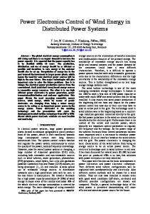
on a generator with its two neighbors. Two generators are considered neighbors if there is a communication link between them. The controller output is the damping signal that goes to the Automatic Voltage Regulator (AVR). Here, it is assumed that the graph of physical layer and communication layer coincide.
Fig. 1. Information exchange between a distributed control agent on a generator with its two neighbors. Two generators are considered neighbors if there is a communication link between them.
Except for the very slowest of controllers and a few specialized schemes, engineers have designed systems largely through local decisions based on local measurements [12]. But, as it is all too apparent during blackouts, power system disturbances may have system-wide impacts. When the information of the entire system is available for the design purpose, centralized control schemes can exhibit a great performance [13]. However, as power networks are large-scale systems, both the synthesis and the implementation of centralized controllers are often impossible in practice [14]. While local controllers are blind to the widespread effects of disturbances and centralized controllers are practically challenging to implement, distributed controllers can achieve a trade-off between performance and required communications. In distributed control, limited communication between different controllers is exploited to improve control performance. In this paper, a distributed control scheme is proposed to mitigate disturbance propagations in large power networks. For the control design, we follow the distributed Linear Quadratic Regulator (LQR) control approach developed in [15] and find a linear state feedback that simultaneously optimizes a standard cost criterion and induces the pre-defined communication structure. Our choice of test system is inspired by continuum modeling work in [16]. This paper is organized as follows. Section II, formulates the electromechanical behavior of power system including the proposed controller input and describes the distributed LQR damping control design. In Section III, we introduce the test system which represents a large scale power network and evaluate the performance of the proposed distributed controller. Concluding remarks are presented in section IV. II. D ISTRIBUTED DAMPING C ONTROL D ESIGN F OR P OWER N ETWORKS In this section, we design a distributed LQR damping control based on the work presented in [15]. The distributed control agent for each generator receives the full state information of that generator and its neighbors. Figure 1 shows the information exchange between a distributed control agent
A. Power System Model with Distributed LQR Control We initially use the detailed, nonlinear, standard Differential Algebraic Equation (DAE) model to describe the power system electromechanical behavior. Let x(t) ∈ Rn denote a vector that contains the dynamic states of synchronous generators; y(t) ∈ Rq denote the system algebraic states, including bus voltage magnitudes and angles; and u(t) ∈ Rm denote the control action. Then, power system electromechanical behavior can be described by a set of DAEs of the form: x(t) ˙ = f (x(t), y(t), u(t)) 0 = g(x(t), y(t), u(t))
(1a) (1b)
Here, the dynamic equation (1a) accounts for the electromechanical dynamics of the synchronous generators and their excitation control. The algebraic equation (1b) accounts for load flow and generator stator equations. The control action u(t) can represent the input to generator excitation, governor or power electronic devices. Each generator is modeled using third-order flux-decay model along with its excitation: d πfs wi (t) = (Pmi − Pei − PDi ) dt Hi d δi (t) = wi (t)− ws (t) (2) dt d 0 1 Eqi (t) = 0 [Ef di (t)− Eq0 i (t)− (Xdi − Xd0 i )Idi (t)] dt Td0i d 1 [−Ef di (t)+KAi (Vrefi −Eti (t)+VDLQRi (t))] Ef di (t) = dt TAi In (2), VDLQRi (t) is the supplementary damping control signal designed by the proposed distributed controller. Next we linearize system (1) at a stationary operating point and derive the linear state-space model: x(t) ˙ = Ax(t) + Bu(t)
(3)
where A ∈ R and B ∈ R . This linearized full model of the system is used to design the centralized controller. The detailed model (3) of a large power network is of large scale. Practically, a large-scale system may have a huge number of states, inputs and outputs, and classical optimal centralized control design algorithms usually cannot handle such a design problem. For distributed control design described in the next section only the linearized model of each generator is needed. n×n
n×m
B. Distributed LQR Control Design We consider a set of N identical generators, described by the linear continuous-time time-invariant state-space model as below x˙ i (t) = Ai xi (t) + Bi ui (t) xi (0) = xi0
(4)
TABLE I. Test System Data: Synchronous Machine Parameters Parameters
Parameters 2.5 s 0.146 pu 0.0608 pu 0.0608 pu 10 s
H Xd Xq Xd0 0 Td0
0.01 0.02 s 200 -5 5
KD TA KA Ef dmin Ef dmax
TABLE II. Test System Data: Network Parameters Parameters Transmission Line Reactance in pu Constant Impedance Load in pu
problem is then defined as follows [15]: Z ∞ ˆ u, x ˆ x(τ ) + u ˆ u(τ ))d(τ ) ˆ0 ) = ˆ(τ )0 Rˆ min J(ˆ (ˆ x(τ )0 Qˆ ˆ K
Fig. 2. [16].
General structure of the two-dimensional mesh grid test system from
0
subject to
dynamics: feedback control:
where xi (t) ∈ R and ui (t) ∈ R are states and inputs of the ith generator at time t, respectively. The interested reader is referred to [17] for detailed calculations of the state-space models for single and multi-machine cases. Let x ˆ(t) ∈ RN n Nm and u ˆ(t) ∈ R be the vectors which collect the states and inputs of the N generators at time t, then m
n
ˆx(t) + B ˆu x ˆ˙ (t) = Aˆ ˆ(t) x ˆ(0) = x ˆ0 , [x10 , ..., xN 0 ]0
(5)
with
Aˆ =
A1 0 .. . 0
0 A2 .. .
∙∙∙ ∙∙∙ .. .
0
0 0 .. .
∙∙∙
AN
ˆ , B =
B1 0 .. . 0
0 B2 .. .
∙∙∙ ∙∙∙ .. .
0
0 0 .. .
∙∙∙
BN
The communication network is represented by a directed graph. The ith generator is associated with the ith node of the graph G(V, A). If an edge (i, j) connecting the ith and jth node is present, then the controller at ith generator has full state information about the states of the jth generator. To N represent the communication network the class of Kn,m (G) is defined as: N (G) Kn,m
= {M ∈ R
nN ×mN
|Mij = 0 if (i, j) ∈ /A,
(6)
Mij = M [(i − 1)n : in, (j − 1)m : jm], i, j = 1, ∙ ∙ ∙ , N } where M [i : j, k : l] denotes a matrix of dimension (j − i + 1)×(l −k +1) obtained by extracting rows i to j and columns k to l from the matrix M . The distributed LQR optimal control
0.1j 0.55 + 0.414j
stability: communication: initial condition:
ˆx(t) + B ˆu x ˆ˙ (t) = Aˆ ˆ(t) ˆ u ˆ(t) = K x ˆ(t)
(7)
ˆK ˆ is Hurwitz Aˆ + B N ˆ ∈ Kn,m (G) K x ˆ(0) = x ˆ0
ˆ ≥ 0 and R ˆ > 0. We also refer to problem (7) with Q with full state-space model of the system (3) and without communication constraint as a centralized optimal control problem. In general, computing the solution to (7) is an NP-hard problem. We use the proposed method in [15] to calculate the distributed suboptimal controller for the special case of homogenous two-dimensional mesh interconnection. The distributed controller for the grid of N interconnected generators on a mesh grid, has the same structure as the underlying graph and considering homogeneity, the controller will have the following structure: ˆ = IN ⊗ Kii + A ⊗ Kij K
(8)
where IN denotes the identity matrix of dimension N and A denotes the adjacency matrix of the interconnection of the generators. Kii is the block diagonal element representing each generators local control and Kij represents the interconnection gains. III. E VALUATION OF T HE P ROPOSED D ISTRIBUTED C ONTROLLER In this section, the design and implementation of the proposed distributed controller is presented using a test system from [16]. The distributed controller performance is then compared with local and centralized control designs. Simulation results demonstrate the effectiveness of the proposed controller in mitigating oscillation propagations in large power networks and indicates a trade-off between communication and computation cost and controller performance.
(a) t = 1s
(b) t = 2s
(c) t = 5s
(d) t = 10s
Fig. 3. A sequence of time snapshots of rotor angle responses in a 30x30 grid of generators without controllers.
(a) t = 1s
(b) t = 2s
Fig. 4. A sequence of time snapshots of rotor angle responses in a 30x30 grid of generators with proposed distributed LQR controller.
A. Test System Overview In order to evaluate the performance of the proposed distributed LQR damping controller, a 30x30 two-dimensional mesh grid system is considered as the study system in this paper. Figure 2 shows the general structure of the test system. The system under study consists of 900 generator buses and a shunt load connected to each bus. The generators are modeled using detailed third-order flux-decay model with excitation. All loads are modeled as constant impedance loads.
The system parameters are kept homogeneous throughout the network. While this test system loses some of its ability to accurately model the detailed behavior of the power system because of the parameters homogeneity assumption, the global behavior of the system which is the subject of our study remains preserved. Furthermore, the electromechanical wave propagation behavior observed in actual power systems is readily recognized from this test system [6]. Test system machine and network parameters are illustrated in Table I and
(a) Generator unit located at position (15, 15) in mesh grid
(b) Generator unit located at position (14, 14) in mesh grid
Fig. 5. Rotor Angles for selected generators with different controllers.
(a) Generator unit located at position (15, 15) in mesh grid
(b) Generator unit located at position (14, 14) in mesh grid
Fig. 6. Rotor speed deviation for selected generators with different controllers.
Table II. For simulation of dynamic behavior, the disturbance scenario considered is a step change of mechanical power input by 1 p.u. for the generator at the center of the mesh grid for duration of 0.5 s. B. Simulation Results The nonlinear time domain simulation of the power network is carried out using MATLAB. Figure 3 shows a sequence of time snapshots of the open-loop generators rotor angle responses. The uncontrolled open-loop test system is unstable and the disturbance initially started at the center of the mesh structure, unit (15,15), propagates through the whole system. Next, we apply the proposed distributed controller. The design of the controller has been described earlier in Section II. Figure 4 shows a sequence of time snapshots of the rotor angle responses with distributed controller. Note that we decreased the upper limits of the Z axis from 10 degrees to 4.2 degrees for the controlled case so that the smaller deviations can be visible. The color bar scaling is remained constant for the sake of comparison. As illustrated in the figure, the distributed controller effectively damps the oscillations and prevents it from propagating and effecting the whole system. Since in the controlled case the oscillation will damp in less than 3 seconds, the time snapshots for after that are not included in the figure. Next, we compare the performance of the proposed dis-
tributed controller with local and centralized LQR designs. Model (4) for each generator is used for designing the local control. It is assumed that in the local design there is no communication between the controllers. In each of the designs, R and Q in (7) were tuned to provide maximum achievable damping. Detailed information on LQR control design can be found in [18]. Figure 5 and Figure 6 illustrate the rotor angle and speed deviation responses for selected generators respectively. While local controller is unable to completely mitigate the propagations and damp the oscillations, the centralized and distributed control are both effective and the proposed distributed controller performs almost as well as the optimal centralized control. However, the proposed control requires far less amount of communication, and is less computationally intensive compared with the centralized case, which can be considered an important advantage in large scale systems. IV. C ONCLUDING R EMARKS This paper presents a distributed control approach to mitigate disturbance propagations in large power networks. The proposed controller provides a supplementary damping through the excitation of the generators. The main advantage of this approach lies in the limited communication and limited model information required for the design which makes it practically applicable for large scale systems. We evaluated the proposed control strategy on a mesh structure test system
representing a large power grid, which demonstrated nearly optimal performance. However, implementing distributed type control design on actual power grid will require further studies that use spatially irregular parameters and connections and more realistic test cases. A significant and important challenge is solving the distributed control design problem for arbitrary physical and communication structures. ACKNOWLEDGMENT The authors gratefully acknowledge the support of the National Science Foundation through grant CNS-1239366 and support by the Engineering Research Center Program of the National Science Foundation and the Department of Energy under NSF Award Number EEC-1041877 and the CURENT Industry Partnership Program. R EFERENCES [1] S. Amin and B. Wollenberg, “Toward a smart grid: power delivery for the 21st century,” Power and Energy Magazine, IEEE, vol. 3, no. 5, pp. 34–41, Sept 2005. [2] A. Asadinejad, K. Tomsovic, and M. G. Varzaneh, “Examination of incentive based demand response in western connection reduced model,” in North American Power Symposium (NAPS), 2015, Oct 2015. [3] M. Venkatasubramanian, A. Pothen, A. Kalyanaraman, and D. Sobajic, “Computational challenges in stability monitoring of power systems using large number of pmus,” in Proceedings of the National Workshop on Energy Cyber-physical Systems, organized by NSF, Arlington, VA, December 16-17, 2013, pp. 1–3. [4] V. Terzija, G. Valverde, D. Cai, P. Regulski, V. Madani, J. Fitch, S. Skok, M. Begovic, and A. Phadke, “Wide-area monitoring, protection, and control of future electric power networks,” Proceedings of the IEEE, vol. 99, no. 1, pp. 80–93, Jan 2011. [5] A. Semlyen, “Analysis of disturbance propagation in power systems based on a homogeneoue dynamic model,” Power Apparatus and Systems, IEEE Transactions on, vol. PAS-93, no. 2, pp. 676–684, March 1974.
[6] M. Parashar, J. Thorp, and C. Seyler, “Continuum modeling of electromechanical dynamics in large-scale power systems,” Circuits and Systems I: Regular Papers, IEEE Transactions on, vol. 51, no. 9, pp. 1848–1858, Sept 2004. [7] R. Cresap and J. Hauer, “Emergence of a new swing mode in the western power system,” Power Apparatus and Systems, IEEE Transactions on, vol. PAS-100, no. 4, pp. 2037–2045, April 1981. [8] L. Huang, M. Parashar, A. Phadke, and J. Thorp, “Impact of electromechanical wave propagation on power system protection and control,” in International Council on Large Electric Systems (CIGRE), Paris, France, August, 2002, Paper No. (34-201). [9] M. Ali, J. Buisson, and Y. Phulpin, “Improved control strategy to mitigate electromechanical wave propagation using pss,” in MELECON 2010 - 2010 15th IEEE Mediterranean Electrotechnical Conference, April 2010, pp. 35–40. [10] B. Lesieutre, E. Scholtz, and G. C. Verghese, “Impedance matching controllers to extinguish electromechanical waves in power networks,” in Control Applications, Proceedings of the 2002 International Conference on, vol. 1, 2002, pp. 25–30. [11] B. C. Lesieutre and E. Verghese, “A zero-reflection controller for electromechanical disturbances in power networks,” in Power Systems Computation Conference (PSCC), Sevilla, 2002, pp. 24–28. [12] K. Tomsovic, D. Bakken, V. Venkatasubramanian, and A. Bose, “Designing the next generation of real-time control, communication, and computations for large power systems,” Proceedings of the IEEE, vol. 93, no. 5, pp. 965–979, May 2005. [13] D. Hill, T. Liu, and G. Verbic, “Smart grids as distributed learning control,” in Power and Energy Society General Meeting, 2012 IEEE, July 2012, pp. 1–8. [14] C. Langbort, R. Chandra, and R. D’Andrea, “Distributed control design for systems interconnected over an arbitrary graph,” Automatic Control, IEEE Transactions on, vol. 49, no. 9, pp. 1502–1519, Sept 2004. [15] F. Borrelli and T. Keviczky, “Distributed lqr design for identical dynamically decoupled systems,” Automatic Control, IEEE Transactions on, vol. 53, no. 8, pp. 1901–1912, Sept 2008. [16] L. Huang, “Electromechanical wave propagation in large electric power systems,” Ph.D. dissertation, Virginia Polytechnic Institute and State University, Blacksburg, Virginia, 2003. [17] P. W. Sauer and M. Pai, Power system dynamics and stability. Prentice Hall Upper Saddle River, NJ, 1998, vol. 4. [18] J. P. Hespanha, Linear systems theory. Princeton university press, 2009.