May 17, 2018 - Piotr Biler. The XI Annual ... Piotr Biler. There are ...... and advisor Andrzej Krzywicki and my friend Tadeusz Nadzieja for introduc- ing me in the ...
The transmitter changes this message into the signal which is actually sent over the communication channel from the tran
The mathematical theory of hitches is the analyzing of the forces involved in ...
mathematical representations of tension forces, turnings, pinches, and friction,
the ...
ABSTRACT. Objective: To describe a breastfeeding theory based on King's Conceptual System. Method: Theoretical study that used analysis of concept ...
communication theory by a number of workers both here and abroad. In view of
.... The mathematical theory of the engineering aspects of com- munication, as ...
4 The Mathematical Theory of Communication Some Recent Contributions:
Weaver 5 equaliy well to music of any sort, and to still or moving pictures,. - . . it
again ...
This, of course, involves not only written and oral. Speech, but also music, the ... Foundation of Quantum Mechanics, Be
Dec 7, 2010 - since Einstein's relativity theory. Is the Universe finite or infinite? Will it last indefinitely? Artists
Oct 20, 2016 - exploiting symmetry present in breast models using group theory. Forward problem is solved ... is applied on matrix to solve electromagnetic problem in [8]. Dielectric profile ..... 1, 104â107, January 1980. 7. Ghodgaonkar ...
Applying Social Cognitive Learning Theory to the Application of. Group Support Systems ... Executive Masters In Information System Program. Abstract ... analysis [SAJ methodology) which has been used to apply the GSS to ... and computer classes. ....
the autumn of 1936 called the “The Harvest Gypsies.” The workers were almost
all displaced Midwesterners trying to escape sandy crop-killing winds of the ...
ical overview of the symmetrical-component transformation and the application of
unitary ... THE application of Symmetrical Components dates from. 1918 when ...
Apr 23, 2011 ... Nuclear permutation-inversion (PI) group theory and the linear combination ... (
LCLW) method are applied to the proton ''ring-walk'' tunneling ...
Mar 1, 2018 - Black box scattering in Rn. 181 .... tion could come from a flow Ït : M â M on a compact manifold, ..... for suitable non-compact perturbations but for the clarity of presentation ... ential equations, the methods of complex analysis
Jan 13, 2009 - heeling force from the combined action of the sail and keel of a sailing boat under tacking against the wind, which is fundamentally different ...
Jan 6, 2009 - [4] H. Ashley, Engineering Analysis of Flight Vehicles, Addison-Wesley Aerospace .... Activity, Ames Research Center, Moffett Field, California.
Group theory is a central part of modern mathematics. Its origins lie in ..... is a
normal subgroup which is isomorphic to G1; the analogously-defined H2 is a.
Jan 14, 2011 - derstandable with simple mathematical models. Here, we apply techniques from dynamical systems and pertur
Retrieved from http://www.jblearning.com/samples/0763749591/49591_ch02_mclean.pdf ... Animasi cerita rakyat Melayu transformasi simbolik narasi verbal ke.
With time, many immunologists threw out the baby with the bathwater. In spite of thousands of papers on antigen-specific suppression mediated by T.
havior is the product of external forces impinging upon the individual. ..... Hofstadter, D. R. (1979) Godel, Escher, Bach: An Eternal Golden Braid. New York: ...
Mini-Reviews in Medicinal Chemistry, 2017, 17, 1398-1405. REVIEW ARTICLE ... transport of anions across biological membranes [1, 2]. De- fects in anion ...
Application of Mathematical Symmetrical Group Theory in the Creation
Jun 20, 2017 - ... Escuela de Ingenierıa y Ciencias, Autopista del Sol Km 104, Real del Puente, 62790 Xochitepec,. MOR ... Group theory to reduce the computational complexity in ... that if the symmetry group of a problem is known, this can.
Hindawi Mathematical Problems in Engineering Volume 2017, Article ID 5612743, 7 pages https://doi.org/10.1155/2017/5612743
Research Article Application of Mathematical Symmetrical Group Theory in the Creation Process of Digital Holograms Agustín Pérez-Ramírez,1,2 Julian Guerrero Juk,1 Rafael Sanchez-Lara,2 Joel Antonio Trejo-Sánchez,3 and Lelio de la Cruz-May2 1
1. Introduction The problem of reducing the computational time in the creation of digital holograms is becoming a demanding research topic due to the growing range of applications in different areas [1] such as optical microscopy, interferometry, entertainment, security, medicine, and education. The creation time of holograms has been reduced by using increasingly faster algorithms and hardware such as FPGA (Field Programmable Gate Array) and parallel programming techniques [2] and precomputed lookup tables [3, 4]. Nevertheless, another challenging approach seeks to reduce the computational complexity since it also can reduce the processing time. This work only focuses on reducing the multiplicative computational complexity in the creation of digital holograms since the time depends on the hardware of the computer and the programming techniques used (parallel programming). Related work exists that has proposed the use of symmetry for reducing computational complexity and/or processing time. For example, run-length coding is used in [5]. Nevertheless, mathematical symmetry of the image is used only
partially, because only the redundant color of the image in adjacent pixels is used. In [6], Jiao et al. use radial symmetric interpolation to reduce the size of the precomputed lookup table by considering the redundancy in data; however they do not use the global mathematical symmetry to reduce the complexity in computing the hologram. This work considers the global mathematical symmetry to reduce such computational complexity. Some authors use the symmetry of the principal fringe patterns [7], but the symmetry by reflection rather than the mathematical symmetry is considered. In [8], only a 45degree diagonal of the zone plates is calculated, and the first quarter of the concentric circles quadrant of the zone plates is calculated from this diagonal using interpolation and data duplicity, and using the symmetry by reflection, the zone plates are fully calculated. In this work, an algorithm using group theory is proposed, where MCC (multiplicative computational complexity) is zero in the generation of digital holograms for 2D images, two colors, and different sizes. Unlike other works, it successfully explores the use of the global mathematical
2
Mathematical Problems in Engineering
symmetry, a key consideration which allows reducing the MCC, which in turn contributes to increasing the speed of digital hologram generation. The memory size used to generate the hologram is the same as that reported [9]. The time to generate a hologram point is 0.009 ms compared to the N-LUT algorithm which takes 0.0170 ms. By this method, the computational complexity is reduced by approximately the half with respect to the N-LUT method. The rest of the paper is divided as follows. Section 2 presents the development of the algorithm. Section 3 provides the results of computational complexity reduction of digital Fresnel holograms. Finally, Section 4 presents the concluding remarks.
where 𝑥1 , 𝑥2 , 𝑥3 , . . . , 𝑥𝑛 are the pixel coordinates of an 𝑛-dimensional image and 𝑐1 , 𝑐2 , 𝑐3 , . . . , 𝑐𝑚 are the components of the color vector for each pixel. It is assumed that the image is transformed by an operator 𝑇 into a set of tuples 𝐴 and that the inverse transform is 𝑇−1 . The elements of the set 𝐴 are the tuples that represent all pixels of the image. The place of the tuple in a set 𝐴 represents the place of the corresponding pixel in the image. The transforms used to generate holograms are linear, so the generation process for each color can be carried out separately, thus only one component 𝑐 in the color vector can be assumed without loss of generality, as follows: 𝐴 = {(𝑥1 , 𝑥2 , . . . , 𝑥𝑛 ; 𝑐)} .
2. Development Group theory to reduce the computational complexity in the creation of digital holograms is used, by considering an object as a set of point sources [6, 10–12]. It is known that if the symmetry group of a problem is known, this can greatly simplify the process of creating digital holograms [13– 15]. The problem of creating digital holograms depends on three components, namely: the image, the transform, and the hologram. Each one of these components has its own symmetry properties, which can be helpful to reduce the computational complexity [15, 16]. If there exists redundancy in a digital image, particularly in the core of the transform or in the hologram itself, then it is possible to use mathematical symmetry to reduce the MCC of the digital hologram generation [5, 13, 14]. A mathematical symmetry group is a set of permutations such that when they are applied to an object, the object remains invariant. It is worth mentioning that mathematical symmetry includes axial symmetry. Thus, a 2D image can be represented as vector where the same permutations of the same color pixel are applied without changing the original image. The total number of gray levels of an image is 256, whereas the image size in pixels is usually greater than 256. Thus, for a gray scale image (where colors are codified from 0 to 255), there will be some repetition of colors of pixels, based on the principle of the Dirichlet [17]. Therefore, there will always be a group of permutations acting over the same color pixels of the image without changing it, due to the fact that, in any 2D or 3D images, there are pixels with the same color; with processing purposes the pixels can be permuted without any change in the image; the same can be made for the hologram generated. Here the application of the core of the transform to an object is analyzed, so that the mathematical symmetry can be obtained. To use the symmetry of an image in the process of creating holograms to reduce the computational complexity, it is necessary to calculate the maximum symmetric group of the image. Mathematically, images can be twodimensional, three-dimensional, or 𝑛-dimensional. In fact, an 𝑛-dimensional image with 𝑚 colors can be presented as a set of tuples 𝐴.
(2)
Also, the next properties can be assumed for the digital images. Suppose that 𝑁1 , 𝑁2 , . . . , 𝑁𝑛 are the size of each dimension; then 𝑥1 = 1, . . . , 𝑁1 , 𝑥2 = 1, . . . , 𝑁2 , .. .
(3)
𝑥𝑛 = 1, . . . , 𝑁𝑛 , 𝑐 = 0, . . . , 𝑀 − 1. Then, the set 𝐴 can be partitioned according to the color 𝑐 as follows: 𝐴 = 𝐴 0 ⊕ 𝐴 1 ⊕ 𝐴 2 ⋅ ⋅ ⋅ ⊕ 𝐴 𝑀−1 ,
and ⊕ is the operator for direct addition of groups. Then factoring the color, 𝐴 𝑖 can be represented as 𝐴 𝑖 = 𝑖 ∗ {(𝑥1𝑖 , 𝑥2𝑖 , . . . , 𝑥𝑛𝑖 ; 1)} = 𝑖 ∗ 𝐵𝑖 ,
(6)
where ∗ is the multiplication operation for real numbers 𝐵𝑖 = {(𝑥1𝑖 , 𝑥2𝑖 , . . . , 𝑥𝑛𝑖 ; 1)} ,
for 𝑖 = 0, . . . , 𝑀 − 1.
(7)
Thus, in (6), the factor 𝑖 multiplies only the last element of the tuple, which is the color. The set 𝐵𝑖 (𝑖 = 0, 1, . . . , 𝑀 − 1) can be considered as a vector whose dimension is 𝑁1 × 𝑁2 × ⋅ ⋅ ⋅ × 𝑁𝑛 . The set of values 𝐵𝑖 (𝑖 = 0, 1, . . . , 𝑀 − 1) can be considered as a basis to represent the image as follows: 𝑀−1
𝐵0 is the set of pixels of the image with a gray level of zero; this is because the color component of its tuples does not need to be multiplied for some 𝑖. This means less multiplication operations. Equation (8) allows defining a maximum symmetric group (𝐺) of the image:
This is so because each point in the hologram is obtained with 255 multiplications and the whole hologram has a total of 𝑁× 𝑁 points. In the extreme case that the image consists of two colors, for example, a blue cube with white background, the computational complexity is
𝐺 = 𝑆0 (card (𝐴 0 )) × 𝑆1 (card (𝐴 1 )) × ⋅ ⋅ ⋅
MCC = 2𝑁2 .
𝑀−1
×𝑆
(9) (card (𝐴 𝑀−1 )) ,
On the other hand, the equation for obtaining a hologram 𝐻(𝑥, 𝑦) is given by 2 𝐻 (𝑥, 𝑦) = 𝑅 (𝑥, 𝑦) + 𝑂 (𝑥, 𝑦)
where card(𝐴 𝑖 ) is the total number of elements of 𝐴 𝑖 . 𝑆𝑖 (card(𝐴 𝑖 )) = 𝑆𝑖 is a symmetric group (permutation group) defined over 𝐴 𝑖 or 𝐵𝑖 (𝑖 = 0, 1, . . . , 𝑀 − 1). It is evident that applying the group 𝑆𝑖 to the sets 𝐴 𝑖 or 𝐵𝑖 (considered as sets of pixels) modifies them, but it does not alter the corresponding images that are related to the set of tuples 𝐴 𝑖 or 𝐵𝑖 . Applying group 𝐺 to the image does not produce any changes to it. Therefore, 0
= 𝐴. According to (8), the image can be stated as the sum of the partial images 𝐵𝑖 (𝑖 = 0, 1, . . . , 𝑀 − 1). The values of the color of the pixels corresponding to the set of tuples 𝐵𝑖 are equal and have a value of 1. Hence, the multiplicative computational complexity of creating digital holograms from images corresponding to the sets 𝐵𝑖 (𝑖 = 0, 1, . . . , 𝑀 − 1) is zero (there are no multiplications). On the other hand, it must be taken into account that images corresponding to the set of tuples 𝐵𝑖 are sparse and this can also minimize the additive computational complexity. Digital holograms of partial images corresponding to the set of tuples 𝐵𝑖 are named “partial holograms” and they are denoted by 𝐷(𝐵𝑖 ) which can be obtained by (15) and the methodology of [9]. Since the transformed images to generate the corresponding holograms are linear, according to (8), the hologram corresponding to the set of tuples 𝐴 can be presented as follows: 𝑀−1
𝐷 (𝐴) = 𝐷 (𝐵0 ) + ∑ 𝑖 ∗ 𝐷 (𝐵𝑖 ) .
(11)
𝑖=1
From (11), the multiplicative computational complexity (MCC) of the hologram creation process from the set of tuples 𝐴 is given by MCC = (𝑀 − 1) ∗ 𝐹1 ∗ 𝐹2 ∗ 𝐹3 ∗ ⋅ ⋅ ⋅ ∗ 𝐹𝑘 ,
(12)
where 𝑘 is the number of dimensions of the hologram 𝐷(𝐴) and 𝐹𝑖 is the size of each dimension. For example, for images and two-dimensional holograms presented with size 𝑁 × 𝑁 and 𝑀 = 256, the multiplicative computational complexity has a value of MCC = (𝑀 − 1) ∗ 𝑁2 = 255 ∗ 𝑁2 .
(15)
where 𝑂(𝑥, 𝑦) is the complex amplitude of the hologram plane and 𝑅(𝑥, 𝑦) is the reference beam defined as follows:
𝑀−1
𝑖
(14)
(13)
exp (𝑗 (𝑘𝑟𝑝 + 𝜑𝑝 )) (16)
𝑅 (𝑥, 𝑦) = 𝑎𝑅 exp (𝑗 (𝑘𝑥 sin (𝜃𝑅 ))) , where 2
2
𝑟𝑝 = √ (𝑥 − 𝑥𝑝 ) + (𝑦 − 𝑦𝑝 ) + 𝑧𝑝2 ,
(17)
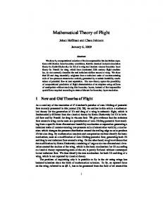
𝑘 = 2𝜋/𝜆 is the wave number, and 𝜆 is the wavelength. The N-LUT method which is like a convolution [18–21] can be applied only to the third element of (15) and the property of mathematical symmetry of the image; in this way the multiplicative computational complexity is reduced. For example, a binary image (black and white) would make zero multiplications and (𝑘 − 1)𝑁2 sums, where 𝑘 is the number of pixels other than zero. For the case of sparse and binary images, where 𝑘 is a small number, the multiplicative complexity is kept at zero while the additive complexity decreases a lot. To clarify the results above, let us consider the following example. For a hologram of one row 1 × 5 and one image of the same size, the distances from each image point to each hologram point depict a symmetry distance vector (d5, d4, d3, d2, d1, d2, d3, d4) as shown in Figure 1; each distance or its approximation obtained by using the MaClaurin polynomial is used in the core of the Fresnel integral. Once the distances from the first point have been calculated, these can be used to calculate the distances of other points of the hologram, so it is no longer necessary to make redundant calculations of distances. This can be extended to two dimensions as shown from Figure 2 through Figure 5. Figure 2 shows the distance matrix from an image of 3 × 3 to the first point of the hologram. Similarly, Figure 3 shows the distance matrix can be obtained for all points of the hologram.
4
Mathematical Problems in Engineering Image
Image d1
d2
d4
d3
d3
d5
d2
d1
d2
d3
Hologram
Hologram (c)
(a)
Image Image d2
d1
d3
d2
d4
d3
d2
d1
d2
d4 Hologram Hologram (d) (b) Image d5
d4
d3
d2
d1
Hologram (e)
Figure 1: Redundant distances generated by symmetry for the 5 hologram points ((a), (b), (c), (d), and (e)) with respect to the image points.
d1
d2
d3
d9
d8
d7
d8
d9
d6
d5
d4
d5
d6
d3
d2
d1
d2
d3
d6
d5
d4
d5
d6
d9
d8
d7
d8
d9
d4
d5
d6
d7
d8
d9
Figure 2: Distance matrix of a 3 × 3 image.
Figure 3: Distance matrix for all points of the hologram.
Figure 4 shows how Figure 3 is obtained. The matrix of Figure 4(b) is obtained by reflecting to the left the last two columns of the matrix of Figure 4(a). The matrix of Figure 4(c) is obtained by reflecting the last two rows of the matrix of Figure 4(b) upwards. The hologram can be obtained from Figure 4(c). To obtain the first point of the hologram, a 3×3 submatrix is used; in this first case, a 3×3 submatrix located in the lower right corner in Figure 4(c) is considered. The dimensions of this submatrix are the same as the dimensions of the original image. For the next point of the hologram, it is considered again a 3 × 3 submatrix but this time shifted one column to the left. This procedure is repeated until the row is completed (see Figure 5). Each submatrix is applied to the image as a dot product between matrices so that all points of this row of the hologram are calculated. To obtain the second row of the hologram, we use the 3 × 3 submatrix shown in the lower left corner of Figure 5; the
same process is repeated as in the first row, and so on, until the whole hologram is generated. Using this property of mathematical symmetry of the distances and image, the multiplicative computational complexity is reduced in the creation of digital holograms.
3. Results Given a two-dimensional image, the hologram is created using the algorithm described in this work. It is worth mentioning that the algorithm does not improve the quality of the holograms of Fresnel using the N-LUT method and the peak signal-to-noise ratio (PSNR), and the structural similarity (SSIM) index is the same. This is because the methods of Raytracing, LUT, N-LUT, and the proposed method use the same equations to calculate the hologram. The difference is only the computational complexity of the algorithm.
Mathematical Problems in Engineering
d1
d2
d4
d5
d7
d8
5 d9
d8
d7
d8
d9
d6
d5
d4
d5
d6
d3
d2
d1
d2
d3
d3
d2
d1
d2
d3
d6
d6
d5
d4
d5
d6
d6
d5
d4
d5
d6
d9
d9
d8
d7
d8
d9
d9
d8
d7
d8
d9
d3
(a)
(b)
(c)
Figure 4: The sequence of (a), (b), and (c) shows how to obtain a distances symmetric matrix with respect to 𝑑1 in (c).
d9
d8
d7
d8
d9
d9
d8
d7
d8
d9
d9
d8
d7
d8
d9
d6
d5
d4
d5
d6
d6
d5
d4
d5
d6
d6
d5
d4
d5
d6
d3
d2
d1
d2
d3
d3
d2
d1
d2
d3
d3
d2
d1
d2
d3
d6
d5
d4
d5
d6
d6
d5
d4
d5
d6
d6
d5
d4
d5
d6
d9
d8
d7
d8
d9
d9
d8
d7
d8
d9
d9
d8
d7
d8
d9
Hologram
Hologram
h1
h2
h3
h4
h5
h6
h7
h8
h9
Hologram
h1
h2
h3
h4
h5
h6
h7
h8
h9
Hologram
h1
h2
h3
h4
h5
h6
h7
h8
h9
d9
d8
d7
d8
d9
d9
d8
d7
d8
d9
d6
d5
d4
d5
d6
d6
d5
d4
d5
d6
d3
d2
d1
d2
d3
d3
d2
d1
d2
d3
d6
d5
d4
d5
d6
d6
d5
d4
d5
d6
d9
d8
d7
d8
d9
d9
d8
d7
d8
d9
···
h1
h2
h3
h1
h2
h3
h4
h5
h6
h4
h5
h6
h7
h8
h9
h7
h8
h9
Hologram
Figure 5: Each point of the hologram is computed by performing the dot product between the image and the distance matrix. In this example, the size of both, the hologram and the image, is 3 × 3 pixels.
Table 1: Comparison of computation time and memory size for each method. For a grayscale image.
Computation time for 1 point (ms) Total memory size for LUT (megabytes)
N-LUT
Proposed algorithm
0.0170
0.00993
0.0625
0.0625
Let us now analyze the computational complexity through the image of Figure 6(a) and its binary form of Figure 6(d). The hologram and reconstruction are shown in Figures 6(b) and 6(c) and Figures 6(e) and 6(f), respectively.
Table 2: Comparison of computation time and memory size for each method. For a binary image and sparse.
Computation time for 1 point (ms) Total memory size for LUT (megabytes)
N-LUT
Proposed algorithm
0.00207
0.00207
0.0625
0.0625
The algorithm was programmed in Matlab and data from [22] was used. The time used to obtain each point of the hologram as well as the amount of memory required is shown in Table 1. Table 2 shows the computational complexity of the N-LUT
6
Mathematical Problems in Engineering
(a) Original image bitmap of 128 × 128 (2794 no black pixels)
(b) Hologram of (a)
(c) Reconstruction of (b)
(d) Original binary image bitmap of 128 × 128 (678 no black pixels)
(e) Hologram of (d)
(f) Reconstruction of (e)
Figure 6: Different holograms and their reconstructions with 𝜆 = 632 nm and 𝑧 = 0.516 (proposed algorithm). The image has a size of 128 × 128 pixels.
Table 3: Computational complexity for a grayscale image. N-LUT
Proposed algorithm
Multiplicative computational complexity
𝑁4
255 ∗ 𝑁2
Additive computational complexity
𝑁4
𝑁4
Table 4: Computational complexity for a binary image.
Multiplicative computational complexity
N-LUT
Proposed
0
0
Additive computational complexity, where 𝑝 is the number of pixels 𝑁2 (𝑝 − 1) other than zero.
𝑁2 (𝑝 − 1)
Our algorithm applied on two colors images has a positive impact on multiplicative computational complexity, which is reduced from 255𝑁2 to 0. It is relevant to mention that the algorithm for binary and sparse images has a very low or zero multiplicative computational complexity and it is independent of image size; however, the additive complexity has not been significantly reduced. The computational complexity for a grayscale image is reduced approximately to the half with respect to N-LUT algorithm.
Conflicts of Interest The authors declare that there are no conflicts of interest regarding the publication of this paper.
Acknowledgments method and our method for obtaining the digital hologram of a grayscale image. The computational complexity of both methods for a digital hologram of a binary image is shown in Table 3. Note in Table 4 that the computational complexity for a binary and sparse image is much lower than for a grayscale image.
4. Conclusions The use of group theory and image symmetry properties allow the reduction of the computational complexity in the creation of digital holograms.
The authors gratefully acknowledge the PRODEP (UNACAR) and the CONACyT FOMIX (CIMAT Yucatan 2014) for their support.
References [1] U. Schnars, Digital Holography, Springer, New York, NY, USA, 2005. [2] Y. Ichihashi, H. Nakayama, T. Ito et al., “HORN-6 specialpurpose clustered computing system for electroholography,” Optics Express, vol. 17, no. 16, pp. 13895–13903, 2009. [3] M. Lucente, “Interactive computation of holograms using a look-up table,” Journal of Electronic Imaging, vol. 2, no. 1, pp. 28–34, 1993.
Mathematical Problems in Engineering [4] J. Jia, Y. Wang, J. Liu et al., “Reducing the memory usage for effective computer-generated hologram calculation using compressed look-up table in full-color holographic display,” Applied Optics, vol. 52, no. 7, pp. 1404–1412, 2013. [5] T. Nishitsuji, T. Shimobaba, T. Kakue, and T. Ito, “Fast calculation of computer-generated hologram using run-length encoding based recurrence relation,” Optics Express, vol. 23, no. 8, pp. 9852–9857, 2015. [6] S. Jiao, Z. Zhuang, and W. Zou, “Fast computer generated hologram calculation with a mini look-up table incorporated with radial symmetric interpolation,” Optics Express, vol. 25, no. 1, pp. 112–123, 2017. [7] D.-W. Kwon, S.-C. Kim, and E.-S. Kim, “Efficient digital hologram generation using reflection symmetry of principle fringe pattern,” in Proceedings of the ICTC 2010, pp. 197-198, IEE, Jeju, South Korea, November 2010. [8] S. Lee, H. C. Wey, D. K. Nam, D. S. Park, and C. Y. Kim, “Fast hologram pattern generation by radial symmetric interpolation,” in Optics and Photonics for Information Processing VI, Proceedings of SPIE, pp. 84980O-1–84980O-7, San Diego, Calif, USA, August 2012. [9] S.-C. Kim and E.-S. Kim, “Effective generation of digital holograms of three-dimensional objects using a novel look-up table method,” Applied Optics, vol. 47, no. 19, pp. D55–D62, 2008. [10] S. Cho, B.-K. Ju, N.-Y. Kim, and M.-C. Park, “One-eighth lookup table method for effectively generating computer-generated hologram patterns,” Optical Engineering, vol. 53, no. 5, Article ID 054108, 2014. [11] N. Okada, T. Shimobaba, Y. Ichihashi et al., “Fast calculation of a computer-generated hologram for RGB and depth images using a Wavefront recording plane method,” Photonics Letters of Poland, vol. 6, no. 3, pp. 90–92, 2014. [12] H. Wei, G. Gong, and N. Li, “Improved look-up table method of computer-generated holograms,” Applied Optics, vol. 55, no. 32, pp. 9255–9264, 2016. [13] Ye. A. Shelomov, “On m correlation matrices,” II journal communications Technology and electronics, vol. 39, no. 13, pp. 79– 91, 1994. [14] E. Shelomov, J. Seguel, A. Ortiz, J. Ruz, and G. Shelomova, “An´alisis de Fourier en grupos finitos con utilidades de Matlab,” in Proceedings of the CINVESTAV, 2002, pp. 90–116, CINVESTAV, Mexico City, Mexico, june 2002. [15] M. Hamermesh, Group Theory and Its Applications to Physical Problems, Addison-Wesley, New York, NY, USA, 1962. [16] D. K. Maslen and D. N. Rockmore, “The cooley–tukey FFT and group theory. Modern signal processing,” MSRI Publications, vol. 46, 2003. [17] R. Johnsonbaugh, Discrete Mathematics, Prentice Halls, New York, NY, USA, 6th edition, 2005. [18] Poon T.-C. and P. P. Banerjee, Contemporary Optical Image Processing with MATLAB, Rastogi and Inaudi, Oxford, UK, 1st edition, 2001. [19] T. C. Poon, Optical Scanning Holography with MATLAB, Springer Science and Business Media, Berlin, Germany, 2007. [20] J. W. Goodman, Introduction to Fourier Optics, Roberts and Company Publishers, 2005. [21] R. P. Muffoletto, Numerical techniques for Fresnel diffraction in computational holography [Ph.D. thesis], University of Louisiana, 2006. [22] T. F. Ra´ul, Modulaci´on completa del plano complejo mediante pantallas de cristal l´ıquido. Aplicaci´on a la reconstrucci´on de
7 hologramas de Fresnel digitales [Ph.D. thesis], University of Barcelona, 2004.
Advances in
Operations Research Hindawi Publishing Corporation http://www.hindawi.com