Ninth International Water Technology Conference, IWTC9 2005, Sharm El-Sheikh, Egypt 593
APPLICATION OF MAX-MIN ANT SYSTEM FOR JOINT LAYOUT AND SIZE OPTIMIZATION OF PIPE NETWORKS M. H. Afshar Assistant Professor, Department of Civil Engineering, Iran University of Science and Technology, P. O. Box 16765-163, Narmak, Tehran, Iran 16844 E-mail:
[email protected]
ABSTRACT The application of Max-Min Ant System for layout and size optimization of pipe networks is described in this paper. The formulation conventionally used for pipe size optimization of networks with fixed layout is extended to account for layout and pipe size determination of the networks. This is achieved by including a new constraints regarding the reliability of the network and modifying the availability constraints of the optimization problem. An engineering concept of reliability is used in which the number of independent paths from source nodes to each of the demand nodes is considered as a measure of reliability. The method is capable of designing the layout and pipe sizes of the water distribution networks of predefined reliability including tree-like and looped networks. It is also shown that a layout optimization of network followed by size optimization does not lead to an optimal or a near-optimal solution. The performance of the method for layout and pipe size optimization of pipe networks is tested against two benchmark examples in the literature and the results are presented. KEYWORDS: Ant algorithm; Tree and looped networks; Layout and size optimization
INTRODUCTION Optimization of water distribution networks is a multidisciplinary task involving hydraulics, quality, reliability, and availability of components requirements. In spite of all the progress made, the optimization of pipe networks fulfilling all these requirements seem to be out of reach at the present time. Most of the current investigations are, therefore, restricted to considering the hydraulics and availability requirements, leading to the so-called optimal pipe sizing of the pipe networks. The reliability requirement is usually addressed by considering a predefined fixed, usually looped, layout for the networks to be designed (Murphy et al. [15]; Dandy et al. [5]; Halhal et al. [10]; Savic and Walters [17]; Cunha and Sousa [4]; Boulos et al. [2]; Wu and Simpson [21]; Maier et al. [12]; Zecchin et al. [22]). All these investigations neglect the influence of the layout on the pipe sizing of the pipe networks.
594 Ninth International Water Technology Conference, IWTC9 2005, Sharm El-Sheikh, Egypt
Some researchers, on the other hand, have addressed the layout geometry optimization of the pipe networks, neglecting the influence of the pipe sizing on layout determination. Most of the works in this area focused on branched networks, which are of little use in water distribution networks due to poor reliability (Walters and Lohbeck [19]; Davidson and Goulter [7]; Walters and Smith [20]; Geem et al. [9]). Some researchers, however, considered the more difficult problem of looped networks (Davidson [6]). The joint problem of layout and pipe size design of branched water distribution networks has not attracted any attention mostly because they lack reliability. Failure or scheduled maintenance of any of the pipes would lead to a part of the network being cut off from the source nodes. The problem of layout and pipe size optimization for looped water distribution networks, however, is addressed by a few researches mostly because of its complexity (Rowel and Barnes [16]; Morgan and Goulter [13]; Morgan and Goulter [14]; Kessler et al. [11]; Cembrowicz [3]). In this paper, Max-Min Ant System (Stutzle and Hoos [18]) is used for joint layout and pipe-size optimization of pipe networks with a given level of reliability. In the following, the problem of least-cost layout and pipe size design is first formulated. The MMAS algorithm is then introduced and the problem of layout and pipe size optimization of water distribution networks is then formulated. The necessity of a coupled solution of the layout and pipe sizing problem is shown by comparing the results produced by the proposed method with that of a decoupled two-level approach on a benchmark problem. Finally, the applicability of the model for the optimization of real world pipe networks with predefined reliability is illustrated using a second benchmark example in the literature.
FORMULATION OF JOINT LAYOUT AND SIZE OPTIMIZATION OF PIPE NETWORKS The optimal design of a pipe network with a pre-specified layout in its standard form can be described as: Min.. Co =
N i =1
Ci Li
(1)
in which N is the number of existing pipes; Li and C i are length and per unit cost of the ith pipe, respectively, and Co represents the total cost of the pipes in the network. Subject to: 1. Hydraulic Constraints: i∈in( k )
i∈P
qi −
Ji = 0
qi = Qk
i∈out ( k )
k = 1,...., J
(2)
l = 1,...., L
(3)
Ninth International Water Technology Conference, IWTC9 2005, Sharm El-Sheikh, Egypt 595
J i = µL(
qi β −γ ) d chi
(4)
where J and L is the number of existing nodes and loops in the network, respectively; qi is the flow rate in pipe i; Qk is the required demand at consumption node k; Ji is the head loss in the ith pipe; chi is the Hazen-Williams coefficient for the ith pipe, and: = 1.85, = −4.87, µ = 10.5088 for q in cubic meter per hour and d in inch (Savic and Walters [17]; Boulos et al. [2]). 2. Nodal head and Pipe Flow Velocity Constraints: H min ≤ H k ≤ H max Vmin ≤ Vi ≤ Vmax
(5) (6)
k = 1,...., J
i = 1,..., N
in which H k is the nodal head; H min and H max are minimum and maximum allowable nodal head; Vi is the pipe flow velocity; and Vmin and Vmax are minimum and maximum allowable flow velocity. 3. Pipe size availability constraints: i = 1,..., N (7) di ∈ d in which d i is the diameter of pipe i; and d denotes the set of commercially available pipe diameters.
A penalty method is often used to formulate the optimal design of a pipe network as an unconstrained optimization problem in which head and flow constraints are included in the objective function, leading to a new problem defined by the minimization of the following penalized objective function subject to the constraints defined in Eq. (7). N
N
N
J
J
i=1
i=1
i=1
k=1
k=1
Cp = CiLi +αp{ (Vi /Vmin −1)2 + (Vi /Vmax−1)2 + (Hk / Hmin −1)2 + (Hk / Hmax−1)2}
(8)
where p is the penalty parameter with large value when the constraints are violated, and zero value otherwise. Here, the cost of the most expensive network is used as the penalty parameter. The hydraulic constraints are satisfied via the use of a simulation program that explicitly solves the set of hydraulic constraints for nodal heads (Afshar [1]). This formulation can be easily extended to the problem of joint layout and pipe size optimization. The reliability constraint in pipe network optimization problems is usually enforced by assuming a looped layout for the network and defining a minimum size for the available pipe diameters (Eq. 7). It is well-known that relaxing this constraint in the absence of any reliability requirement would lead to a branched network as the optimal solution of the problem. The resulting branched network is in
596 Ninth International Water Technology Conference, IWTC9 2005, Sharm El-Sheikh, Egypt fact the same initial looped network in which the diameters of the redundant pipes are set to zero. Adding a zero pipe diameter to the list of available pipe diameters would, therefore, enable the optimization algorithm to remove, if required, pipes from the network in its search towards an optimal layout. It is, therefore, sufficient to add a proper reliability constraint to the previous set of constraints and include a zero option in the set of commercially pipe diameters to arrive at the formulation of the least-cost layout and pipe size optimization problem. The reliability constraint can be defined as:
Rk ≥ R
(9)
in which Rk is the reliability of the demand node k of the trial network and R is the required level of reliability of the optimal network. The reliability of a demand node is the number of independent paths from the source nodes to the demand node. Including these constraints into the penalized objective function of Eq. 8 leads to the final form of the objective function. Minimize Cj = Cp + Cr with C r = C max
J
(10)
( R − Rk )2 if R < R and Cr = 0 otherwise, where Cmax is the cost of
k =1
most expensive network. The same procedures and algorithms currently used for optimal pipe sizing can then be used for the underlying problem. The procedure requires a predefined maximum layout, including all the possible and useful links which could contribute to the optimum layout of the network. This layout should include all candidate links within the network. The complete set of all candidate links can be theoretically very large, but the physical conditions, such as street right of ways, private easements, topography, etc., generally restrict the actual number of candidate links to a considerably smaller subset. It is obvious that the maximum layout for every network should be determined by the user and provided as a part of the input for the model.
MAX-MIN ANT SYSTEM Ant algorithm developed by Dorigo et al. [8], is a discrete combinatorial optimization algorithm based on the collective behavior of ants in their search for food. Over a period of time, a colony of ants is able to find the shortest route from their nest to a food source. The swarm intelligence of the ant colony is achieved via an indirect form of communication that involves the ants depositing and following a chemical substance, called pheromone, on the paths that they travel. Over time, shorter and, therefore, more desirable paths are reinforced with greater amounts of pheromone, as they require less time to be traversed, thus becoming the dominant path for the colony. To apply ant algorithm to a combinatorial optimization problem, it is required that the underlying problem is represented as a graph. For this, consider a graph consisting of n
Ninth International Water Technology Conference, IWTC9 2005, Sharm El-Sheikh, Egypt 597
decision points ( dpi ; i = 1,2 ,..., n ) where each decision point is connected to its adjacent decision point via a set of edges. For example, l ij ; j=1,2,…NEi represents the set of edges available at decision point i where NEi represents the number of available edges at the decision point i. A solution termed a path is then comprised of a selection of an edge at each decision point. An ant generates a solution by selecting an edge at each decision point based upon a probabilistic decision policy. The decision policy used in the original ant algorithm (Dorigo et al[8]) is as follows:
pij ( k ,t ) =
[ τ ij ( t )] α [ η ij ] β NEi j∈1
[ τ ij ( t )] α [ η ij ] β
(11)
where p ij ( k , t ) is the probability that ant k selects edge l ij while at decision point i at iteration t; τ ij ( t ) is the concentration of pheromone on edge l ij at iteration t; ij is a heuristic value representing the desirability of selecting edge l ij ; and α and β are two parameters that control the relative weight of the pheromone trail and heuristic value referred to as pheromone and heuristic sensitivity parameter. At the end of an iteration where all ants have generated a solution, the pheromone on each edge is updated. A modified form of the original pheromone updating rule suggested by Dorigo et al. [8] is used here as follows: τ ij ( t + 1 ) = ρτ ij ( t ) + ( 1 − ρ )∆τ ij
(12)
where τ ij (t + 1) is the amount of pheromone trail on edge l ij at iteration t+1; τ ij ( t ) is the concentration of pheromone on arc l ij at iteration t; 0 ≤ ρ ≤ 1 is the coefficient representing the pheromone persistence factor sometimes referred to as pheromone evaporation factor; and ∆τ ij is the change in pheromone concentration associated with arc l ij . Different methods are suggested for calculating the pheromone change. In a method suggested by Dorigo et al. [8], all ants deposit pheromone on the edges they have selected to produce the solution, ∆τ ij =
m k =1
∆τ ijk
(13)
in which ∆τ ijk is the pheromone deposited by ant k on arc l ij during iteration t. In another method suggested by Stutzle and Hoos [18] and used here, only the ant which has produced the best tour is allowed to contribute to pheromone change,
598 Ninth International Water Technology Conference, IWTC9 2005, Sharm El-Sheikh, Egypt *
∆τ ij = ∆τ ijk (14) * in which k is the cycle number which resulted in the best tour during iteration t.
The amount of pheromone change is defined as (Dorigo et al. [8]): ∆τ
k ij
R = f(Sk ) 0
if arc l ij is chosen by ant k
(15)
otherwise
where f ( S k ) is the cost of the solution produced by ant k and R is a quantity related to the pheromone trail called pheromone reward factor. Ants deposit an amount of pheromone proportional to the quality of the solutions they produce. Consequently, arcs that form part of lower-cost solutions receive more pheromone and are more likely to be chosen in future iterations. This choice helps to direct search towards good solutions. When an elitist strategy is used for pheromone updating, early stagnation of the search may occur. In this situation the trail strength on one of the options available at each decision point is so high compared to other options that nearly always the same option is chosen by the ants. No better solutions are, therefore, found by the ants and usually the best found solution is constructed by most of the ants. Stutzle and Hoos [18] introduced MMAS to have a more direct control over the influence of the pheromone strength. They introduced two limiters for the pheromone trail to prevent early stagnation of the search at a suboptimal solution. These limiters act as the upper and lower bounds of the pheromone trail strength. Stutzle and Hoos [18] introduced the following relations for the calculation of the upper and lower trail strength limit based on some analytical arguments: τ max ( t + 1 ) =
τ min ( t + 1 ) =
R f(S
gbest
( t ))
τ max ( t + 1 ).( 1 − p dec )
p dec = ( p best )1 / n
NE avg . p dec
(16) (17) (18)
where τ max ( t + 1 ) and τ min ( t + 1 ) represents the upper and lower limit for the pheromone trail strength, respectively; p dec is the probability that an ant constructs each component of the global-best solution again and p best is the probability that the current global-best solution is constructed again, given that all non-global best edges have a pheromone level of τ min ( t + 1 ) and all global-best edges have a pheromone strength of τ max ( t + 1 ) ; n is the number of decision points; and NEavg is the average number of edges at each decision point.
Ninth International Water Technology Conference, IWTC9 2005, Sharm El-Sheikh, Egypt 599
4
6
3
5
3
4
2 1 1 2 Fig. 1(a). Base graph of the typical problem. d 1,nsize . . d 1,1 d 1,0
dp 1
d 2 ,nsize
d 3 ,nsize
d 4 ,nsize
d 5 ,nsize
d 6 ,nsize
. . d 2 ,1
. . d 3 ,1
.
. .
d 4 ,1
. . d 5 ,1
d 2 ,0
d 3 ,0
d 4 ,0
d 5 ,0
d 6 ,0
dp 5
dp 6
dp 2
dp 3
.
dp 4
d 6 ,1
Fig. 1(b). Graph representation of the joint layout and size optimization problem.
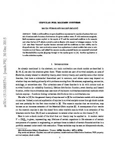
PROBLEM FORMULATION The problem of joint layout and pipe size optimization is considered to be a difficult problem compared to two-level layout and size optimization mainly due to the large search space involved. The size of the search space rapidly expands with increasing network size and the number of available pipe sizes. The total number of possible tree networks for a base graph of 12 link and 13 possible pipe sizes is 212 + 813 = 5.5 x 10¹¹ in a two-level layout and size optimization while it increases to 1214 = 2.26 x 10¹⁵ for a joint layout and size optimization. Application of ant algorithm to the problem of joint layout and pipe size optimization requires that the problem is recast in a proper form. For this, each link of the base graph is considered as the decision points of the problem. The number of decision points is, therefore, equal to the number of links in the base graph. The available options or edges at each decision points would, therefore, be the available pipe sizes for the link including a null option, where the null option corresponds to the 'no link' option. In this formulation, a typical joint layout and pipe size optimization problem shown in Fig. 1(a) can be represented by the graph shown in Fig. 1(b), where d i1 ,d i 2 ,...., d i ,nsize represents the list of available sizes for pipe i and nsize is the number of commercially available pipe diameters assumed here to be the same for all links and d i 0 = 0 represents the 'no link' option. In this formulation, as seen from Fig. 1(b), the available options at each decision point are independent from the decisions made at previous decision point and, therefore, the decisions can be made independently. The order in which the decisions are made is immaterial in this representation of the optimization problem.
600 Ninth International Water Technology Conference, IWTC9 2005, Sharm El-Sheikh, Egypt The local heuristic η ij representing the desirability of available options is taken equal to the inverse of the cost of the option to be chosen. Direct implementation of this definition for local heuristics, however, runs into difficulty as the value of local heuristics for the 'no pipe' option would be equal to infinity leading to the selection of the 'no pipe' option at all the decision points. This problem is overcome here by assuming that the desirability of the 'no pipe' option for each link is equal to half of the desirability of the option with the lowest allowable pipe size of the same link.
MODEL APPLICATION The first example to be considered is that of a simple network shown if Fig. 2. The network consists of nine nodes, twelve links, and a source located at node number 9. This example has been considered as a test network by Geem et al. (2002) to test the performance of the model they proposed for layout geometry optimization in the absence of size optimization. The water demand at each node of the network is shown in Table 1. The pipes are considered to be of 100 meter long. The pipe cost in one link is assumed to be proportional to its length and the flow along the link Cost = Length (Flow)1/2. The total number of total combinations is 212 = 4,096 and the number of possible trees is 192. The top four solutions of least cost can be obtained (Geem et al. [9]) by complete enumeration as shown in Fig. 3. These data are augmented here by additional data so that the network can be used as an appropriate test example for the joint layout and size optimization algorithm proposed. This would also make it possible to compare the results of layout geometry optimization with that of joint layout and size optimization. Table 2 shows the data regarding available pipe sizes and their cost. The Hazen-Williams coefficient is assumed equal to 130 for all the pipes. The elevation of all the demand nodes is set equal to zero and that of the source node is assumed to be 50 m. Minimum pressure requirement of 30 meter is only used at all the demand nodes. Table 3 shows the results of size optimization performed on the four top layouts obtained from enumeration using the data of Table 2. Partial enumeration and proposed ant algorithm were used to obtain these solutions to make sure of the optimality or near optimality of the results. The results shown in Table 3 can, therefore, be considered as the four top solutions which can be obtained by decoupling the layout and size optimization for the underlying example. It is surprisingly seen that the top solution of the layout optimization process yields the second most expensive network upon size optimization. The optimal solution is obtained with the second top solution of the layout optimization process. These results clearly show that layout geometry optimization in the absence of optimal sizing would not lead to the optimum network regarding both layout and pipe sizes. This is further supported by comparing these solutions with the solution obtained with the proposed joint layout and pipe size optimization procedure shown in Table 4 (the corresponding network to this solution is illustrated in Fig. 4). This Table shows the optimal layout and pipe diameters along with the corresponding nodal pressures obtained using the following values for the MMAS parameters: m = 100, = 0.85, = 1, = 0.2, and pdec = 0.10. It is seen that
Ninth International Water Technology Conference, IWTC9 2005, Sharm El-Sheikh, Egypt 601
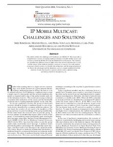
that the solution of simultaneous layout and size optimization problem with a cost of 39,800 is about 3% cheaper than the solution obtained in a two-level layout and size optimization process. In fact, this solution has the same cost but different layout as the solution resulting from pipe size determination of the second top solution of the layout optimization. These observations clearly show that joint layout and size optimization is unavoidable in a search towards optimal or near optimal design of pipe networks. The best solution of 39,800 is obtained within 7,900 function evaluations. This can be compared with the about 9,200 and 250,000 network analysis required by one of the most recent (Boulos et al. [2]) and earliest (Savic and Walters [17]) genetic algorithms for pipe size optimization of a network with 8 pipes and 13 available diameters, a problem with a much smaller search space compared to the problem considered here. The second example is considered to demonstrate the applicability and efficiency of the method for the layout and pipe size design of real-world networks. The network, shown in Fig. 5, is the small part of the Winnipeg system with 2 sources, 20 nodes, and 37 possible links. The available pipe diameters and their costs are shown in Table 5 while the length of the 37 possible links included in the maximum layout of the network along with the nodal demands and minimum nodal head requirements are shown in Table 6. The problem is solved for two different levels of reliability, namely level 1 and level 2, where the reliability of level n refers to the minimum number of independent paths from source nodes to each and every demand node. Figure 6(a) and Table 7 show the resulting layout, pipe diameters, and nodal heads for reliability level 1 obtained using the following values for the MMAS parameters: m = 100, = 0.95, = 1, = 0.25, and pdec = 0.10. It should be remarked that the method was able to find the optimal branched solution of 1,710,121$ within 22800 network evaluations. It is also seen from Figure 6(a) that the resulting solution is composed of two separate branched network since the network has two reservoirs. The optimal layout and the corresponding pipe sizes and nodal pressures with reliability level two is shown in Figure 6(b) and Table 8, respectively. The optimal looped solution of 2,055,917$ was obtained within 31500 network evaluations with the following values for MMAS parameters: m = 100, = 0.95, = 1, = 0.2, and pdec = 0.10.
602 Ninth International Water Technology Conference, IWTC9 2005, Sharm El-Sheikh, Egypt 10
6
12
8
9
9
6 3
5
5
11 7
8 4
2 1
1
2
7 4
3
Figure 2. Maximum (Base) Layout of the Test Network 1. 6
10
12
8 9
3
5
1
1
5
10
1
1
12
8
9
1
2
3
7
4
9
9 5
3
11 7
4
4
3
12
8
6
11
5
10
6
7 1
2
II
9
3
7 7
4
2
6
8
7
I 6
9 11
3
7 4
12
8
6
11
5
10
6
9
1
1
2
7 4
IV III Figure 3. Top Four Layouts Obtained from Enumeration for Network 1. 6
10
12
8
9
6 3 2 1
11 5
8
7
4 2
7 4
Figure 4. Optimal Layout Obtained for Network 1 with Reliability Level 1.
Ninth International Water Technology Conference, IWTC9 2005, Sharm El-Sheikh, Egypt 603
Table 1. Nodal Demand for Network 1. Node Demand (l/s)
1 2 3 4 5 5 7 8 9 10 20 10 20 10 20 10 20 -120
Table 2. Cost Data for Network 1. Diameter (cm) Cost (units/m)
1 2 3 4 6 8 10 12 14 16 18 20 22 2 5 8 11 16 23 32 50 60 90 130 170 300
Table 3. Optimal Pipe Size Solutions Obtained for Four Top Layouts of Network 1. Link
Diameter (cm) Node Pressure (m) (I) (II) (III) (IV) (I) (II) (III) (IV) 1 10 10 10 12 1 31.63 30.90 32.66 30.29 2 2 33.54 32.81 34.56 31.08 3 14 14 3 30.71 31.06 31.89 30.82 4 14 14 4 37.12 35.64 37.39 32.60 5 8 5 36.37 37.26 34.14 33.91 6 8 10 10 6 36.77 36.72 33.80 32.73 7 10 14 14 12 7 44.00 42.92 44.68 35.43 8 8 8 43.65 42.72 39.80 38.73 9 14 8 14 9 ------------10 10 12 12 12 11 12 16 16 10 12 18 14 14 16 Cost($) 41,900 39,800 40,700 42,400 Table 4. Optimal Layout and Pipe Size Solutions for Network 1 (Reliability Level 1). Link Diameter(cm) Node Pressure(m) 1 10 1 31.26 3 14 2 33.17 5 10 3 31.01 7 16 4 36.00 9 10 5 32.92 10 10 6 32.92 11 14 7 39.80 12 14 8 39.80 Cost($) 39,800 9 ---Table 5. Cost per Meter for Different Pipe Diameters of Network 2. Diameter (mm) Cost ($/m)
125 150 200 250 300 350 400 450 500 550 600 650 700 58 62 71.7 88.9 112.3 138.7 169 207 248 297 347 405 470
604 Ninth International Water Technology Conference, IWTC9 2005, Sharm El-Sheikh, Egypt
Figure 5. Maximum (Base) Layout of Network 2.
a) Reliability Level 1
b) Reliability Level 2
Figure 6. Optimal Layout Obtained for Network 2 with Reliability Level 1 and 2.
Ninth International Water Technology Conference, IWTC9 2005, Sharm El-Sheikh, Egypt 605
Table 6. Details of Network 2. From To Length Node Demand Min. Head Link (m) (l/s) (m) 1 1 2 760.00 1 165 75.00 2 1 4 520.00 2 220 74.00 3 1 6 890.00 3 145 73.00 4 2 3 1120.00 4 165 72.00 5 2 5 610.00 5 … 102.00 6 2 6 680.00 6 140 73.00 7 3 5 680.00 7 175 67.00 8 3 7 870.00 8 180 72.00 9 4 8 860.00 9 140 70.00 10 4 9 980.00 10 160 69.00 11 5 7 890.00 11 170 71.00 12 5 10 750.00 12 160 70.00 13 6 9 620.00 13 190 64.00 14 6 10 800.00 14 200 73.00 15 7 12 730.00 15 150 73.00 16 7 13 680.00 16 … 96.00 17 8 9 480.00 17 165 67.00 18 8 15 860.00 18 140 70.00 19 9 11 800.00 19 185 70.00 20 9 14 770.00 20 165 67.00 21 10 11 350.00 22 10 12 620.00 23 11 12 670.00 24 11 16 790.00 25 11 18 1150.00 26 12 13 750.00 27 12 17 550.00 28 13 17 700.00 29 14 15 500.00 30 14 16 450.00 31 14 19 750.00 32 15 19 720.00 33 16 18 540.00 34 16 19 700.00 35 17 18 850.00 36 18 20 750.00 37 19 20 970.00
606 Ninth International Water Technology Conference, IWTC9 2005, Sharm El-Sheikh, Egypt
Table 7. Optimal Layout and Pipe Sizes for Network 2 (Reliability Level 1). Diameter Node Pressure Link (mm) (m) 1 400 1 38.68 2 300 2 50.67 5 550 3 37.85 6 250 4 33.23 7 250 5 11 350 6 31.85 12 400 7 35.28 16 350 8 30.87 18 350 9 38.62 20 300 10 40.45 21 300 11 32.44 22 350 12 34.96 29 400 13 31.51 30 500 14 44.86 33 400 15 37.63 34 300 16 35 300 17 30.15 36 300 18 40.97 19 41.93 Cost ($) 1,710,121 20 31.78
Table 8. Optimal Layout and Pipe Sizes for Network 2 (Reliability Level 2). Pressure Diameter Node (m) Link (mm) 1 400 1 33.49 2 350 2 45.32 5 450 3 35.97 7 250 4 32.61 8 125 5 9 125 6 30.41 11 350 7 39.23 12 350 8 33.08 13 200 9 36.87 14 200 10 48.86 16 300 11 36.85 18 350 12 31.89 20 300 13 30.57 23 400 14 47.38 24 400 15 40.04 26 150 16 27 250 17 30.01 29 400 18 38.26 30 550 19 36.67 33 350 20 33.37 34 300 35 250 36 200 37 300 Cost ($) 2,055,917
CONCLUDING REMARKS The application of the MMAS to simultaneous layout and size optimization of pipe networks with a given reliability was described in this paper. An engineering concept of reliability was used in which the number of independent paths from the source node to the demand nodes was taken as a measure of the reliability. The formulation of the pipe network optimization with fixed layout was extended by relaxing the availability constraint of the problem and including a reliability constraint to be used for joint layout and pipe size optimization. Each link of the base graph was considered as the decision point of the problem in this formulation. The applicability and efficiency of the proposed methods for layout and size optimization of networks was tested against two benchmark examples in the literature and the results were presented. The first example was used to show the necessity of the superiority of the joint layout and size optimization to that of a two-level method while the second example was intended to
Ninth International Water Technology Conference, IWTC9 2005, Sharm El-Sheikh, Egypt 607
illustrate the capability of the proposed method for simultaneous layout and size optimization of real world network with a given reliability.
REFERENCES 1. Afshar, M. H., An Element-by-Element Algorithm for the Analysis of Pipe Networks. Int. J. for Eng. Science, 12(3), 87-100, 2001. 2. Boulos, P. F., Wu, Z. Y., Orr, C. H., and Ro, J. J., Least-cost design and rehabilitation of water distribution systems using genetic algorithms. Proceedings of the AWWA IMTech Conference, April 16-19, Seattle, WA., 2000. 3. Cembrowciz, R. G.,Water supply systems optimisation for developing countries, Pipeline Systems, B. Coulbeck and E. Evans, eds., Kluwer Academic, London, 59-76, 1992.
4. Cunha, M., and Sousa, J., Water distribution network design optimisation: simulated annealing approach, J. Wat. Resour. Plng. and Mgmt., ASCE, 125(4), 215-221, 1999. 5. Dandy, G. C., Simpson, A. R., and Murphy, L. J., An improved genetic algorithm for pipe network optimization, Wat. Resour. Res. 32(2), 449-458, 1996. 6. Davidson, J. W., Evolution program for layout geometry of rectilinear looped networks., J. of Computing in Civil Engineering, ASCE, 13(4), 246-253, 1999. 7. Davidson, J. W., and Goulter, I. C., Evolution program for design of rectilinear branched networks, J. of Computing in Civil Engineering, ASCE 9(2), 1-10, 1995. 8. Dorigo, M., Manielzo, V., and Colomi, A., The ant system: optimization by a colony of cooperating ants. IEEE Transactions Systems. Man and Cybernetics 26 29-42, 1996. 9. Geem, Z. W., Kim, J. H. and Yoon, Y. N., Optimal layout of pipe networks using harmony search, 4th. Int. Conf. on Hydro-Science and Engineering, Seoul, South Korea, 2000. 10. Halhal, D., Walters, G.A., Quazar, D., and Savic, D.A., Water network rehabilitation with structured messy genetic algorithm, J. Wat. Resour. Plng. and Mgmt, ASCE 123(3), 137-146, 1997. 11. Kessler, A., Ormsbee, L., and Shamir, U., A methodology for least-cost design of invounarable water distribution networks, Civil Engrg. Sys., 1, 20-28, 1990. 12. Maier H.R., Simpson, A.R., Zecchin, A.C., Foong, W.K., Phang, K.Y., Seah, H.Y. and Tan, C.L., Ant colony Optimization for design of water Distribution Systems, J. Water Resour. Plan. Management, ASCE, 129(3), 200-209, 2003. 13. Morgan, D.R., and I. C. Goulter, Least cost layout and design of looped water distribution systems, in Proc. of Ninth Int. Symp. on Urban Hydrology, Hydraulics and Sediment Control, University of Kentucky, Lexington, KY, July 27-30, 1982. 14. Morgan, D.R., and I. C. Goulter, Optimal Urban Water Distribution Design, J. Water Resour. Res., ASCE, 21(5), 642-652, 1985. 15. Murphy, L. J., Simpson, A. R., and Dandy, G. C., Design of a network using genetic algorithms, Water 20, 40-42, 1993. 16. Rowel, W. F., and Barnes, J. W., Obtaining layout of water distribution systems, J. Hydraul. Div., ASCE, 108(1), 137-148, 1982.
608 Ninth International Water Technology Conference, IWTC9 2005, Sharm El-Sheikh, Egypt 17. Savic, D. A. and Walters, G. A., Genetic algorithms for least-cost design of water distribution networks, J. Wat. Resour. Plng. and Mgmt, ASCE 123(2), 67-77, 1997. 18. Stutzle, T., Hoos, H.H., MAX-MIN ant system, Future Generation Computer Systems 16, 889-914, 2000. 19. Walters, G. A., and Lohbeck, T. K., Optimal layout of tree networks using genetic algorithms, Engrg. Optimization, 22, 27-48, 1993. 20. Walters, G. A., and Smith, D. K., Evolutionary design algorithm for optimal layout of tree networks, Engrg. Optimization, 24, 261-268, 1995. 21. Wu, Z. Y., and Simpson, A. R., A self-adaptive boundary search genetic algorithm and its application to water distribution systems, J. of Hydraulic Res. 40(2), 191203, 2002. 22. Zecchin, A.C., Maier, H.R, Simpson, A.R., Roberts, A., Berrisford, M.J. and Leonard, M., Max-min ant system applied to water distribution system optimization, Modsim 2003 - International Congress on Modelling and Simulation, Modelling and Simulation Society of Australia and New Zealand Inc, Townsville, Australia, 14-17 July, Vol. 2, pp.795-800, 2003.