vessels. This led to the development of the Polar Code, which came into force in 2017. Fatigue failure of a structural component is the combination of two stages ...
Fifth International Symposium on Marine Propulsors smp’17, Espoo, Finland, June 2017
Application of Polar Class Rules for Fatigue to an Existing Arctic Class Icebreaker Propeller Md Asif Amin1, Brian Veitch1 1
Faculty of Engineering and Applied Science, Ocean and Naval Architecture Engineering, Memorial University of Newfoundland (MUN), St. John’s, NL, Canada
ABSTRACT
This paper presents a benchmark evaluation of an existing propeller design in accordance with the requirements in the current ABS rules for Polar Class vessels. The propeller is from the existing Canadian R-Class icebreaker, which was originally designed and built to the Canadian Arctic Class construction standard. The Canadian Arctic Class rules required very highly strengthened vessels. The hull structural aspects of the Polar rules have been well explored in relation to existing high ice class requirements; the present work explores the machinery requirements. The propeller is found to meet the Polar Class 6 (PC6) requirements, based on fatigue assessment. The blade strength assessment is found to meet the requirements of PC1. KEYWORDS
Polar Class rules, R-Class propeller, Blade force, Fatigue strength. 1 INTRODUCTION
Early ice class rules were relatively crude and typically were simple percentage increases over open water requirements. Today through the IMO (International Maritime Organization) and IACS (International Association of Classification Societies), high ice class requirements are being standardized in the form of the Polar Class rules. These rules represent the latest guidance available for ice going vessels, so they have a relatively short history. In the 1970s and 1980s, there was an increase in activities in Polar waters. In response, several administrations took initiatives to establish a framework for detailed ice-class requirements for the construction and operation of vessels. This led to the development of the Polar Code, which came into force in 2017. Fatigue failure of a structural component is the combination of two stages of failure: crack initiation and
crack propagation. Fatigue life is the combined loading cycles over the two stages causing the structure to fail. In analyzing fatigue strength of a propeller, both dynamic loading and fatigue strength properties of the material must be considered. Most of the failures regarding marine propeller blades are reported as the consequence of the initiation of a fatigue crack at the blade root. Tokuda et al. (1978) and Helle (1981) reported that the fatigue life of marine propellers can be calculated based on the fatigue crack initiation period and crack propagation rate to cause failure. Wenschot et al. (1983) investigated the corrosion fatigue strength of a marine propeller of Ni-Al-Bronze and established a relationship between the tensile strength and the corrosion fatigue properties of the alloy. Bose et al. (1998) investigated the design analysis approach of propeller blades under different limit states and proposed two additional limit states for considering ice loading for ice class propellers, besides elastic limit state and fatigue limit state. Bose et al. (1998) also suggested designers perform detailed stress analysis using suitable finite element methods to get an accurate picture of stress distribution in blades under ice loading. Some investigations have been done in recent years regarding the fatigue damage of ice class vessels, but mostly limited to the ship hull. Suyuthi et al. (2013) developed a systematic procedure for assessing fatigue damage of ship hulls navigating in ice covered waters. Liu et al. (2015) performed design and optimization analysis of an existing R-Class marine propeller, based on IACS (International Association of Classification Society) URI3 rules using a panel method code. Although Liu et al. (2015) included direct stress and bending moments in the analysis, no calculation was performed to assess the fatigue strength of propeller. The present investigation demonstrates the fatigue assessment of the same R-Class marine propeller blade considered by Liu, applying ABS Polar Class machinery rules.
2 APPROXIMATE CORRESPONDENCE AMONG ICE CLASS RULES
Table 2. Description of different Polar Classes under IMO and IACS UR (Unified Requirements) are given below:
The development of new harmonized IACS Polar Class rules aimed to reduce the number of types of high ice class rules. For example, ABS removed their high ice class rules and replaced them with the Polar Class rules in 2012. The new machinery rules are the product of long term research and development efforts, which include full-scale trials, laboratory investigations, numerical simulations of propeller-ice interaction, and analysis of ice class propeller damage history.
Polar Class
Hice (m)
Sice
Description
PC1
4.00
1.2
Year-round operations in all polar waters
PC2
3.50
1.1
Year-round operations in moderate multi-year ice conditions
An approximate correspondence among ice-classes is shown in Table 1.
PC3
3.00
1.1
Year-round operations in second-year ice, which may include multi-year ice
PC4
2.50
1.1
Year-round operations in thick first-year ice, which may include old ice
PC5
2.00
1.1
Year-round operations in medium first-year ice, which may include old ice
PC6
1.75
1.0
Summer / autumn operations in medium first-year ice, which may include old ice
PC7
1.50
1.0
Summer / autumn operations in thin first-year ice, which may include old ice
Table 1. Approximate correspondence among ice-classes:
Higher Ice Class
Polar Class
CASPPR
PC1
CAC1
PC2
CAC2
PC3
CAC3
FSICR
PC4 CAC4 PC5 PC6
Type A
PC7 Type B
IAA IA IB IC
Table 2 is extracted from IACS Machinery Requirements for Polar Class Ships (IACS-UR-I3), 2006 Table 2 contains values of ice thicknesses specified by Polar Class rules (Hice) and ice strength index (Sice) for PC3 and other Polar Classes. These values are used for calculating propeller blade forces. 3 ASSESSMENT METHOD AND RESULTS
Lower Ice Class
Table 1 is prepared based on the information given in Ship Safety Bulletin (Bulletin no. 04/2009) of Transport Canada, CASPPR (Canadian Arctic Shipping Pollution Prevention Rule), and Maritime Safety Regulation (TraFi 31299/2010) of Transport Safety Agency, Finland. The R-Class propeller considered for the present fatigue study has been used by 3 similar CCGS (Canadian Coast Guard Ship) ice-breakers: Sir John Franklin (renamed as CCGS Amundsen), Pierre Radisson, and Des Groseilliers. These ice-breakers were designed and built to Canadian Arctic Class 3 (CAC3). With reference to the above table regarding the approximate correspondence among ice classes, it is noted that CAC3 approximately corresponds to PC3 (Polar Class 3). In the present study, the R-Class propeller is assessed by applying the criteria of ABS Polar Class rules for all 7 Polar Classes.
ABS Polar Class rules for machinery are applied here to determine and apply the blade forces, in order to check the blade strength. The R-Class propellers are open, so the rules for open propellers are used. After assessing the blade strength, the stress results are used to assess blade fatigue strength. As there is no guideline to perform fatigue strength assessment in IACS URI3 (2007), guidelines from ABS Steel Vessel rules are used to carry out the fatigue assessment. CAD software is used to do solid modeling of the propeller blade. FEA (Finite Element Analysis) software ANSYS Workbench is used to perform the simulation, meshing, and analysis of the propeller blade. 3.1 Blade Force Calculation
Basically there are two (2) types of force on a propeller blade when it encounters ice. The first is contact load due to the penetration of the propeller blade into ice. The other force originates from non-contact hydrodynamic loads due to the presence of ice in the water. The contact loads can be described as due to milling of an ice block by a propeller blade, and as due to impact when ice blocks hit the blade at the back or face side.
In ABS Polar Class machinery rules two (2) types of loads are considered: maximum backward blade force (Fb) and maximum forward blade force (Ff). As per ABS rules, maximum backward blade force ‘Fb’ can be calculated using the following: F F
kN = 27 S
kN = 23 S
nD
nD
.
.
.
.
H
D
(1) .!
D
(2)
Equation (1) is applicable when D < Dlimit_b and equation (2) is applicable when D ≥ Dlimit_b , where Dlimit_b = .! 0.85 H . For maximum forward blade force ‘Ff’: F% kN = 250 F% kN = 500 &
1
d D
1−
* Hice
D D
(3) (4)
Table 4. Calculated blade forces on the R-Class propeller:
Fb_LC1 (kN)
Fb_LC2 (kN)
Ff_LC3 (kN)
1
1896
948
750
375
1138
2
1738
869
750
375
1043
3
1675
837
750
375
1005
4
1298
649
750
375
779
5
949
475
750
375
570
6
716
358
750
375
450
7
577
288
750
375
450
PC
Ff_LC4 Fb,Ff_LC5 (kN) (kN)
The loads are applied as uniform pressure over a specified area, as per the guidelines provided in ABS Polar Class machinery rules (ABS Rules for Building and Classing Steel Vessels, 2016; Part-6, Chapter-1, Section-3 (6-13)/9.5).
Equation (3) is applicable when D < Dlimit_f and equation (4) is applicable when D ≥ Dlimit_f , where Dlimit_f = &
*H .
/ 0
.
In equations (1) to (4), D, EAR, Z, n and d are propeller diameter (m), expanded area ratio, number of blades, nominal rotational speed in rps, and propeller hub diameter (m), respectively. There are 5 loading scenarios and 7 Polar Classes in the ABS Polar machinery rules. Load cases are described explicitly in the ABS Polar rules and hence they are not reported here. In determining the loads to be applied under different cases, particulars of the propeller for the CCGS R-class icebreaker were obtained from Liu et al. (2015) and official website of CCGS. Table 3. Particulars of ice breaker(s) and R-Class propeller used in the calculation:
Draft Power (Max. Continuous Rating) Propeller diameter Rotational speed at MCR No. of Propellers No. of blades (Z) EAR Blade root thickness Hub diameter (d)
7.00 m 10,142 kW 4.115 m 3.0 rps 2 4 0.7085 280 mm 1.2806 m
Using equations (1) to (4), and particulars of the ice class propeller mentioned in Table 3, blade forces are calculated for the 7 Polar Classes (PC1 to PC7) and 5 Load Cases (LC1 to LC5) described in the Polar rules.
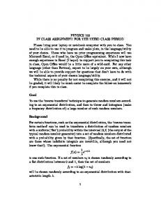
Figure 1: Variation of blade pressure for 5 load cases under 7 Polar Classes
As per the formula, Sice is not considered in calculating ‘Ff’. Propeller diameter (D) is less than Dlimit_f for all 7 Polar Classes and thus Hice is also not considered in calculating Ff. Thus equation (3) is used to calculate Ff, and there is no variation in loading with ice classes for load cases 3 and 4, as illustrated in Table 4 and Figure 1. Liu et al. (2015) assessed the strength of the same R-Class propeller. They concluded that the propeller blades were over-designed for PC3 (CAC3) and suggested optimization could save 1.4 tons of blade material. No fatigue assessment was performed by Liu et al. (2015).
3.2 Strength Assessment Criteria
In ABS Polar Class machinery rules at section 6-1-3/11.5, the criteria to assess maximum blade stress and blade fatigue design are described. In checking blade stresses (von Mises or equivalent), the criterion is: blade stresses obtained through applying backward or forward blade force shall not be greater than allowable stress for the blade material. Allowable stress, σall = σref / S, where S is the safety margin (usually 1.5) and σref is the reference stress. From the rules: σref = 0.7σu or 0.6σ0.2 + 0.4σu , whichever is less. σu is specified as the maximum ultimate tensile strength and σ0.2 is specified as maximum yield or 0.2% proof strength, if yield is not available. The R-class propeller blade is marine grade Ni-Al-Bronze (NAB) alloy, having σu = 620.5 MPa and σ0.2 = 268.9 MPa. Therefore σref = 410 MPa and σall = 273.3 MPa. So the maximum von Mises (or equivalent) stress pertaining to the blade under any load case and polar class shall not be greater than 273.3 MPa. The tensile strength and yield strength of the propeller blade material considered are the tested values for the R-Class propeller blade material, where minimum specified values are used, as per ABS rules. 3.3 Blade Stress Assessment: Modeling, Meshing and Simulation
A finite element analysis (FEA) technique or equivalent is required by the Polar Rules. One of the inputs to an FEA is a geometry that represents the propeller blade to be analyzed. For this work, a process was developed to produce a working 3D model using a simple table of offsets. The table of offsets was used to develop the geometry of 3D model of propeller blade incorporating pitch, skew and rake. From the geometry, a surface model and then a solid model of the propeller blade were generated to use for analysis in the FEA software. For the convenience of calculation, only 1 blade was analyzed and fillet at blade root was not modelled. As the NAB alloy used for the propeller blade is not available in the material library of the FEA software (ANSYS Workbench) used, the material was modeled using the properties of typical NAB material. Properties of material were obtained from Liu et al. (2015). Table 5. Properties of NAB material used in calculation:
Yield strength Ultimate tensile strength Proof stress Corrosion Fatigue strength (air) Corrosion Fatigue strength (salt water) Density
268.9 MPa 620.5 MPa 193.0 MPa 158.6 MPa 120.0 MPa 7556 Kg/m3
After modeling the 3D solid model of the propeller blade and material, the hub of the propeller was also modeled and integrated with the blade. Boundary constraints were applied at the internal surface of hub. Then meshing was performed using the meshing tool of FEA software.
Figure 2: diagrams showing unmeshed and meshed 3D models of propeller blade integrated with hub (fillet at the blade root was not modelled)
Analysis of the meshed model was done using the loads calculated according to the ABS rules. The stress results obtained through the analysis are shown in Table 6. Table 6. Stress (σ) results of the R-Class propeller blade:
σb_LC1 σb_LC2 σf_LC3 σf_LC4
σb, σf
(MPa)
(MPa)
(MPa)
(MPa)
_LC5 (MPa)
1
241
204
109
93
224
2
220
187
109
93
205
3
212
180
109
93
197
4
164
139
109
93
153
5
120
102
109
93
112
6
91
76
109
93
88
7
73
62
109
93
88
PC
3.4 Blade Fatigue Assessment
Fatigue is due to the cyclic loading acting on the structure over a period of time on a more or less regular basis. In the presence of cyclic loading, the structure may fail even at a stress below the allowable limit. Thus a fatigue assessment of the structure is important, even though the structure complies with the requirements of a stress assessment. The structure will fail when the cumulative load cycles becomes large enough to deteriorate the restoration capacity of structure. The duration over which such failure phenomenon occurs is called the fatigue life (Meese 2013 and Almar-Naess 1985). A fatigue assessment is typically based on an S-N curve, which shows the relation between stress intensity (∆σ) and the number of cycles before failure (N) encountered or likely to be encountered by the structure. For the case of propeller blades, fatigue is assessed based on the stresses as a result of the forward and backward bending forces.
Figure 3 is a graphical demonstration of mean stress (σm), stress intensity (∆σ), and stress amplitude (σa), which can be calculated as follows:
σm = (σhigh + σlow) / 2 σa = (σhigh - σlow) / 2 ∆σ = 2· σa σhigh σa Δσ σmean σσa a
σ= 0 σlow Figure 3: Showing fatigue stress terms
The stress values σhigh and σlow are derived from FEA simulation. These values represent the highest change of stress in an element in the analysis between compatible load cases.
different scenarios and they are shown in Table 7, ‘n’ is the shaft rotational speed in rps at MCR. In calculating Nice, it was assumed that the propeller center line was at a depth of 5.0 meter from the minimum ballast waterline in ice (LIWL) of the ship. The value of ‘Nice’ will vary with the variation of depth of submergence of propeller, as the value of ‘k2’ will also change accordingly: the higher the depth of submergence, the lower the number of load cycles encountered by the propeller blade (Nice). Next a Miner Summarize Table (MST) was developed in order to plot the limiting and actual S-N curve for blade material for all 7 Polar Classes. In developing the MST, the guidelines in ABS rules at 6-1-3/11.5.2 were followed. The loading frequency spectrum was divided into 10 blocks and each block incorporated 10% of the load. Table 8 was developed to show distribution of stress amplitude (σa) for all the Polar Classes. Similarly, Table 9 was also generated to give load cycles for each ice class and load block. The cumulative load cycles in Table 9 (last row of table), must be the same as Nice in Table 7. Table 8. Stress amplitude (σa) in MPa for all 7 Polar Classes:
Guidelines to do fatigue assessment for ice class propeller blade are not included in IACS URI3. ABS has included their requirements and guidelines for fatigue assessment in Polar rules (section 6-1-3/11). By following ABS rules, Table 7 was developed, illustrating stress intensity (∆σ), stress amplitude (σa), and cumulative number of load cycles (Nice) likely to be experienced by the R-Class propeller blade.
Loading
PC1
PC2
PC3
PC4
PC5
PC6
PC7
100%
212
199
194
163
135
116
105
90%
190
179
174
147
121
104
94
80%
169
159
155
131
108
93
84
70%
148
139
135
114
95
81
74
60%
127
119
116
98
81
70
63
Table 7: Stress (principal) intensity and cumulative load cycles (Nice) for the R-Class propeller
50%
106
99
97
81
68
58
53
40%
85
80
78
65
54
47
42
30%
63
59
58
49
41
35
32
20%
42
40
39
33
27
23
21
10%
21
20
19
16
13
12
11
∆σ (MPa)
(MPa)
1
424
2
PC
σa
Nclass
Nice
212
1.31 21.0E+6
165.56E+6
398
199
1.07 17.0E+6
109.24E+6
3
388
194
0.83 15.0E+6
74.52E+6
4
327
164
0.71 13.0E+6
55.69E+6
5
271
135
0.62 11.0E+6
40.72E+6
6
233
116
0.57
30.67E+6
7
210
105
k2
0.52
9.0E+6 6.0E+6
Table 9 was developed by calculating the number of load cycles under each block (ni). The formula used to determine the number of cycles in each block is: n = N
18.72E+6
In Table 7, ‘Nclass’ is the reference number of impacts per propeller rotation speed for each ice class, as given in ABS Polar rules (6-1-3/Table 6). ‘Nice’ was calculated based on Nclass using the formula given in ABS rules: Nice = k1 · k2 · Nclass · n
(5)
In equation (5), k1 = 2 for wing propeller, values for k2 were calculated using the formulas given in ABS rules for
1 . . 34 2
− 5n. 7
6
In equation (6), ‘i’ is the single load block (1 to 10), ‘z’ is the total number of load blocks (10), and ‘k’ is the Weibull exponent (typically 0.75 for open and 1.0 for ducted propeller). The complete MST for the R-class propeller blade is the combination of Table 8 and Table 9; due to space constraints they are shown separately. After developing the MST for all 7 Polar Classes, the S-N curves of the propeller of NAB were developed.
Table 9. Number of load cycles (ni) for all 7 Polar Classes:
PC1
PC2
PC3
PC4
PC5
PC6
PC7
100%
7
6
6
6
6
6
5
90%
37
34
31
29
27
26
23
80%
248
217
192
175
159
145
123
70%
1.65E+3
1.38E+3
1.18E+3
1.04E+3
915
812
659
60%
10.93E+3
8.81E+3
7.22E+3
6.21E+3
5.27E+3
4.55E+3
3.51E+3
50%
72.52E+3
56.08E+3
44.26E+3
36.95E+3
30.42E+3
25.51E+3
18.75E+3
40%
48.12E+4
35.70E+4
27.11E+4
21.98E+4
17.55E+4
14.30E+4
10.00E+4
30%
31.93E+5
22.72E+5
16.61E+5
13.08E+5
10.12E+5
80.18E+4
53.38E+4
20%
21.19E+6
14.46E+6
10.18E+6
77.85E+5
58.36E+5
44.95E+5
28.48E+5
10%
140.61E+6
92.08E+6
62.35E+6
46.33E+6
33.66E+6
25.20E+6
15.20E+6
Total
165.56E+6
109.24E+6
74.52E+6
55.69E+6
40.72E+6
30.67E+6
18.72E+6
Loading
In Table 9, the number of cycles under each block (ni) is calculated based on the formula provided in ABS rules, 61-3/11.1. As a prerequisite to apply the Miner Summarize method, the overall load spectrum must be divided into a minimum number of 10 load blocks, as described in ABS rules at 6-1-3/11.1.1. If a higher number of blocks is used, there will be a fewer cycles in each block, which will cause less fatigue damage to the structure and hence the cumulative fatigue damage of structure will be smaller. In that case, the calculation is less conservative. Similarly, if the number of blocks used is less than 10, the calculation is more conservative. The load distribution pattern follows the Weibull distribution, where cumulative distribution function of the probability distribution is an exponential function. S-N curves of the propeller blade are plotted in Figure 4 for the Ni-Al-Br (NAB) alloy. The limiting S-N curve (sloped straight line) for NAB material is plotted, as well as the S-N curves for all 7 Polar Classes. Guidelines described in ABS rules at section 6-1-3/11.5.2 were followed in generating the curves. The left hand side portion of S-N curve of the NAB material is a straight line having slope 4.5 and passing through the point (σE7, 107), where σE7 = {(σFAT-E7 / S) · Ksize · Kmean}. Here mean fatigue strength, σFAT-E7 = 120 MPa for Ni-Al-Bronze (CU3) alloy and safety factor, S = 1.5. ABS rules include formulas for geometric size factor, Ksize , and mean stress effect, Kmean , to calculate σE7. After plotting the first portion of limiting S-N curve up to 108 cycles, the second portion of the curve is plotted, which is also a sloped straight line starting at the end point of first portion of SN curve at 108 cycles and having a slope of 10. The effect of mean stress on the fatigue properties of blade material is taken into account by incorporating Kmean in the equation to determine fatigue limit stress (σE7). The σE7 formulation in the ABS Rules has a term σFAT-E7 , which is a Mean Fatigue Strength term based on R = -1 and a 50% survivability. The Kmean factor in the equation reduces σE7 as the change in stress moves away
from R = -1. Hence the limiting S-N curve will shift with the variation of mean stress, which will directly affect the fatigue properties of the blade material and the results of fatigue assessment. The ABS rules for Polar Class ships require the fatigue to be evaluated using a Miner’s Summation rule, described in ABS (Steel Vessels) Polar Class machinery rules at 61-3/11.1. As per the rule, the accumulated fatigue failure using linear elastic Miner’s rule must be less than 1.0. From the S-N curve (Figure 4) it is seen that for PC3 and above Polar Classes, fatigue failure or damage (Ɗ) is more than 1.0, as for these Polar Classes some portion of the actual S-N curves crosses the limiting S-N curve. Also for PC4, the S-N curve is overtaking the limiting S-N curve, and hence Ɗ for PC4 will also be more than 1.0. Thus ‘Ɗ’ was calculated only for PC5 and lower Polar Classes to assess the fatigue failure of the R-Class propeller blade using Miner’s Summation rule. Fatigue damages calculated are as follows: 7
1.0 Here ‘ni’ is the number of actual load cycles obtained from MST and ‘Ni’ is the allowable or limiting load cycles obtained by extending the S-N curve up to the limiting S-N curve. A similar calculation was done to check PC6. Thus for PC6 fatigue damage: Ɗ6 (PC6) = (0.0002 + 0.0009 + 0.003 + 0.009 + 0.022 + 0.052 + 0.099 + 0.172 + 0.111) = 0.469 < 1.0. With Ɗ6 < 1.0, the propeller design for the R-Class ice breaker meets the fatigue requirements of PC6. From the analysis it is noted that the fatigue damage of the R-Class propeller is proportionate to the cumulative number of load cycles (Nice) encountered by the propeller.
Figure 4: Showing limiting S-N curve (sloped straight lines) and actual S-N curves for PC6 and above Polar Classes 4 DISCUSSION ON RESULTS
The following conclusions and remarks can be made on the basis of the strength calculations and analysis done for the R-Class propeller blade: - Allowable von Mises stress determined in section 3.2 is 273.3 MPa and the maximum stress obtained for all 7 Polar Classes is 241 MPa (Table 6) for PC1. The maximum stress obtained for PC3 is almost 212 MPa. Hence the propeller blade design is adequate to meet the requirements of the highest Polar Class (PC1) based on blade stress assessment. - The R-Class propeller is found to meet PC6 (and lower Polar Classes) requirements based on the fatigue strength assessment, as the S-N curve for PC6 of the R-Class propeller design is below the limiting S-N curve and the Miner’s Sum (0.469) is less than 1.0. The S-N curve of RClass propeller for PC5 is also below the limiting S-N curve, but the Miner’s Sum (1.363) is more than 1.0 and thus the R-Class propeller design does not comply with the requirements for PC5. - The depth of the propeller center line of the vessel from LIWL (Minimum Ballast Water Line in Ice) is assumed 5.0 meter, which is more than the propeller diameter. The number of load cycles in the load spectrum per blade (Nice) will change considerably with the change of the depth of submergence of the propeller.
- Modeling of fillet radius at blade root was not done, which affects the results of the calculations due to the stress concentration. 5 CONCLUSIONS
This paper describes fatigue assessment based on ABS Polar Class rules for an existing ice-class propeller. The R-Class propeller was expected to meet PC3 or equivalent requirements, but based on the current fatigue assessment the propeller blade design meets PC6 conditions. 6 ACKNOWLEDGEMENT
The authors would like to acknowledge their gratitude to Mr. Dan Oldford, Senior Engineer, ABS (American Bureau of Shipping), HETC (Harsh Environment Technology Center) in Canada.
REFERENCES
ABS Rules for Building and Classing Steel Vessels (2016), machinery Requirements for Polar Class Vessels (Part 6, Chapter 1 and Section 3) Almar-Næss, A. (1985). ‘Fatigue Handbook - Offshore Steel Structures.’ Tapir. ISBN 82-519-0662-8. Bose, N., Veitch, B., Doucet, M. (1998). ‘A design approach for ice-class propellers.’ Transaction of Society of Naval Architect and Marine Engineers, 106. Helle, H. P. E. (1981). ‘An Investigation of Ship Propeller Fatigue.’ (Ph.D. Thesis). Deft University of Technology, Netherlands. IACS History Files (HF) and Technical Background (TB) documents for Unified Requirements (URs). (2014). IACS Machinery Requirements for Polar Class Ships (IACS-UR-I3), IACS Req. (2006) Rev.1, Corr. 1 (2007) Koskinen, P., Browne, R., Norhamo, L., Bakken, G. M. (2009). ‘Propeller Blade Design (Version-2)’. IACS Unified Requirements for Polar Ships, Technical Background Notes (IACS UR I3, TBN, draft). Liu, P., Bose, N., Veitch, B. (2015). ‘Evaluation, design and optimization for strength and integrity of polar class propellers.’ Journal of Cold Region Science and Technology, 113 (2015) 31-39 Meese, N. A. (2013). ‘Analysis of Ice-induced Vibrations and Comparison with Full-Scale Experimental Data.’ (MEng Thesis). NTNU, Norway. Suyuthi, A., Leira, B. J., Riska, K. (2013). ‘Fatigue damage of ship hulls due to local ice-induced stresses.’ Journal of Applied Ocean Research, 42 (2013) 87-104. Tokuda, S., Okuyama, Y., Inoue, H. (1978). ‘Fatigue Failure in Marine Propeller Blades.’ Propellers '78 Symposium, Virginia, May 24·25, 1978. The Society of Naval Architects and Marine Engineers, One World Trade Center, Suite 1369, New York. Transport Canada (2009). Bulletin no. 04/2009, ‘IACS Unified Requirements for Polar Class Ships, Application in Canadian Arctic Waters’. Ship Safety Bulletin, Canada. TraFi (Transport Safety Agency), (2010). ‘Finnish Ice Classes Equivalent to Class Notations of Recognized Classification Societies and Documentation Required for the Determination of the Ice Classes of Ships.’ Maritime Safety Regulation, Finland. Wenschot, P. (1983). ‘The Properties of Ni-Al Bronze Sand Cast Ship Propellers in Relation to Section Thickness.’ Naval Engineers Journal.