Application of Pseudo–cooling Boundary Conditions Combined With Electromagnetic and Thermal Weak Coupling for the Analysis of Highly Integrated Aerospace Actuators Themistoklis D. Kefalas
Antonios G. Kladas
School of Electrical and Computer Engineering National Technical University of Athens GR–15780, Athens, Greece
[email protected]
School of Electrical and Computer Engineering National Technical University of Athens GR–15780, Athens, Greece
[email protected]
Abstract—Two original numerical techniques are presented for the finite–element (FE) unsteady analysis of permanent magnet synchronous motors (PMSM) and induction motors (IM) operating in demanding aerospace applications. The first technique is the electromagnetic and thermal analysis weak coupling using a multi–slice FE model. The advantage of this technique is the representation of complex actuator geometries including skewed magnets, by using a low computational cost 2– D model while taking into consideration temperature dependent material attributes. The second technique deals with the application of pseudo–cooling boundary conditions for the emulation of the cooling housing of actuators. Those boundary conditions are applied at the outer areas of the actuators in contact with the housing and eliminate the need of modeling complex 3–D geometries of highly integrated actuator housings.
The second technique simplifies the modeling of highly integrated actuators by emulating complex housing configurations with properly defined thermal boundary conditions. The aforementioned techniques were incorporated into a FE package developed by the authors and used for the coupled electromagnetic and thermal analysis of PMSM and IM actuators, designed for demanding environmental conditions encountered in an aerospace application [4], [7]. II. ELECTROMAGNETIC AND THERMAL ANALYSIS WEAK COUPLING USING MULTI–SLICE FE TECHNIQUE
I. INTRODUCTION
The 3–D FE transient thermal simulation is coupled [17], with a multi–slice FE code for the evaluation of the heat sources. More specifically, the difference of the thermal and electromagnetic time constants has been exploited in order to ensure the updating of the copper conductivity and permanent magnet magnetization variation as the temperature increases.
Political economical, and environmental trends lead to the all electric aircraft concept and the corresponding elimination of high–pressure hydraulic lines [1]. Permanent magnet synchronous motor (PMSM) and induction motor (IM) actuators used in such contemporary aerospace applications, are highly integrated and function under harsh environmental conditions and large changes of loading conditions [2]–[8].
This is achieved by implementing a steady state two dimensional (2–D) FE electromagnetic analysis for several motor cross sections at every time–step of the unsteady heat transfer FE simulation. Furthermore, the temperature variation of the thermal conductivity, and the temperature dependent characteristics of materials and losses were taken into consideration [18], [19].
Keywords—aerospace industry; finite induction motors; permanent magnet motors;
element
methods;
The conventional approach for the numerical analysis of such devices, requires an elaborate coupled electromagnetic and thermal, three dimensional (3–D) finite–element (FE) transient analysis [9]–[12]. This paper proposes two original numerical techniques in order to reduce the complexity of the aforementioned problem. The first technique employs a multi–slice FE model, which in contrast with existing approaches appearing in the literature [13]–[16], is used for evaluating the heat sources of the 3–D thermal model.
The research leading to these results has received funding from the European Commission, in the frame of “Clean Sky” Programme, Topic Nbr: JTI–CS–2009–1–SGO–02–010 under grant agreement 255811EMAS.
III. THERMAL BOUNDARY CONDITIONS APPLICATION Due to the dense packaging of the aerospace actuator, the housing of the PMSM and IM has a multifaceted and irregular geometry with no 2–D or 3–D symmetry. In order to emulate this housing an original numerical method is developed [2]. The specific method consists in the application of appropriately defined boundary conditions at the outer area of the motors in thermal contact with the housing. The surface is partitioned into m facets each representing a different component of the actual housing e.g., a fin, or the area between two fins. At each facet a different boundary condition
TABLE I.
CHARACTERISTICS OF THE OPTIMIZED MOTORS
Design Parameter
PMSM
Number of phases Number of poles Number of stator slots Magnet angle (degrees) Number of rotor slots Motor active length (mm) Rotor outer radius (mm) Gap width (mm) Stator outer radius (mm)
IM
3 28 24 8.1 – 40 16.8 1.0 45
3 8 24 – 30 120 25.4 1.0 45 ''
is applied so that (1) is satisfied, where qi is the heat flux
(a)
(b)
i –th facet, hi is the convection coefficient of the i –th facet, and Tsi is the mean surface temperature of the i –th facet. transfer per unit area of the
m
m
∑q = ∑h ⋅T '' i
i =1
i =1
i
si
(1)
q is the heat transfer rate i.e., the sum of the actuators heat sources, and A is the sum of the m facets.
(c)
The left term of (1) must satisfy (2), where
m
∑ qi'' = q / A
(2)
i =1
IV. DESCRIPTION OF THE FE PACKAGE FOR ELECTROMAGNETIC AND THERMAL TRANSIENT ANALYSIS The numerical techniques of Sections II, III were integrated into a FE code written by the authors. The specific FE package consists of six codes and a control code. The control procedure calls the rest six codes and passes variables to them. For the storage of the FE matrices a modified Morse technique was used. The solution of the FE linear system is carried out by combining the specific assembly scheme and the conjugate gradient method with Van der Vorst preconditioning [3]. A considerable reduction in mesh size of the actuators FE models was achieved by considering the winding wire, the winding insulation, and the iron laminated cores as homogeneous and anisotropic domains at the finite elements level [20]. Finally, a procedure for generating time– steps was introduced in the FE transient solver. It is based on (3), where ∆t i is the i –th time–step of the unsteady analysis and a is equal to the first time–step
∆t1 .
∆t i = a ⋅ exp[b ⋅ (i − 1)], i = 1, 2...n
(3)
Fig. 1. Prototype actuators. (a) Stator of the PMSM and IM actuators. (b) Permanent magnet rotor. (c) Assembled TENV actuator.
The dimensionless parameter b satisfies (4) where T is the time period of the unsteady analysis and n is the number of time–steps of the unsteady analysis [3]. The aforementioned procedure is introduced in order to improve the resolution of the unsteady analysis during the first time–steps and to reduce the computational cost. n
T = ∑ a ⋅ exp[b ⋅ (i − 1)]
(4)
i =0
V. PROTOTYPE ACTUATORS AND SMCO PM DEMAGNETIZATION CHARACTERISTICS A. Prototype PMSM and IM Actuators A surface mounted PMSM and an IM were designed and optimized for a variety of operating conditions met in a demanding aerospace application [7], [8]. Under normal conditions of operation the torque and rotating speed are equal to 1.2 N ⋅ m and 180 rpm respectively. Under severe conditions of operation, torque and rotating speed are equal to 6.0 N ⋅ m and 6,000 rpm. A alternate–teeth–wound, non–overlapping, fractional slot concentrated winding and a conventional winding configuration were used respectively for the PMSM and IM. High temperature, samarium cobalt (SmCo) permanent
(a)
(b)
Fig. 2. (a) Setup for SmCo PM demagnetization characteristics evaluation. (b) Cross section of the magnetic circuit.
(a)
(b)
(c)
(d)
Fig. 4. Magnetic flux of the IM for different slipping frequencies and loading conditions. (a) s ⋅ f = 3 Hz and 1.2 N ⋅ m . (b) s ⋅ f = 15 Hz and 1.2 N ⋅ m . (a)
(c) s ⋅ f = 3 Hz and 6.0 N ⋅ m . (d) s ⋅ f = 15 Hz and 6 N ⋅ m .
variable air–gap and SmCo PM specimens. Fig. 2 shows the specific setup and the magnetic circuit. The motors under consideration are totally enclosed non– ventilated (TENV). Natural convection mechanism dominates and consequently air–turbulent movement in the air–gap is negligible. VI. RESULTS AND DISCUSSION
(b) Fig. 3. Flux density distribution of PMSM. (a) Normal mode of operation. (b) Extreme mode of operation.
magnets (PM) were used for the PMSM. For the rotor bars of the IM the NEMA design class A was adopted. Table I shows the design parameters of the optimized PMSM and IM, and Fig. 1 shows the prototype actuators [7]. B. Demagnetization Characteristics of SmCo PM SmCo PM demagnetization characteristics for different ambient temperatures were obtained experimentally [21]. A thermal chamber, incorporating a PID controller and a piezoelectric transducer, was used in order to determine the magnetic force of a simple magnetic circuit employing a
A. Multi–slice FE Electromagnetic Analysis Magnetostatic 2–D FE analyses are employed in every time–step of the 3–D FE unsteady heat transfer analysis in order to determine the heat sources of the PMSM and IM FE models i.e., the winding losses and the iron losses. The temperature dependent demagnetization characteristics of the SmCo PM of the PMSM were taken into consideration by using a set of demagnetization curves for various ambient temperatures and an appropriate interpolation scheme. Fig. 3 shows the flux density distribution of the PMSM for the normal and extreme mode of operation. Fig. 4 shows the magnetic flux distribution of the IM for two different slip frequencies s ⋅ f , and for the normal and extreme mode of operation encountered in the aerospace application under consideration. B. 3–D FE Transient Thermal Analysis A number of unsteady and steady state 3–D FE heat transfer analyses for various material attributes and load
Temperature (Co) (a)
(b) (a)
Temperature (Co)
Temperature (Co)
Fig. 5. 3–D FE of the actuators. (a) Detail of the FE mesh of the IM. (b) Cross–section of the FE mesh of the PMSM.
(a)
(b) Fig. 7. IM temperature distribution. (a) 82.7 s. (b) 2,607 s.
Temperature (Co)
all steps of the transient analysis. Fig. 7 shows that in the case of the IM the critical temperature component are the copper bars of the rotor. The aforementioned is due to the high slip frequency and respectively high induced currents during the extreme mode of operation.
(b) Fig. 6. PMSM temperature distribution. (a) 82.7 s. (b) 2,607 s.
conditions of the IM and PMSM, were performed using the FE code of Section IV integrating the numerical methodologies of Sections II and III. Tetrahedral meshes ranging from 1.0 ⋅ 10 6 to 2.0 ⋅107 elements and a conventional PC were used for the analyses. Figs, 5a and 5b show respectively, the FE meshes of the IM and the cross–section of the FE mesh of the PMSM as well as the various areas comprising the 3–D model. Figs. 6, 7 depict the distribution of the temperature of the PMSM and IM under the extreme operating condition for two steps of the unsteady analysis. The simulation time is 8,233 s, the first and the last time–step produced by the time–step generator are equal to 0.18 s and 5,626 s respectively. Fig. 6 clearly shows that the copper material of the stator is the most temperature intensive component of the PMSM for
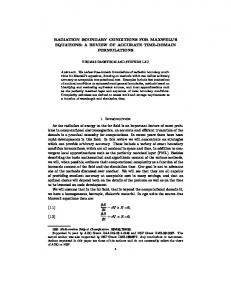
C. Application of Pseudo–cooling Boundary Conditions The technique of Section III is used for the emulation of an unsymmetrical housing of a PMSM actuator. Fig. 8 shows the respective motor, its housing, and a graphical representation of the pseudo–cooling boundary conditions technique. For the purpose of validation the authors carried out the same transient thermal analysis for the actual housing by applying a surface heat source, equal to the power losses of the PMSM, in its inner surface. Fig. 9 shows the distribution of the temperature for two time–steps of the unsteady thermal simulation, of the emulated PMSM housing and the actual housing. The two distributions agree within 0.5% to 3.5%. The shaft and the end–windings of the PMSM are not shown for clarity and the housing is rotated so that the reader can compare the two distributions. D. Experimental Validation of Numerical Techniques The numerical techniques proposed in this paper were compared by temperature measurements taken under rapid load tests of the PMSM. A data acquisition card, variable resistors, a torque meter, and type–k thermocouples were used for the temperature measurements [2].
140 120
Temperature (oC)
100 80 Housing Center Housing End Winding End
60 40 20 0 0
20
40
60 80 Time (min)
100
120
(a) 140
Fig. 8. Graphical representation of the pseudo–cooling technique in the case of a PMSM and its unsymmetrical housing.
120
Temperature (oC)
100 80 Housing Center Housing End Winding End
60 40 20 0 0
20
40
60 80 Time (min)
100
120
(b) (a)
Fig. 10. Temperature variation of the PMSM at three locations. (a) First set of measurements. (b) Second set of measurements.
For all measured points, the measured and simulated temperature distributions agree within 1% to 4%.
(b) Fig. 9. Comparison of temperature distribution of emulated PMSM housing and actual housing. (a) 8.21 s. (b) 8,233 s.
Fig. 10 shows the measured temperature versus time at three locations of the PMSM for two different load conditions.
The first set of thermal evaluation measurements, shown in Fig. 10a, was performed for a rotating speed of 750 rpm, stator current of 4.92 A, and line–to–neutral voltage of 49 V. The environmental temperature was constant at 25 oC, and the measurements were performed for a duration of 2 h using constant ohmic electrical loads. The second set of thermal evaluation experiment, shown in Fig. 10b, was performed for a rotating speed of 1,000 rpm, stator current of 6.45 A, and line–to–neutral voltage of 65 V. Again, environmental temperature was kept steady at 25 oC, and the measurements were performed for 105 min using constant electrical loads. The respective load used in this case was higher than the one used for the first set of measurements with the purpose of increasing further the equilibrium temperature of the permanent magnet motor.
VII. CONCLUSION The two numerical techniques proposed in this paper reduce the computational cost of the coupled electromagnetic thermal analysis by reducing the complexity and size of the 3– D FE models. The application of the pseudo–cooling boundary conditions permits the emulation of cooling housings of motors without actually modeling the complex 3–D geometry of the motor housing. Furthermore, proper mapping of the specific boundary conditions onto the surface of the motor in thermal contact with the housing enables the emulation of a number of housings of different configurations. On the other hand, the weak coupling of the thermal analysis with the presented 2–D magnetostatic FE model, simplifies and partitions the coupled analysis into models of reduced complexity. Finally, the multi–slices technique is adopted in order to take into consideration PMSMs with skewed magnets and IMs with skewed rotor bars using the aforementioned 2–D magnetostatic FE models.
[9]
[10]
[11]
[12]
[13]
[14]
[15]
REFERENCES [1]
[2]
[3] [4]
[5] [6]
[7]
[8]
W. Cao, B. C. Mecrow, G. J. Atkinson, J. W. Bennett, and D. J. Atkinson, “Overview of electric motor technologies used for more electric aircraft (MEA),” IEEE Trans. Ind. Electron., vol. 59, no 9, pp. 3523–3531, Sep. 2012. T. D. Kefalas and A. G. Kladas, “Thermal investigation of permanent– magnet synchronous motor for aerospace applications,” IEEE Trans. Ind. Electron., vol. 61, no 8, pp. 4404–4411, Aug. 2014. T. D. Kefalas and A. G. Kladas, “Finite element transient thermal analysis of PMSM for aerospace applications,” Proc. ICEM, 2012. E. M. Tsampouris, M. E. Beniakar, and A. G. Kladas, “Geometry optimization of PMSMs comparing full and fractional pitch winding configurations for aerospace actuation applications,” IEEE Trans. Magn., vol. 48, no. 2, pp. 943–946, Feb. 2012. T. D. Kefalas and A. G. Kladas, “Transient heat transfer analysis of housing and PMM using 3–D FE code,” Proc. ICEM, 2016. K. Dimolikas, T. D. Kefalas, P. Karaisas, Z. K. Papazacharopoulos, and A. G. Kladas, “Lumped–parameter network thermal analysis of permanent magnet synchronous motor,” Journal of Materials Science Forum, vol. 792, pp. 233–238, 2014. P. E. Kakosimos, E. M. Tsampouris, A. G. Kladas, and C. Gerada, “Aerospace actuator design: A comparative analysis of permanent magnet and induction motor configurations,” Proc. ICEM, 2012. T. D. Kefalas and A. G. Kladas, “3–D FEM and lumped–parameter network transient thermal analysis of induction and permanent magnet motors for aerospace applications,” Journal of Materials Science Forum, vol. 856, pp. 245–250, 2016.
[16]
[17]
[18]
[19]
[20]
[21]
M. van der Giet, C. Schlensok, B. Schmulling, and K. Hameyer, “Comparison of 2–D and 3–D coupled electromagnetic and structure– dynamic simulation of electrical machines,” IEEE Trans. Magn., vol. 44, no. 6, pp. 1594–1597, Dec. 2008. M. Schrittwieser, O. Biro, E. Farnleitner, and G. Kastner, “Analysis of temperature distribution in the stator of large synchronous machines considering heat conduction and heat convection,” IEEE Trans. Magn., vol. 51, no. 3, pp. 1714–1717, Dec. 2015. A. M. Oliveira, P. Kuo–Peng, N. Sadowski, F. Rüncos, R. Carlson, and P. Dular, “Finite–element analysis of a double–winding induction motor with a special rotor bars topology,” IEEE Trans. Magn., vol. 40, no. 2, pp. 770–773, Dec. 2004. Z. Yujiao, R. Jiangjun, H. Tao, Y. Xiaoping, Z. Houquan, and Y. Gao, “Calculation of temperature rise in air–cooled induction motors through 3–D coupled electromagnetic fluid–dynamical and thermal finite– element analysis,” IEEE Trans. Magn., vol. 48, no. 2, pp. 1047–1050, Dec. 2012. B. Weilharter, O. Biro, S. Rainer, A. Stermecki, “Computation of rotating force waves in skewed induction machines using multi–slice models,” IEEE Trans. Magn., vol. 47, no. 5, pp. 1046–1049, Dec. 2011. S. Niu, S. L. Ho, W. N. Fu, and G. Z. Jian, “Eddy current reduction in high–speed machines and eddy current loss analysis with multislice time–stepping finite–element method,” IEEE Trans. Magn., vol. 48, no. 2, pp. 1007–1010, Dec. 2012. G. D. Kalokiris, T. D. Kefalas, A. G. Kladas, and J. A. Tegopoulos, “Special air–gap element for 2–D FEM analysis of electrical machines accounting for rotor skew,” IEEE Trans. Magn., vol. 41, no. 5, pp. 2020–2023, May 2005. T. Kefalas, G. Kalokiris, A. Kladas, and J. Tegopoulos, “Design of skewed mounted permanent magnet synchronous generators based on 2D and 3D finite element techniques,” Journal of Materials Processing Technology, vol. 161, pp. 288–293, 2005. J. P. Bastos, M. F. R. R. Cabreira, N. Sadowski, S. R. Arruda, and S. L. Nau, “A thermal analysis of induction motors using a weak coupled modeling,” IEEE Trans. Magn., vol. 33, no. 2, pp. 1714–1717, Dec. 1997. S. Ruoho, J. Kolehmainen, J. Ikäheimo, and A. Arkkio, “Interdependence of demagnetization, loading, and temperature rise in a permanent–magnet synchronous motor,” IEEE Trans. Magn., vol. 46, no. 3, pp. 949–953, Mar. 2010. N. Zhao, Z. Q. Zhu, and W. Liu, “Rotor eddy current loss calculation and thermal analysis of permanent magnet motor and generator,” IEEE Trans. Magn., vol. 47, no. 10, pp. 4199–4202, Oct. 2011. L. Idoughi, X. Mininger, F. Bouillault, L. Bernard, E. Hoang, “Thermal model with winding homogenization and FIT discretization for stator slot,” IEEE Trans. Magn., vol. 47, no. 12, pp. 4822–4826, Dec. 2011. O. Winter, C. Kral, and E. Schmidt, “Augmented temperature degrading effect of rare earth magnets arranged in segmented halbach arrays,” IEEE Trans. Magn., vol. 48, no. 11, pp. 3335–3338, Dec. 2012.