simple, decentralized control law for multiple vehicle agents by using gyroscopic forces and braking forces. As far as we known, reactive multi-agent approach ...
2008 20th IEEE International Conference on Tools with Artificial Intelligence
Application of reactive multi-agent system to vehicle collision avoidance YANG Sibo, GECHTER Franck, KOUKAM Abderrafiaa University of Technology of Belfort-Montbeliard (UTBM) Systems and Transportation Laboratory (SET) 90000, Belfort, France {sibo.yang, franck.gechter, abderafiaa.koukam}@utbm.fr
the travelling path of the cars. Traditionally, it can be realized by the signal sensors, the image processing or millimeter wave [1]-[3].The avoidance control strategy of the vehicle is to find the strategy to control the vehicle moving (the speed or direction) for avoiding the obstacles. In order to control the vehicle, some people use wireless communication networks and GPS device [4]-[7], some ones use the fuzzy logic-based controller [8]-[10], and others use the “Kalman filtering process” [11]. Sudha Arora and A.K.Mittal [12] introduce us a new method by introducing the “Priority Based Conflict Resolution” strategy to deal with the confliction of the AGVS (Automated Guided Vehicle Systems). Charles-Antoine Brunet [13] and Dong Eui CHANG [14] introduce an alternative approach for collision avoidance by introducing firstly the multi-agent systems: the former gives a multi-agent architecture for a driver model for Autonomous Road Vehicles and the latter illustrates a simple, decentralized control law for multiple vehicle agents by using gyroscopic forces and braking forces. As far as we known, reactive multi-agent approach has never been used as itself to be a decision process that is able to deal with the obstacle avoidance problem of the vehicle. Olivier Simonin and Franck Gechter [15] give us the methodology to design the reactive multi-agent systems. The main interests of the use of multi-agent systems especially reactive systems are the following intrinsic properties: adaptability, flexibility and reliability [16]. In this paper, we propose a vehicle collision avoidance solution based on the physics inspired reactive multiagent system. It is able to deal with both the obstacle detection and vehicle avoidance control. The focus of other existing multi-agent models of collision avoidance commonly look on a vehicle as a single agent and then use different mathematical algorithms to acquire the control strategy of the collision avoidance. The difference of our model is the fact that we take into account a global
Abstract Vehicle collision avoidance is a promising safety approach to new transportation systems, with innovative capabilities, such as obstacle detection, vehicle collision avoidance control strategy and adaptability to different obstacles. This paper presents a Reactive Multi-agent solution to the vehicle collision avoidance control problem with a linear configuration. In our case, vehicle collision avoidance is designed as a reactive multi-agent system in which agents interact with other agents and the obstacles situated in the environment by using physics inspired behaviors. Collision avoidance stability emerges as a global result of the individual interact ed agents. Vehicle avoidance control strategy stems from calculating the trajectories of the vehicle based on the decision process of the reactive multi-agent system. Furthermore, the adaptation to different kind of obstacles is made by tuning model’s physical parameters. In order to assert the transition from abstract to concrete, simulations experiments have been implemented and simulations results are analyzed.
1. Introduction Vehicle Collision Avoidance is a promising safety approach to new transportation systems, with innovative capabilities. It can be defined as a system for preventing collisions between a vehicle and other objects (which usually be called obstacles). Its main goal, when applied to civil cars, is to avoid the vehicle collision and increase the safety of vehicles in car travel. It can be divided into the two sub-problems: (i) Obstacle detection on the travelling path; (ii) Avoidance control strategy of the vehicle. Obstacle detection is to detect the obstacles on
1082-3409/08 $25.00 © 2008 IEEE DOI 10.1109/ICTAI.2008.134
197
Authorized licensed use limited to: IEEE Xplore. Downloaded on April 1, 2009 at 09:46 from IEEE Xplore. Restrictions apply.
and dynamic point of view by introducing the reactive multi-agent system into a vehicle and finding the collision avoidance solution for the vehicle by global behavioral observation and calculating of the reactive agents. This paper is structured as follows. The first part describes the multi-agent model used for the vehicle collision avoidance and the obstacle detection process. Second, the interaction model based on the Newtonian physics is defined. Third, the organization of decision agents was illustrated. Then the avoidance control strategy of vehicle is detailed. Finally, the simulations experiments and results analysis are exposed. The paper finishes with a conclusion and gives a presentation of our future work.
sensors installed on the vehicle. It is the link between the real world perceived by vehicle sensors and the decision agent world which goal is to make decisions for the vehicle. The environment has both static and dynamic attributes. The static attribute of the environment is named as Topology, it represents the static view of the environment. It commonly includes the perception length, range or images that sensors could detect. In the model, parameter L represents the length that the sensors could detect, parameter A represents the range that the sensors could detect and parameter C represents the storage images of the sensors. We could acquire the total information of the environment by using the fusion approach [15] of above data from the different sensors on the vehicle; The dynamic attribute of the environment is named as Dynamics, it represents the topology of the environment on its dynamic. It includes two dynamical changes [15] of the obstacles in front of the vehicle: the emergence of obstacles and the disappearance of obstacles. These two dynamic changes are continuously detected by the sensors installed on the vehicle as a loop.
2. The Multi-agent Model The multi-agent model formalized in this paper for vehicle collision avoidance is composed of four basic components: Environment, Agents, Interactions and Organization of the decision agents. In the model, we transformed the vehicle and its real world into the environment that the agents will face with. In this environment, each reactive agent is characterized by a set of attributes such as the mass, position and the speed. Each agent is also assigned to a specific role that can be characterized as a set of interaction behaviors. In order to realize the obstacle avoidance scenario, two main agent roles are defined: the decision agent role and the obstacle agent role. When the vehicle moves, the obstacle that the vehicle faced with is detected by the sensors installed on the vehicle and then to be added as an obstacle agent into the environment. The interactions between the decision agents and the obstacle agents are based on the physics inspired model according to the decision agent’s perception range. The avoidance control strategy for the vehicle is finally stems from the observation of the decision agents’ organization and calculating the trajectories of the vehicle. The calculating of the trajectories of the vehicle is according to the decision process from the decision agents that interacted with other decision agents and the obstacle agents situated in the environment. Moreover, the parameters of the multi-agent model can be configured manually or empirically in order to adapt the different situations. We will illustrate them in the following parts in detail.
2.2 Agents In the environment, two reactive agent roles are defined. One agent role is named as decision agent, it represents the reactive agent in the environment which goal is to make decisions for the vehicle; the other agent role is named as obstacle agent, it represents the real obstacles emerged or disappeared in the environment that the vehicle need to avoid. Their definitions are to be realized the obstacle avoidance scenario of the vehicle according to the decision process from the decision agents that interacted with other decision agents and the obstacle agents. Each agent role is characterized by some attributes parameters in our model. 2.2.1 Decision Agent The decision agent role has the attributes parameters m, s, v, a, r, R, IE (seen in Table 1). 2.2.2 Obstacle Agent The obstacle agent role can be regarded as an agent without some attributes or with a few attributes value changed. It has the attributes parameters M, S, V, A, SI, OIE, Fix (seen in the Table 2). 2.2.3 Obstacle Detection The obstacle detection process for the vehicle is directly related with the sensors installed on the vehicle. The sensors installed on the vehicle will continuously detect the real world of the vehicle to find whether an
2.1 Environment The environment defined in the multi-agent model is the perception length, range or images detected by the
198
Authorized licensed use limited to: IEEE Xplore. Downloaded on April 1, 2009 at 09:46 from IEEE Xplore. Restrictions apply.
Agent Interaction (A - A Interaction) and Decision AgentObstacle Agent Interaction (A-O Interaction).
Table 1. Attributes of the Decision Agent Attributes m s v a r R IE
Description mass of a decision agent position of a decision agent speed of a decision agent acceleration of a decision agent Perception range of a decision agent to another (seen in Figure 1) Perception range of a decision agent to an obstacle agent (seen in Figure 1) the internal energy of a decision agent
3.1 A-A Interaction A repulsion force emerged between two Decision Agents as the result of the A-A Interaction. This repulsion force takes action when two decision agents are closed to less than the perception range (repulsion range) r of an agent (seen in Figure 2). In the interaction model, we use the following physical force equation (1) to represent this kind of interaction: Ai A j Ai A j F AiAj m i m j m 2 , ( d r ) (1) 3 3 d Ai A j
Table 2. Attributes of the Obstacle Agent Attributes M S V A SI OIE Fix
Description mass of an obstacle agent position of an obstacle agent speed of an obstacle agent acceleration of an obstacle agent size of an obstacle agent the internal energy of an obstacle agent the Boolean value to indicate obstacle agent is fixed or not
F AiAj represents the repulsion force vector between the decision agent Ai and Aj, α (alpha) is defined by the gravitational constant between two decision agents, mi, mj are the masses of the two decision agents Ai and Aj , they are commonly the same value because the agents distribution are homogeneous (with same attributes), d = Ai A j is the distance between the decision agent Ai and Aj, r is perception range(repulsion force range) to another decision agent Aj of the decision agent Ai .
Figure 1. Perception range of a Decision Agent obstacle emerged on the traveling path. When the sensors capture an obstacle, they will send the position, size, speed and other information of the obstacle to the reactive multi-agent system and therefore an obstacle agent will be added into the environment according to the position and the size of the real obstacle.
Figure 2. Repulsion forces between two Decision Agents
3.2 A-O Interaction
3. Interaction Model A repulsion force emerged between a Decision Agent and an Obstacle Agent as the result of the A-O Interaction when an obstacle agent is in the perception range R of a decision agent (seen in Figure 3). In the interaction model, we use the following physical force equation (2) to represent this kind of interaction:
We assumed that the interaction behaviors between the decision agents and between the decision agents and the obstacle agents are followed the Newton’s law of gravitation according to the decision agent’s perception range. We defined them both as the repulsion behaviors in order to accord with the obstacle avoidance scenario. Therefore, there are two kinds of repulsion interactions emerged in the environment: Decision Agent- Decision
F AiOk mi M k
Ai Ok AO mi M k i k 3 , ( D R ) (2) 3 D Ai Ok
199
Authorized licensed use limited to: IEEE Xplore. Downloaded on April 1, 2009 at 09:46 from IEEE Xplore. Restrictions apply.
F AiOk represents the repulsion force vector between
ai of a decision agent Ai with the following difference
the decision agent Ai and obstacle agent Ok ,β (beta) is defined by the gravitational constant between the decision Agent and the obstacle Agent, mi is the mass of the decision agent Ai and Mk is the mass of the obstacle agent Ok, it is proportional to the size of the obstacle agent Ok. D = Ai Ok is the distance between the
equation (4) according to the Newton’s law of motion:
mi a i FAiAj FAiOk F f i j
k
Ai A j
n
mi m j
d
j 1
3
q
mi M k k 1
AiOk V Ai D3
(4)
(i, j [1, n], k [1, q ]; , , [0,1]; d r ; D R )
decision agent Ai and the obstacle agent Ok, R is the perception range (repulsion force range) to an obstacle agent Ok of the decision agent Ai .
Here
F
AiAj
represents the vector sum of the
j
repulsion forces of the decision agent Ai and other decision agents,the F represents the vector sum of
Ai Ok
k
the repulsion forces of the decision agent Ai and the obstacle agents it perceived. The indicator α (alpha) and β (beta) are the two gravitational constants to these two interactions of the decision agent Ai , d= Ai A j and D = Ai Ok are respectively the distances between decision agent Ai -Aj and the distance between decision agent Ai and obstacle agent Ok. Because the decision agents are homogeneous (with the same attributes), and their masses are always the same value. Therefore, we can simplify the equation (4) to the following equation (5):
Figure 3. Repulsion forces between a Decision Agent and an Obstacle Agent
3.3 Interactions behaviors in the Environment
mai
F
Ai A j
j
Besides the above F AiAj and F AiOk interaction forces of the decision agent Ai in the environment, the Fluid
n
m 2
j 1
friction force F f i has also been added to the interaction forces of the decision agent Ai taking into account the dynamics and the real world. It is also used to avoid the perpetual movement of the decision agents. The parameter λ is the friction factor, the Fluid friction force vector of the decision agent Ai ) : fi
V
Ai
k 1
Ai O k V Ai D3
(5)
(3)
4. Organization of the Decision Agents
Therefore, there are three kinds of interaction forces among the decision agents and obstacle agents in our interaction Model:
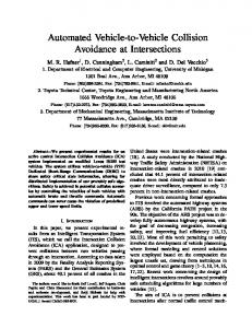
The result of the interaction behaviors between the decision agents and between the decision agents and the obstacle agents situated in the environment is that the decision agents will finally form a self organization to react to the obstacle agents in the environment (seen in Figure 4). In Figure 4, there are three fixed obstacle agents (three points in the center of the figure) in the environment and the decision agents (the most points surround the three points) form a self organization to
Agent-Agent Repulsion Force F AiAj Agent-Obstacle Repulsion Force F AiOk Fluid friction force F
3
q
m M k
( i , j [1, n ], k [1, q ]; , , [ 0 ,1]; d r ; D R ) By discrete integration to equation (5), we can calculate the new acceleration, velocity, position and energy of the decision agent Ai after interactions in the environment according to the Newton’s law of motion. Thus all the attributes parameters of agents defined in Table 1 and Table 2 could also be computed thanks to the equation (5).
F f i is as the following equation (3) ( V Ai is the speed F
k
Ai A j d
F Ai O k F f i
fi
By using above interaction forces defined in the multiagent model, we could calculate the acceleration value
200
Authorized licensed use limited to: IEEE Xplore. Downloaded on April 1, 2009 at 09:46 from IEEE Xplore. Restrictions apply.
react to the three fixed obstacle agents. The emerged short straight line in the south of the Figure 4 represents the mean position changes of the all the decision agents interacted in the environment as the time changed. Therefore, we can acquire the mean position change vector of the decision agents in each time step with the continuous observation of the decision agents’ organization and make it as the foundation of decision process to control the vehicle.
other decision agents and the obstacle agents situated in the environment. In this paper, we use the mean position vector of the decision agents that have interacted in the environment as the basic physical vector to calculate the trajectories of the vehicle, seen in equation (6).
S mean ( t )
1 n
n
S
Ai
( t ) (6)
i 1
Here the position vector S Ai (t ) is the position vector of the decision agent Ai (i=1..n) in time step t(t=1..m) in the environment, it can be easily calculated by the above equation (5). The position vector S mean (t ) is the current mean position of all the agents that have interacted in the environment in time step t. By calculating the position vector difference S mean (t ) between the current time t step
S mean (t ) (t=1…m) and the time t-1 step
S mean (t 1) , we can acquire the vehicle reference speed difference V mean (t ) by simplified discrete differential
Figure 4. The organization of the Decision Agents (three fixed obstacle agents)
to S mean (t ) . Therefore, we can see that the reference speed difference vector V mean (t ) is given by the decision agents interacted in the environment and inspired by the physics inspired interaction model. It is then used as a decision support vector which can automatically change the speed, direction and position of the vehicle. The automatic change of the vehicle speed and its position from the decision process of all the decision agents that interacted in the environment are shown in equation (7) and equation (8).
5. Avoidance Control Strategy to the vehicle The avoidance control strategy to the vehicle is shown in Figure 5. It is a continuous loop when the vehicle is moving.
Sensors
Multi-agent
Decision
Vehicle Speed (Fast/Slow)
Detection
System
Strategy
Orientation (Left/Right)
V ( t ) V ( t 1 ) V mean ( t ) (7) Here V (t 1) is the vehicle speed vector in time t-1 step, Vmean (t ) is the current reference speed difference
Figure 5. Reactive Multi-agent avoidance control strategy to the vehicle
vector from the agents, V (t ) is the new speed vector of vehicle in the current time step t.
s ( t ) s ( t 1 ) s mean ( t ) (8)
The reactive multi-agent system firstly acquires the obstacles information from the sensors installed on the vehicle which to be used to detect the real world. Then the obstacle agents will be added by the reactive multiagent system into the environment according to the positions and sizes of the real obstacles. The avoidance decision strategy for the vehicle will finally be acquired by the timely observations of the organization of the decision agents and calculating the trajectories of the vehicle. The calculating is according to the decision process from the decision agents that interacted with
Here s (t 1) is the vehicle position vector in time t1 step, s mean (t ) is the current reference position difference vector from the agents, s (t ) is the new position vector of vehicle in the current time step t. By using the equation (7) and equation (8), the reactive multi-agent system could timely change the speed and the orientation of the vehicle in order to realize automatically the collision avoidance to the obstacles of
201
Authorized licensed use limited to: IEEE Xplore. Downloaded on April 1, 2009 at 09:46 from IEEE Xplore. Restrictions apply.
the vehicle. It is also easy to acquire the collision avoidance trajectories of the vehicle by above calculations. Therefore, we can see that the avoidance control strategy stems from a composition of the vehicle itself and the influences computed by the decision agents.
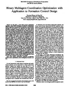
6. Simulation results 6.1 Simulations environment Figure 6. The trajectory of vehicle (one fixed obstacle)
The physical inspiration multi-agent model described in the previous section has been implemented based on the multi-agent platform 1 proposed by J.Ferber and O. Guknecht. This simulation is used to validate some characteristics of our multi-agent model. When the simulation program is running, the connecting component can automatically connect to the sensors installed on the vehicle by the TCP/IP interface (because the reactive multi-agent system commonly running on another computer that remote to the intelligent vehic le) in order to acquire the information such as the position, size, speed and mass (commonly proportional to the size of the obstacle) of the obstacles in front of the vehicle. Then the reactive multi-agent system will automatically calculates the speed vector and position vector of the vehicle in each time step according to the initial position and initial speed of the vehicle and finally finds the vehicle collision avoidance trajectory to control the speed and the orientation of vehicle.
obstacle agent in the environment. Just like an ant to find the shortest path for the food, when the vehicle faced one obstacle in front of it, there are two equal possibilities for the vehicle to choose from the left side or right side to avoid the obstacle, so there are two symmetrical trajectories emerged in the simulation process.
6.2 Simulations results analysis When the parameters of the multi-agent model are empirically configured by the following: the decision agent mass m=50 (which is equal to 1000kg in reality), the obstacle agent mass M=50 (which is equal to 1000kg in reality), the repulsion factor α=β=0.2, the friction factor λ=0.07, the perception range of decision agents r=10mm (which is equal to 25m in reality), the perception range to obstacle agents R=20mm (which is equal to 50m in reality), the simulation environment is defined by 100mm*100mm rectangle scope (which is equal to the 250m*250m space in reality), the size of the obstacle agent SI=1mm (which is equal to the 2.5m length in reality). We acquired the following simulations results in the situation of the fixed obstacles from Figure 6 to Figure 10. Figure 6 illustrates the avoidance trajectory of the vehicle when there are 300 decision agents and 1 fixed
1
Figure 7. The trajectory of vehicle (two fixed obstacles) Figure 7 illustrates the avoidance trajectory of the vehicle when there are 300 decision agents and 2 fixed obstacle agents in the environment. We can see the vehicle will form the different trajectory if the distance between two obstacle agents is different. The above one illustrates the trajectories of the vehicle when two obstacle are far enough (the distance between them is bigger than the size of the vehicle 2.5m length to pass through). It is nearly a straight line while not is because some interaction influences by the two obstacle agents. The lower one illustrates the trajectories of the vehicle when the two obstacles are near enough (the distance is
Madkit5, http://www.madkit.org
202
Authorized licensed use limited to: IEEE Xplore. Downloaded on April 1, 2009 at 09:46 from IEEE Xplore. Restrictions apply.
smaller than the size of the vehicle 2.5m to pass through).The calculation process of the trajectory can be seen in equation (7) and equation (8).
(it changes its position along the X coordinate by 10mm difference in the simulation environment, which is equal to 25m in reality). There are 300 decision agents and 1 fixed obstacle agent in the environment. We can see the vehicle will form the different trajectories if its initial position (comparing to the position change of the obstacle) is different. The middle ones illustrate the trajectories of the vehicle when the obstacle is just in front of it. The other ones show the trajectories of the vehicle when the initial position of the vehicle is moving along the left/right directions. We can see the farther of the distance between the obstacle and the vehicle the more straight-line liked of the trajectory of the vehicle because the vehicle needn’t to avoid the obstacle. On the contrary, the trajectory is more bended because the influence of the obstacle.
Figure 8. The trajectory of vehicle (three fixed obstacles) Figure 8 illustrates the avoidance trajectory of the vehicle when there are 300 decision agents and 3 fixed obstacle agents in the environment. We can see the vehicle will form the different trajectory if the distances among three obstacles are different. The above one illustrates the trajectories of the vehicle when the three obstacles are near enough (the distances among them are smaller than the size of the vehicle 2.5m to pass through). The lower one illustrates the trajectories of the vehicle when the distances between any two obstacles are far enough (bigger than the size of the vehicle 2.5m to pass through).
Figure 10. The trajectory of vehicle (changing the initial speed of the vehicle) Figure 10 illustrates the vehicle avoidance trajectories when the vehicle increases its initial speed vector along the Y coordinate by 0.4mm/s (which is equal to 1m/s in reality, the maximum speed is 2mm/s=5m/s in reality). There are 300 decision agents and 1 fixed obstacle agent in the environment. We can see from the Figure 10 the different trajectories if the initial speed of vehicle is different. The middle ones illustrate the trajectories of the vehicle at the speed 0.4mm/s (1m/s), the other ones show the trajectories of the vehicle when its speed changed from 0.8mm/s (2m/s) to maximum 2mm/s (5m/s). We can see from the Figure that the faster the speed of the vehicle, the more bended of the trajectories of the vehicle will be because the vehicle will change its direction earlier to avoid the obstacle. On the contrary, the trajectories are less bended and the vehicle will change its direction later to avoid the obstacle. In order to find the best solution to the collision avoidance control with different kinds of obstacles for the vehicle, we could also manually configure the parameters of our multi-agent model in the simulation environment.
Figure 9. The trajectory of vehicle (changing the initial position of the vehicle) Figure 9 illustrates the different avoidance trajectories when the vehicle dynamically changes its initial position
203
Authorized licensed use limited to: IEEE Xplore. Downloaded on April 1, 2009 at 09:46 from IEEE Xplore. Restrictions apply.
vehicle Packet Forwarding. IEEE Communications Society subject matter experts for publication in the IEEE GLOBECOM 2005 proceedings, pages 2762-2766, 2005 [5] A.NIETO, K DAGDELEN. Development and Testing of a Vehicle Collision Avoidance System Based on GPS and Wireless Networks for Open-Pit Mines. Application of Computers and Operations Research in the Minerals Industries, South African Institute of Mining and Metallurgy, 2003. [6] You Chung Chung, Steven L Olsen, Leonard Wojcik, Zhen Song, Chenghong He, Scott Adamson. Wireless Safety Personnel Radio Device for Collision Avoidance System of Autonomous Vehicles. IEEE, 2001. [7] Yin-Jun Chen, Ching-Chung Chen, Shou-Nian Wang, Han-En Lin, Roy C. Hsu. GPSenseCar-A Collision Avoidance Support System Using Real-Time GPS Data in a Mobile Vehicular Network. IEEE, 2004. [8] Ravipriya Ranatunga, Member, IEEE, Sisil Kumarawadu, Member, IEEE, Pawan Lingras, and Tsu-Tian Lee, Fellow, IEEE. A New Paradigm for Intelligent Collision Avoidance via Interactive and Interdependent Generic Maneuvers. IEEE International Conference on Systems, Man, and Cybernetics. Taipei, Taiwan, October 8-11, 2006. [9] Kim Hak-Jae, Kim Nam-Soo,K im Seung-Cheol, Lim Young-Do. The Design of Control of System for Collision Avoidance. ISIE, Pusan, KOREA, 2001 [10] Ulrich Lages, Collision Avoidance System for fixed Obstacles - Fuzzy Controller Network for Robot Driving of an Autonomous Vehicle. IEEE Intelligent Transportation Systems Conference Proceedings - Oakland (CA), USA , August 25-29, 2001 [11] Benjamin Mourllion, Alain Lambert, Dominique Gruyer, Didier Aubert. Collaborative Perception for Collision Avoidance. Proceedings of the 2004 IEEE,International Conference on Networking, Sensing E Control, Taipei, Taiwan, March 21-23. 2004. [12] Sudha Arora and A. K. Mittal. A Priority Based Conflict Resolution Approach for Automated Guided Vehicles. Proceedings of the 2006 American Control Conference Minneapolis, Minnesota, USA, June 14-16, 2006 [13] Charles-Antoine Brunet, Ruben Gonzalez-Ru bio, Mario T6treault. A Multi-Agent Architecture for a Driver Model for Autonomous Road Vehicles. CCECW/CCGEI, 1995. [14] Dong Eui Chang, Shawn C. Shadden, Jerrold E. Marsden, and Reza Olfati-Saber. Collision Avoidance for Multiple Agent Systems, Proceedings of the 42nd IEEE Conference on Decision and Control. Maui, Hawaii USA, December 2003 [15] Olivier Simonin and Franck Gechter. An EnvironmentBased Methodology to Design Reactive Multi-agent Systems for Problem Solving. D. Weyns, H. Van Dyke Parunak, and F. Michel (Eds.): E4MAS 2005, LNAI 3830, c_Springer-Verlag Berlin Heidelberg, pages. 32–49, 2006. [16] F. Gechter, V. Chevrier and F. Charpillet. A Reactive Agent-Based Problem-Solving Model: Application to Localization and Tracking. ACM Transactions on Autonomous and Adaptive Systems, Volume 1, Issue 2: Pages 189–222. December 2006.
7. Conclusion This paper is aimed to present a reactive multi-agent approach to the vehicle collision avoidance problem. In this paper, we propose a multi-agent model, in which we change the vehicle and its real world into the environment that the agents faced with. A reactive multiagent system is defined in the environment which includes two main reactive agent roles – the decision agent and the obstacle agent. The agents’ interactions behaviors are inspired by Newtonian physics. For each agent interacted in the environment, interactions are only limited to a perception scope, while it can realize the decision process by the continuously global behavioral observation of the decision agents’ organization. The collision avoidance stability emerges as a global result of the individual interacted decision agents. The avoidance control strategy for the vehicle stems finally from calculating the trajectories of the vehicle based on the decision process of the reactive multi-agent system. The simulations results illustrate the essential characteristics of this kind of solution: adaptability (tuning the model’s physical parameters), flexibility (changing the number of the obstacles) and reliability (changing the position and the speed of the vehicle). However, there are some problems to be considered in the future such as how to deal with the moving obstacles and how to optimize the model parameters to acquire the better adaptation to different kind of obstacles. Therefore we are now running into the further research on the following two points: (1) Finding the vehicle collision avoidance strategy in order to cope with the moving obstacles; (2) Finding the optimization configuration parameters of the multi-agent model in order to adapt to different kinds of obstacles.
References [1] Chih-Chiun Lai, Wen-Hsiang Tsai. Location Estimation and Trajectory Prediction of Moving Lateral Vehicle Using Two Wheel Shapes Information in 2-D Lateral Vehicle Images by 3-D Computer Vision Techniques. Proceedings of the 2003 IEEE International Conference on Robotics & Automation Taipei, Taiwan, September 14-19, 2003. [2] C. L. Robinson, H.-J. Sch¨utz, G. Baliga and P. R. Kumar. Architecture and Algorithm for a Laboratory Vehicle Collision Avoidance System. 22nd IEEE International Symposium on Intelligent Control Part of IEEE Multiconference on Systems and Control Singapore, 1-3 October 2007. [3] Yang Ying, Wei Ximing. The Research of Collision Avoiding System Based on Millimeter Wave and Image Processing Technique. IEEE, 2006 [4] Raymond Tatchikou, Subir Biswas, Francois Dion. Cooperative Vehicle Collision Avoidance using Inter-
204
Authorized licensed use limited to: IEEE Xplore. Downloaded on April 1, 2009 at 09:46 from IEEE Xplore. Restrictions apply.