Application Patterns for Computer-Based Systems Design Reuse Miroslav Švéda Department of Computer Science and Engineering Technical University of Brno, Czech Republic
[email protected] Abstract This paper deals with Computer-Based Systems (CBS) architecture components, called as application patterns, and with their employment for design reuse. The first two sections introduce the concept of application patterns, relate it to the well-known object-oriented design abstractions, and specify the appropriate terminology. Employing application patterns that demonstrate the concrete examples of reusability, the kernel of this contribution presents two case studies, which are based on real design projects. The paper focuses on identification, creation, and initial classification of reusable application patterns while retrieval, adaptation, and storage reuse tasks are only mentioned at the conclusion as a launching research.
1. Introduction Simpson, Rowe, Rossak, and Leaney present in [15] the following statements that can stand for a motto of this paper: „Architecture has many meanings, and general agreement on system architectures is not widespread. The same can be said for terms used for referring to architectures, their representations and their method of development/design.“ Respecting the CBS architecture terminology proposed in the above cited contribution, this paper strives to refine some concepts to fit design reuse. Every real-world CBS design stems from decisions based on an application domain knowledge that includes facts about previous design practice. Evidently, such decisions relate to systems architecture components, called in this paper as application patterns, that determine not only required system behavior but also presupposed implementation principles. Application patterns should respect those particular solutions that were successful in previous relevant design cases. While aimed at the system architecture range that covers more than software components, the application patterns correspond in many features to reusable patterns [22, 2], design patterns [4], and frameworks [3] for object-oriented design. Because they are closely related to particular application domains, the syntax of application patterns can hardly be referred to in an
application-independent way; concurrently, they appear to be more concrete from the semantic viewpoint. Thus, to enable reusability, we restrict slightly application domain variability while a design methodology, including a design language, remains unspecialized. There are other related concepts such as use cases [7, 10], architectural styles [14], or templates [20] that could be utilized for the purpose of this paper instead of introducing a novel notion; nevertheless, we strive to deal with the system architectures of embedded applications without any implicit reference to object-oriented modeling or to other special features contemplated in specifications of the above mentioned notions. To relate application patterns to the previously introduced concepts more definitely, we briefly restate the main characteristics of those concepts, omitting their exclusive software and object orientation. Hence, a pattern describes a problem to be solved, a solution, and the context in which that solution works [8]. Patterns are supposed to describe recurring solutions that have stood the test of time. Design patterns are the micro-architectural elements of frameworks. A framework--which represents a generic application that allows the creation of different applications from an application (sub)domain [12]--is an integrated set of patterns that can be reused. While each pattern describes a decision point in the development of an application, a pattern language is the organized collection of patterns for a particular application domain, and becomes an auxiliary method that guides the development process (see the Alexander’s pioneer work [1], which belongs surprisingly to the field of buildings architecture).
2. Basic Concepts The slight modification of the concepts, which were originally introduced by Zave and Jackson for software engineering projects [24], complemented by suggested working terms according to [15], can serve the purpose of this paper. Although the resulting terminology is not as complete and refined as the relevant utilization of the requirements terminology published by White in [21], it is simple and
precise-enough to satisfy the aims of this contribution--of course, the succeeding sections use also additional necessary concepts specified in [21]. The basic terms, excerpted from [24], can be restated as follows: • The environment is the portion of a real world relevant to the design project. • The machine is a CBS that will be constructed and connected to the environment, as a result of the design project. • A statement (assertion, property) in the indicative mood describes the environment as it would be without or in spite of the machine. • A statement (assertion, property) in the optative mood describes the environment as we would like it to be because of the machine. • A requirement is an optative property, intended to express the desires of the customer concerning the design project. • A statement of domain knowledge is an indicative property, intended to be relevant to the design project. • A specification is an optative property, intended to be directly implementable and to support satisfaction of the requirements. Let S be the set of specifications, R be the set of requirements, and K be the relevant domain knowledge for a design project. Then S and K must be sufficient to guarantee that the requirements R are satisfied: S, K V R This assertion is satisfied when S, K, and R are consistent with each other. Moreover, an implementation, I, of the specifications, S, must satisfy the requirements, R. The primary role of domain knowledge, K, is to bridge the gap between requirements, R, and specifications, S. Requirements that are not specifications are always converted into specifications with the help of domain knowledge. Application patterns, which embody domain knowledge, deal both with specifications and implementations. In fact, a precise characterization of the difference between specifications and requirements depends on precise location of the interface between the machine and environment. However, there are no strict boundaries between machines and their environments in general: they depend also on application patters employed. A design reuse process involves several necessary reuse tasks that can be grouped into two categories: supply-side and demand-side reuse [13]. Supply-side reuse tasks include identification, creation, and classification of reusable artifacts. Demand-side reuse tasks include namely retrieval, adaptation, and storage of reusable artifacts. For the purpose of this paper, the reusable artifacts are represented by application patterns.
Comparing to systems design reuse, software design reuse is currently highly published topic, see e.g. [9], [6], [5], [25], [16]. Namely the state-dependent specification-based approach discussed in [25] inspired the application patterns handling presented in the current paper. The next sections of this contribution describe two case studies, which are based on implemented design projects, using application patterns that enable to discuss the concrete examples of application patterns reusability. The paper focuses on supply-side reuse tasks while demand-side reuse tasks, together with formal specification means, are mentioned at the conclusion as topics of the launching research.
3. Case A: Petrol Dispenser Control System The first case study pertains to a petrol pumping station dispenser with the machine in form of a distributed, multiple microcomputer counter/controller [17]. To succeed the prescribed systems requirements, the final CBS has to respect also the following non-functional requirements [21]: real-time, accuracy, and safety properties.
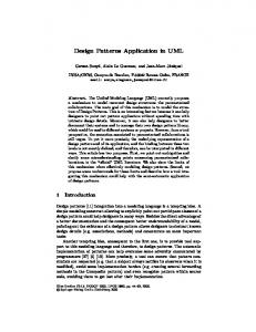
3.1 Functional specifications A dispenser control system communicates with its environment through two classes of inputs/outputs. The first class describes an interface with volume meter (input), pump motor (output), and main and by-pass valves (outputs) that enable full or throttled flow. The timing for this class is driven by flow velocity and precision requirements for measurement. The second class of inputs/outputs models human interface, which must respect human-physiology timing constants. This class contains release signal, unhooked nozzle detection, and product's unit prices as inputs; as for outputs, volume and price displays belong to this class. The first employed application pattern is the two-level structure proposed by Xinyao et al. [23]: the higher level behaves as an event-driven component, and the lower level behaves as a set of real-time interconnected components. The behavior of the higher level component can be described by the finite-state automaton with states "BLOCKED-IDLE," "READY," "FULL FUEL," "THROTTLED," and "CLOSED" and with inputs "release," (nozzle) "hung on/off," "close" (the preset or maximal volume achieved), "throttle" (to slow down the flow to enable exact dosage), and "error" depicts the overall behavior timed, in this case, by external events exclusively. Hence, we can model the behavior of this automaton by the first two state sequences on Fig. 1. The states "FULL_FUEL" and "THROTTLED" appear to be hazardous from the viewpoint of unchecked flow because the motor is on and the liquid is under pressure--the only nozzle
Timed by external events: →
READY
hung off
→
READY
hung off
BLOCKED-IDLE
release
BLOCKED-IDLE
release
→
FULL_FUEL
error
→
FULL_FUEL
throttle
READY
hung off
READY
hung off
→ →
→
FULL_FUEL
hung on
→
→
FULL_FUEL
throttle
→
BLOCKED-IDLE THROTTLED
→
hung on
BLOCKED-IDLE
BLOCKED-ERROR THROTTLED
→
error
BLOCKED-ERROR
Fig. 1. High-level state sequences of petrol dispenser valve controls an issue in this case. Also, the state "READY" tends to be hazardous: when the nozzle is unhooked, the system transfers to the state "FULL_FUEL" with flow enabled. Hence, the accepted fail-stop conception necessitates the detected error management in the form of transfers to the state "BLOCKED-ERROR," see the last two state sequences on Fig. 1. To initiate such transfers for issue blocking, the error detections in the hazardous states are necessary. On the other hand, the state "BLOCKED-IDLE" is safe because the input signal "release" can be masked out by the system that, when some failure is detected, performs the internal transition from "BLOCKED-IDLE" to "BLOCKED-ERROR." Fuel measurement and flow control represent the main functions of the hazardous states. The next applied application pattern, incremental measurement, means the recognition and counting of elementary volumes represented by rectangular impulses, which are generated by a photoelectric pulser. The maximal frequency of impulses and a pattern for their recognition, depending on electromagnetic interference characteristics, define both behavioral and performance timing constraints. The lower-level application patterns are in this case noise-tolerant impulse detector and checking reversible counter. The first one appears to be an clock-timed impulserecognition automaton that implements the periodic sampling of the input with values 0 and 1. This automaton with n states recognizes an impulse after n/2 (n>=4) samples with the value 1 followed by n/2 samples with the value 0, possibly interleaved by induced error values, see the timed-state sequence for the case of n=4 on Fig. 2. For the sake of fault-detection requirements, the incremental detector and transfer path are doubled.
Consequently, the second, identical noise-tolerant impulse detector appears necessary. The subsequent lower-level application pattern is the checking reversible counter, which starts with the value (h+l)/2 and increments or decrements the value according to the "impulse detected" outputs from the first or second recognition automaton. Overflow or underflow of the pre-set values of h or l indicate an error. Another counter that counts the recognized impulses from one of the recognition automata maintains the whole measured volume. The output of the letter automaton refines to two displays with local memories not only for the reason of robustness (they can be compared) but also for functional requirements (doubleface stand). The display refreshment subsides to a different timing mechanism, dependent on the physiologic constants of human sight.
3.2 Refined system architecture Resulting architecture has to guarantee also a broad applicability. This requirement leads to a multi-purpose device for petrol, octane mixture, petrol and oil mixture, or high speed diesel-oil issue, for the attendant station or for the selfservice station with cashier or with debit or credit automaton or slot machine. One function enables the fuel amount or the cash amount to be preset either by the cashier (central management system) or by the customer at the dispenser (preset unit). The implementation of the system is based on a distributed architecture with optionally two or three simple microcontrollers. The main microcontroller, M, implements the volume meter, dose/cash counter, main display service,
Timed by local clock: (0,q1)inp=0 →...inp=0 →(i,q1)inp=1 →(i+1,q2)inp=0 → ...
→(j,q2)inp=1 →(j+1,q3)inp=1 →...
inp=1
(m+1,q1) i, j, k, m are integers; 0 < i < j < k < m
Fig. 2. Low-level timed-state sequence of impulse recognition
→(k,q3)inp=0 →(k+1,q4)inp=1 → ... inp=1 n0/IMP ... →(m,q4)
inp=1
→
and stand driver, including flow control. The auxiliary microcontroller pre-processes the volume impulses of both the possible liquids and implements testing and checking functions. The preset unit processor, P, when installed serves both preset keyboard and display and calculates a volume equivalent if the pre-setting is in cash. Next, an I/O watch-dog application pattern is designed to guard the equivalent main display increments with respect to the volume impulses. The detailed system design respects hard-real-time limits for impulse inputs and preset fuel-dose completion. The presence of the preset unit and/or central cashier system has to be transparent for the rest of the control system software; hence, that requirement influences the corresponding interprocessor communication protocol.
3.3 Fault maintenance application patterns The danger of explosion in the case of uncontrolled petrol flow is eliminated by the following hard kernel items: nozzle with hydraulic shut-off, hooked nozzle mechanical blocking, and cashier administration. To prevent unregistered flow, the fail-stop conception used appraises as more acceptable the forced blocking of the dispenser with frozen actual data on displays instead of an untrustworthy issue. On the other hand, because permanent blocking or too frequently repeated blocking is inappropriate, the final implementation must employ also fault avoidance techniques. The application patterns, so far introduced stepwise, interfere so that they accomplish the consequent application pattern, fault management based on fail-stop behavior approximation, in the form of (a) hazardous state reachability control and (b) hazardous state maintenance. In all safe states ("BLOCKED-IDLE," "CLOSED," and "BLOCKEDERROR"), any fuel flow is disabled by power hardware construction; in the same time, the contents of all displays are protected against any change required by possibly erroneous control system. The system is allowed to reach hazardous states ("READY," "FULL_FUEL," and "THROTTLED") when the processors successfully passed the following tests: start-up checks, unit prices comparison, interprocessor communication initiation, and all-or-nothing voting about correct processing of all installed microcontrollers. The hazardous state maintenance includes doubled input path check for a main product impulses, mixture ratio check for secondary product, and I/O watchdog check.
4. Case B: Multiple Lift Control System The second case study deals with the machine as a multiple lift control system based on a dedicated multiprocessor architecture [18]. Again, to succeed the prescribed systems requirements, the final CBS has to respect
also the same dynamic system properties as for the previous case study: real-time, accuracy, and safety.
4.1 Functional specifications The multiple lift control system governs the operation of N identical lifts servicing an M-story building; for this purpose, it interacts with the environment in the following way. Every lift cabin includes a control panel with one button for each floor, an emergency button, a key-lock handler for attendantmode traffic, and a numerical display. These inputs/outputs have to respect human physiological constants only. Other inputs and outputs in the lift cabin involve load sensor, door driver, door position detector, and gate optical barrier, of course, with individual timing. On each floor (except ground and top) there are two buttons, one to request a lift going upwards and the other for going downwards, course lights, arrival-time interval display, and acoustic signalization with the same timing requirements as lift cabin control panel. The position and speed of each lift are detected and they are controlled by lift drive. This group of inputs/outputs requires special attention because of short-time hard limits. An incremental measurement device for position evaluation of a lift cabin in a lift shaft is specified in more detail to demonstrate reusability. The applied application pattern, incremental measurement, means in this case the recognition and counting of rectangular impulses that are generated by an electromagnetic or photoelectric sensor/impulse generator, which is fixed on the bottom of the lift cabin and which passes equidistant position marks while moving along the shaft. The device is dedicated to support both (a) cabin position and speed control by communicating the actual position value to a drive controller and (b) lift maintenance by displaying the actual position. For the sake of safety requirements, the device has to be equipped by fault detection mechanisms. The device communicates with its environment through three classes of inputs/outputs. The first class describes an interface with the impulse generator and the drive controller as inputs. The timing for this class is driven by maximal cabin speed and by precision requirements for position measurements. The second class contains the communication output to the drive controller, which is timed according to control requirements. The third class contains a display with position indication as a human interface, which must respect human-physiology timing constants. For the demonstration, we restrict our attention to the first class inputs from impulse generator and drive controller and to the third class display output only. So, the first input, I, contains the values 0 or 1 that are altered with frequency equivalent to the cabin speed. The second input, D, contains the values "up," "down," or "idle."
initialization
→
position_indication
→
fault_indication
Fig. 3. High-level state sequence of position-measuring device
The output, P, resembles to the absolute position of the cabin in the shaft. The next employed application pattern is again the twolevel structure: the higher level behaves as an event-driven component and the lower level behaves as a set of real-time interconnected components. The behavior of the higher level component can be described by the state sequence on Fig. 3. and by the corresponding finite-state automaton. The specification of this level can be developed by refining the state position_indication into lower level automata. The behavior of the lower level can be described by three communicating, individually timed automata. The first automaton models the noise-tolerant impulse detector, timed by its local clock that defines a sampling interval. This interval must conform not only to the maximal speed and the distance of position marks but also to a pattern of samples for impulse recognition, depending on the electro-magnetic interference characteristics of the environment. Let the fitting pattern, with a proper timing, is represented by '1100'; then, adequate behavior for an impulse recognition can be described by the timed-state sequence with a constant timing defined by sampling instants in equal time intervals, see Fig. 2. The information about a detected impulse is sent to the counting automaton that can also access the indication of the cabin movement direction through the input D. The counting automaton communicates an actual position value to the display automaton. The display automaton comprises only two states: position indication and fault indication. The display refreshment subsides to a timing mechanism dependent on the physiologic constants of human sight. For the sake of faultdetection requirements, the impulse generator and the impulse transfer path are doubled. Consequently, a second, identical noise-tolerant impulse detector appears necessary. The subsequent application pattern is the checking reversible counter, which starts with the value (h+l)/2 and increments or decrements the value according to the "impulse detected" outputs from the first or second recognition automaton. Overflow or underflow of the preset values of h or l indicate an error. This detection process sends a message about a detected impulse and the current direction to the counting automaton, which sends a position message to the display. To guarantee the overall fault detection capability of the device, it is necessary also to consider checking the counter and the display. This task can be maintained by an I/O watchdog application pattern that can compare input impulses from the sensor/impulse generator and the changes of displayed value; the appropriate automaton performs again reversible counting.
4.2 Refined system architecture The complete system architecture can be refined to the following hierarchical structure. An external serial bus interconnects N identical lift controllers and a dispatcher station; in addition, each lift controller embodies a dedicated distributed system with an internal serial bus connecting a shaft controller, M floor controllers, and a cabin controller. The shaft controller is a multiprocessor comprising the scheduling processor and the drive control processor communicating through a common memory, two communication processors enabling to access the external and internal serial busses, and two simple watchdog processors. The behavior of each lift is planned by its scheduling processor using both global master directives, which consider orders from floors, and local orders from the lift cabin--the global master, elected among all active scheduling processors during the initialization phase, obtains also information about orders from all cabins to improve task allocation efficiency. For each shaft controller, the scheduling processor and the drive control processor share, in two-port RAM, the data structures describing the lift state (position, speed, direction, load, and error status), the list of orders to be serviced including allowed time limits, and the next serviced floor.
4.3 Fault maintenance application patterns The approach used accomplishes consequent application pattern, fault management based on fail-stop behavior approximation, in the form of (a) hazardous state reachability control and (b) hazardous state maintenance. In safe states, the lift cabins are fixed at any floors. The system is allowed to reach any hazardous state when all relevant processors successfully passed the start-up checks of inputs and monitored outputs and of appropriate communication status. The hazardous state maintenance includes operational checks and, for shaft controller, two watchdog processors performing consistency checking for both execution processors. To comply with safety-critical conception, all critical inputs and monitored outputs are doubled and compared. When the relevant signals differ, the respective lift is either forced (in case of need with the help of an substitute drive if the shaft controller is disconnected) to reach the nearest floor and to stay blocked, or (in the case of maintenance or fire brigade support) its services are partially restricted. The basic safety hard core includes mechanical, emergency brakes. On the
other hand, because permanent blocking or too frequently repeated blocking is inappropriate, the final implementation must employ also fault avoidance techniques. The other reason for the fault avoidance application stems from the fact that only approximate fail-stop implementation is possible.
References
5. Application Patterns Reuse
2
Domain knowledge is inherent in proper application patterns. Undoubtedly, to develop and reuse effectively an application pattern, the essence of a specific but reusable real-world (sub)domain knowledge must be discovered, evaluated, and specified. Apparently, reusable application patterns enable to introduce efficiently the system architectures supporting dependable computing classes such as hard real-time embedded systems across diverse application (sub)domains. The reused upper-layer application patterns presented above include namely (1) incremental measurement, (2) twolevel (event-driven/real-time) structure, and (3) fault management based on fail-stop behavior approximations. The reused lower-layer application patterns are exemplified by (4) noise-tolerant impulse detector, (5) checking reversible counter, and (6) I/O watchdog. The above presented case studies, which demonstrate the possibility to reuse such application patterns, are in fact excerpted from realized design cases. The application patterns, originally introduced as „configurations“ in the project of petrol pumping station technology [17], were effectively reused for the project of lift control technology [18].
1
3 4 5 6
7 8 9 10
11
6. Conclusions This contribution is a position paper launching the research of both formal specifications and knowledge-based support for the development of industrial CBSs. The formal tools considered initially encompass finite-state automata and temporal logics for discrete-event systems, and timed automata, real-time temporal logics, and an asynchronous specification language for real-time systems [19]. The first considered paradigm for knowledge-based support will be case-based reasoning that was studied by this research group in another application context, see [11]. Initial experiments discovered some difficulties in the retrieval of state-dependent specifications of application patterns: the problem is how to measure the similarity of statebased specifications in which the number of states should not be the key attribute. The primary idea appears to measure the similarity by the topology of associated state-transition graphs. Hopefully, the next paper (for the ECBS’2000?) will bring more definite results.
12 13 14 15
16 17
C. Alexander. A Pattern Language: Towns / Buildings / Construction. Oxford University Press, 1977. P. Coad and E.E. Yourdon. Object-Oriented Analysis. Yourdon Press, New York, 1990. M.E. Fayad and D.C. Schmidt. Object-Oriented Application Frameworks. Communications of the ACM, 40(10), 32-38, 1997. E. Gamma, R. Helm, R. Johnson, and J. Vlissides. Design Patterns--Elements of Reusable Object-Oriented Software. Addison-Wesley, 1995. S. Henninger. An Evolutionary Approach to Constructing Effective Software Reuse Repositories. Transactions on Software Engineering and Methodology, 6(2), 111-140, 1997. L.J. Holtzblatt, R.L. Piazza, H.B. Reubenstein, S.N. Roberts, and D.R. Harris. Design Recovery for Distributed Systems. IEEE Transactions on Software Engineering, 23(7), 461-472, 1997. L. Jacobson. Object-Oriented Software Engineering: A User Case-Driven Approach. ACM Press, 1992. R.E. Johnson. Frameworks = (Components + Patterns). Communications of the ACM, 40(10), 39-42, 1997. R. Mili, A. Mili, and R.T. Mittermeir. Storing and Retrieving Software Components: A Refinement Based System. IEEE Transactions on Software Engineering, 23(7), 445-460, 1997. B. Regnell, M. Andersson, and J. Bergstrand. A Hierarchical Use Case Model with Graphical Representation. Proceedings of IEEE Conference and Workshop on Engineering of Computer-Based Systems, Friedrichshafen, Germany, IEEE Computer Society Press, Los Alamitos, California, 270-277, 1996. M. Švéda, O. Babka, and J. Freeburn. Knowledge Preserving Development: A Case Study. IEEE Proceedings of the International Conference and Workshop Engineering of Computer-Based Systems'97, Monterey, California, IEEE Computer Society Press, Los Alamitos, California, 347-352, 1997. H.A. Schmid. Systematic Framework Design by Generalization. Communications of the ACM, 40(10), 48-51, 1997. A. Sen. The Role of Opportunity in the Software Reuse Process. IEEE Transactions on Software Engineering, 23(7), 418-436, 1997. M. Shaw and D. Garlan. Software Architecture. Prentice Hall, 1996. H. Simpson, D. Rowe, W. Rossak, and J. Leaney. Computer Based Systém Architecture - An IEEE ECBS TC Architecture Focus Group Discussion Paper. Proceedings of the IEEE Conference and Workshop on Engineering of Computer-Based Systems’98, Maale Hachamisha, Israel, 359-364, 1998. A. Sutcliffe and N. Maiden. The Domain Theory for Requirements Engineering. IEEE Transactions on Software Engineering, 24(3), 174-196, 1998. M. Švéda. Embedded System Design: A Case Study. Proceedings of the IEEE Symposium and Workshop
18
Engineering of Computer-Based Systems'96, Friedrichshafen, Germany, IEEE Computer Society Press, Los Alamitos, California, 260-267, 1996. M. Švéda. An Approach to Safety-Critical Systems Design. In: F. Pichler and R. Moreno-Diaz (Eds.): Computer Aided Systems Theory--EUROCAST'97, Springer-Verlag, LNCS 1333, 34-49, 1997.
19
20 21
22 23
24 25
M. Švéda. Asynchronous Specification Language and Design with Local Time." Proceedings of the IEEE Conference and Workshop on Engineering of Computer-Based Systems’98, Maale Hachamisha, Israel, IEEE CS Press, 256-263, 1998. K.J. Turner. Relating Architecture and Specification. Computer Networks and ISDN Systems, 29(4), 437-456, 1997. S. White. Requirements Capture and Analysis Prior to Modeling. Proceedings of the IEEE Conference and Workshop on Engineering of Computer-Based Systems, Monterey, California, IEEE Computer Society Press, Los Alamitos, California, 10-17, 1997. R. Wirfs-Brook, B. Wilkerson, and L. Wiener. Designing Object-Oriented Software. Prentice Hall, 1990. Y. Xinyao, W. Ji, Z. Chaochen, and P.K. Pandya. Formal Design of Hybrid Systems. In: H. Langmaack, W.-P. de Roever, and J. Vytopil, editors, Formal Techniques in RealTime and Fault-Tolerant Systems, Springer-Verlag, 738-755, 1994. P. Zave and M. Jackson. Four Dark Corners of Requirements Engineering. ACM Transactions on Software Engineering and Methodology, 6(1), 1-30, 1997. A.M. Zaremski and J.M. Wing. Specification Matching of Software Components. ACM Trans. on Software Engineering and Methodology, 6(4), 333-369, 1997.