setts Institute of Technology. This machine used vacuum tubes and hardwired
logic cir- cuits, and defined “numerical control” to mean control based on coded ...
Applications of Adaptive Control to Machine Tool Process Control A. Galip Ulsoy and Yoram Koren ABSTRACT: This paper describes recent research in the area of machine tool process control where adaptive control theory has been applied. First, the process control problem in metal-cutting operations is described, and the important research problems of online tool wear estimation and adaptive process control are introduced. The research in these areas is then summarized, and some results are presented from the research work of the authors, including results from recent laboratory experiments.
Introduction The control of machine tools for metal cutting began in the late 1940s with simple plugboard controllers and copying machines that used servos to follow and magnify the tracing motions on a model of the desired part. Gradually, these early devices evolved into numerically controlled machine tools. The first numerically controlled machine tool was a three-axis milling machine developed initially under a U.S. Air Force contract by the Parsons Company of Traverse City, Michigan, and completed in 1952 in the Servomechanisms Laboratory at the Massachusetts Institute of Technology. This machine used vacuum tubes and hardwired logic circuits, and defined “numerical control” to mean control based on coded numerical information. With advances in computer technology, an onboard computer replaced the hardwired logic and gave rise to the computer numerically controlled (CNC) machine tools of the late 1960s. During the past two decades, the number of CNC machine tools in commercial use has increased dramatically. A common drawback of these machines is that their process control variables, such as the machining feeds and speeds, must be prescribed by a part programmer and, consequently, depend on his or her process knowledge and experience. In order to minimize the chance of a tool failure or unacceptable part quality, the
A. Galip Ulsoy is an Associate Professor and Yoram Koren is a Professor in the Department of Mechanical Engineering and Applied Mechanics, University of Michigan, Ann Arbor, MI 48109-
part programmer must consider the most advene cutting conditions (which will, in practice, seldom occur) and select conservative values of the process control variables. Conservative choices for the process control variables are also necessitated by the part programmer’s lack of complete prior knowledge of a process as complex as metal cutting. Because conservative values of the process control variables are selected, the typical production rates achievable are not as high as ideally possible. Thus, although CNC systems control the relative position between the tool and workpiece, they do not control the metal-cutting process itself. The process planning, typically done by the part programmer, is generally accomplished offline based on “worst-case” cutting conditions. The availability of the processing power of an onboard CNC computer has stimulated research into automating the control of metalcutting processes. Thus, the control system automatically would select the required values of the process control variables based on on-line process measurements. Such systems have come to be referred to as “adaptive control” systems in the manufacturing literature, although they are not necessarily adaptive in the sense commonly used in the control literature [l], [2].In this paper, these systems will be referred to as process control systems rather than adaptive control systems. Consider the result one might expect from such a process control strategy applied to milling a workpiece under variable depth or variable width of cut conditions. The higher feed rate values achievable at the lowdepth (or width) portion of the cut with process control results in a higher metal removal rate (MRR), where w is the width of cut (in.), a the depth of cut (in.), V the feed velocity of the milling cutter ( i n h i n ) , and the MRR is then given in cubic inches per minute. MRR = waV
(1)
The feed ratef(in./rev) is related to the feed velocity V by the following, where N is the spindle speed (rev/min), and the integer p is the number of teeth on the milling cutter.
2125.
Studies of the economic benefits achievable with process control typically cite improvements in productivity of from 20 to 80 percent over conventional machining [3]. In the next section, the basic concepts and significant research associated with such process control systems are reviewed, and some of the problems with process control systems that have prevented their widespread adoption by industry are discussed. The first of these problems is identified as the need for reliable on-line tool wear sensing, and the research in this area is described in the following section, which focuses, in particular, on tool wear sensing research based on the application of adaptive state-estimation methods. A second major problem is the poor process controller performance, which can result from process parameter variations. This issue is discussed in some detail in the subsequent section, which describes the application of adaptive control theory to the process control problem in both turning and milling operations. The paper concludes with a brief summary and conclusions.
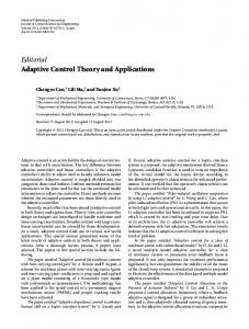
Review of Process Control in Metal Cutting The idea of process control in metal cutting was first developed seriously in a wellknown research project for milling conducted at Bendix in 1962-1964 undera U.S. Air Force contract [4], [ 5 ] . This system, schematically illustrated in Fig. 1, was designed to perform an on-line maximization of an economic index of performance to determine the required feed rate and spindle speed in a milling operation based on measurements of the cutting torque, tool temperature, and the tool vibration. The optimization problem also included constraints on the physical variables. The index of performance can be expressed as the following, where TWR is the tool wear rate (in./min), WOthe terminal allowable width of flank wear (in.), C , the cost of machine and operator per unit time ($/min), C, the cost of tool and regrind per tool change ($/change), and t l the tool changing time (min):
J ( f , N ) = MRR/[CI
+ (Cif1
+ C*P)(TWR)~WlI (3) 0272-1708/89/0200-0033$01 00 0 1989 IEEE
June 1989
33
economic process optimization problem is dominated by the need to maintain product Spindle-speed commands
. -
quality (e.g., dimensional accuracy and/or Machine tool
Sensors
I
Corrected feed rate
A
I\
1
Corrected spindle speed Process controller
Sensor outputs
Performance index
1 Performance subsystem Tool wear constants
Fig. I .
electronics Conditioned sensor outputs
Bendix adaptive control optimization system for milling [ 3 ] .
The constant 0 is an adjustable parameter in the range 0 5 0 I 1, which determines the type of performance index J . If 0 = 1, then J represents the reciprocal of the cost per unit produced; if 0 = 0, then J represents the production rate; and for intermediate values of 0,J represents a weighted combination of these two objectives, which can be adjusted to represent the profit (i.e., maximum production with minimum cost). The Bendix system is an example of what typically is referred to as an adaptive control optimization system. The Bendix system was implemented successfully in the laboratory, but never worked well in an industrial environment. With the possible exception of the system for grinding reported in [6], which is being used in an off-line mode in industry, the authors are not aware of any successful commercial applications of adaptive control optimization systems. The poor acceptance of such systems in industry primarily is due to the need for an on-line tool wear sensor for implementation of an adaptive control optimization strategy [3]. The Bendix system tries to bypass this problem by estimating the TWR from torque and temperature measurements. This on-line tool wear estimation problem has generated considerable research over the past two decades and is described in some detail in the following section. Although full adaptive control optimization systems could not be implemented successfully, suboptimal systems, which can
34
surface finish). In these situations, most of the benefit of an adaptive control optimization system can be obtained through the use of geometric adaptive control with a GAC strategy 171, [8]. If the part dimensions and surface roughness can be measured, then the process control strategy can be expressed as: “based on the dimensional measurement, introduce a tool offset to compensate for the tool wear and adjust the feed rate to produce parts at the reference surface roughness value determined from the maximum allowable surface roughness constraint.” The GAC systems have also not found widespread industrial acceptance, although the GAC system described in [9] is currently being implemented in a manufacturing facility.
provide many of the benefits of the optimal systems, have been developed. These are typically categorized as adaptive control with constraints (ACC) systems and geometric adaptive control (GAC) systems. Most commercial process control systems in industrial use today use adaptive control with constraints and are of the ACC type [ 11. These systems take advantage of the fact that, under certain cutting conditions, the process optimization problem has an optimal solution, which occurs on a constraint boundary. For example, in rough cutting operations, the economic objective function typically is dominated by the need to maximize the MRR, which, in turn, requires the highest possible feed rates consistent with the tool breakage constraint. Thus, for a particular tool geometry, this can be expressed as the following process control objective: “adjust the feed rate to maintain the reference cutting force, which is determined as the highest possible cutting force such that the tool is not in danger of breaking.” There are ACC systems commercially available for turning, milling, and drilling, but they are not very widely used. The reason for their poor industrial acceptance is the potential problems of controller instability and tool breakage, which can occur due to process parameter variations. These problems have generated a considerable amount of research, which is described in detail in a subsequent section. Similarly, in a finishing operation, the
Research in Tool Wear Estimation As described in the previous section, one of the key steps in implementing an adaptive control optimization system is the on-line measurement of tool wear. Figure 2 illustrates the two dominant types of wear-flank wear and crater wear-observed on a carbide cutting insert in turning operations. Flank wear typically has initial accelerated wear followed by a linear wear region and then accelerated wear at the end of tool life. Crater wear, on the other hand, increases exponentially with time. Depending on the cutting condition, either of these two wear types
Wear on Carbide Inserts
Flank wear \
Crater wear
/
.Crater wear -cut
~~
~
Fig. 2. Typical conjguration for j u n k wear and crater wear.
IEEE Conrrol Svsrems Mag,mnc
might be dominant. There has been considerable research directed at this problem over the past two decades. Direct sensing using optical methods, such as computer vision, is difficultto implement on-line and cannot be used when the tool is in the cut. Various indirect methods have been proposed using measurements of force, motor current, tool vibration, acoustic emissions, etc. [IO]-[ 121. These indirect strategies, however, suffer from the need to separate the effect of wear from the effects of other factors on the measured signal. Thus, various signal processing methods have been suggested and applied [ 131. For example, statistical techniques such as the cumulative percent deviation method described in [ I l l gives good results under steady cutting conditions. When cutting conditions such as feeds and speeds change, it then becomes more difficult to separate their effects from the effects of wear. Of course, such changing cutting conditions are always expected with the use of process controllers. One promising approach to the problem of tool wear estimation under varying cutting conditions is the use of a process model of tool wear [ 141, 1151. Such a model was first proposed by Koren [I61 for the thermally and mechanically activated mechanisms, which are predominantly responsible for wear on the flank side of the tool. Similar models have also been proposed for the crater wear, which occurs at the tool-chip interface, but this appears to be a much more difficult modeling problem [17]. Danai and Ulsoy [I81 combined these models reported in the literature into a statevariable description of tool wear in a turning operation and formulated the wear estimation problem as a state-estimation problem. Their model, formulated for force measurement in a turning process, consisted of three nonlinear state equations and an output equation:
+
(l"/V)i~fi
~
f
= l K , ( F COS a , ) / ( f d )
(4)
wfz= K?&exp [-K3/(273
+ Of)]
(5)
io,. = K4FV exp [-Ks/(273
+ OJ1
(6)
where
+ K7wf"'
0,
=
K6 V"Y"'
0,
=
K,FV"'f "'d"'
F = [Kgf"'(l
-
K,,cx,) - KII -
+ K,3dWf - K,4w,
(7)
(8) Vld
(9)
In these equations, wfl represents the mechanically activated flank wear component arising from abrasion between the workpiece and the flank side of the tool, wfz denotes
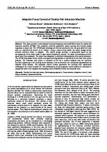
the thermally activated flank wear component, and total flank wear, wf.is simply the sum of the two flank wear components. w,. represents the crater wear; Of and 0,. are tool temperatures at the tool-workpiece and toolchip interfaces, respectively; and F is a measured cutting force component. The cutting speed is V , the feed isf, d is the depth of cut, a, is the effective rake angle, and lo is a constant. Since the coefficients K, and the exponents n, appearing in the model equations are not accurately known, an adaptive observer was proposed to cany out simultaneous parameter and state estimation. The adaptive observer design was developed based on a linearized wear model during the constant wearrate portion of the flank wear curve. Danai and Ulsoy [ 191, [20] evaluated this adaptive observer for tool wear sensing using a series of analytical, simulation, and laboratory studies. The results of these studies were mixed, in that the adaptive observer did not give good results when used with the full model given in Eqs. (4)-(9). However, the adaptive observer worked reasonably well when the cutting conditions were selected so that one type of wear (either flank wear or crater wear) dominated. Results of laboratory experiments are shown in Fig. 3 for the case with crater wear only. The linearized discrete-time implementation of Eq. (6) with no flank wear leads to a model of the following form [20]:
The parameter c must be determined off-line from direct wear measurements for a particular tool-workpiece combination. When cutting first begins, w,(O)equals 0 and d can be estimated from F(O)/f(O).Subsequently, the parameters a and b can be estimated on-line from force measurements. Note that a and b will be slowly time varying, due to the linearization of Eq. (6), as the cutting conditions change. The estimated values of a and b from actual machining tests are shown in Fig. 3(a). In Fig. 3(b), the estimated crater wear using the adaptive observer is compared to direct optical crater wear measurements made using a tool-maker's microscope. Research is continuing in an attempt to extend the model-based approach to multiwear conditions, to utilization of a full nonlinear formulation, to consideration of tool breakage as well as tool wear, and to variable-depth-of-cut cutting conditions [2 I]1231.
June 1989
-
W
a 10 Time. t (mln)
I
.f i
Measured values
(b)
0.25 _-A
0.20
I 5
20
r/-
0.15
I
6
-
0.10 /'
m E
f 0.05 W
J
,-
10 Time, f (min)
2.0
Fig. 3. Laboraton. experiment from [20]. (a) estimated parameters; (b) estimated crater wear.
Adaptive Process Control in Metal Cutting In the previous section, which reviews process control in metal cutting, it was noted that ACC systems can suffer from problems of instability and/or tool breakage due to process parameter variations. This was demonstrated in laboratory experiments, as reported in [24]. Their laboratory system is an ACC-type process controller for turning based on cutting force feedback and manipulation of feed rate. A simple integral control strategy is used in the process control. The instability or breakage problems occur due to the fact that the gain, K,,, of the cutting process model varies with changes in depth of cut, workpiece material properties, and other normal process variations as follows: ,F+F=KJ
(12)
The process time constant 7 also varies, but not very significantly. An adaptive, or vanable-gain, version of this algorithm was also implemented. The variable-gain controller used on-line estimation of the process gain K,, to adjust the integral controller gain [25]. Typical experimental results in Fig. 4 show good performance with the variable-gain scheme despite process variations. The depth of cut, d , increases from 2 to 4 to 6 mm during the cut, and the feed rate, f , is reduced by the controller to maintain the cutting force, F, at the reference value of 1500 N . Note that the integral controller gain, K, ,
35
~-
F.
N
i
1
f
o[fl
05
L--’
0 2 4 6 8 1012 14 16 18 2 0 2 2 2 4 2 6 28
-
t . sec
Fig. 4. Experimental results for the variable-gain adaptive control with constraints system for turning [25]. is varied based on the estimated value, K,,,, of the process gain, K,,. Adaptive process controllers for various metal-cutting operations have also been investigated by other researchers (e.g., see [ I], [7], [26]-[28]). Here, we describe a model reference adaptive force controller for milling, as reported in [29], [30]. For a particular laboratory milling machine, they conducted modeling experiments to obtain a dynamic model of the following form, and determined that the model parameters (