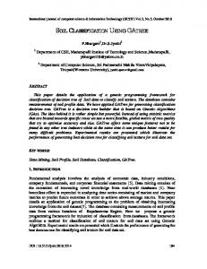
Ave., Alexandria, LA 71302;. 3. MZB Technologies, LLC 519 20 th. Street SW Jamestown, ND. 58401. Keywords and Phrases. GPS, GIS, precision, site-specific, ...
APPLYING NITROGEN SITE-SPECIFICALLY USING SOIL ELECTRICAL CONDUCTIVITY MAPS AND PRECISION AGRICULTURE TECHNOLOGY Eric D. Lund1 Maurice C. Wolcott2 Glenn P. Hanson3 1
Veris Technologies, 601 N. Broadway, Salina, KS 67401; 2LSU Ag Center, 8105 East Campus Ave., Alexandria, LA 71302; 3MZB Technologies, LLC 519 20th Street SW Jamestown, ND 58401 Keywords and Phrases GPS, GIS, precision, site-specific, soil EC, electrical conductivity, variable rate, N, nitrogen, yield, soil sampling, cotton, corn, wheat, over-application, soil texture, yield goal, productivity, rank growth, management zones Abstract Soil texture varies significantly within many agricultural fields. Soil physical properties such as soil
texture have a direct effect on water-holding capacity, cation-exchange-capacity, crop yield, production capability, and nitrogen (N) loss variations within a field. In short, mobile nutrients are used, lost, and stored differently as soil textures vary. A uniform application of N to varying soils results in a wide range of N availability to the crop. N applied in excess of the crop usage results in a waste of the grower’s input expense, a potential negative effect on the environment, and in some crops a reduction of crop quality, yield, and harvestability. Inadequate N levels represent a lost opportunity for crop yield and profit. The GPS-referenced mapping of bulk soil electrical conductivity (EC) has been shown to serve as an effective proxy for soil texture and other soil properties. Soils with a high clay content conduct more electricity than coarser textured soils, which results in higher EC values. This paper will describe the EC mapping process and provide case studies of site-specific N applications based on EC maps. Results of these case studies suggest that N can be managed site-specifically using a variety of management practices, including soil sampling, variable yield goals, and cropping history. Synopsis This paper presents site-specific methods for determining N application rates. Included are case studies from three regions of the United States where commercial soil EC mapping, and variable rate N have been adopted by growers. In each example, the variable N rates are calculated using generally accepted principles for single-rate N, but are adapted to meet the site-specific needs of the field using advanced mapping technology currently available in precision agriculture. Presented at the 2nd International Nitrogen Conference on Science and Policy, Potomac MD, October 14-18, 2001
Introduction Determining the proper amount of nitrogen (N) to be applied to an agricultural field is a source of debate and discussion among growers, input suppliers, and researchers. Some commonly accepted methods for devising N rates for corn, wheat, and cotton production are: 1) the establishment of a yield goal which determines the overall N level needed for the crop to achieve that goal1,2, 2) soil sampling to determine the ability of the soil to supply a portion of the N needed by the crop2,3. 3) Local university research of N response functions. In addition, most growers’ decisions are also influenced by traditional fertilization practices in their area and by their own knowledge and experiences gained by working their land. In actuality, decisions on N rates are usually a combination of these methods. A potentially serious environmental and economic problem with any single N rate is that there are typically areas within a field which need a different amount than the uniform rate. As shown in Figure 1, available N as determined by soil sampling on a 0.3 ha grid, can vary significantly within a 50 ha field. A uniform rate based on a single sample from the low N areas would result in over-application on the areas already containing high N levels. Also, crop yields can vary widely within a field, and frequently these exhibit spatially structured patterns, as shown in Figure 2. Devising a single N rate based on one yield goal for this field would likely result in over-application to the areas which have shown over time to have lower yield potential.
Figure 1. Variability of N levels within a 50 ha field (0-60 cm depth; fall sampling) Figure 2. Variability of historical yield within a 10 ha field With the advent of precision agriculture technologies, such as global positioning systems (GPS), geographic information systems (GIS), and soil electrical conductivity (EC) mapping, growers and their consultants can soil-sample and record geo-referenced field characteristics with 1-3 meter accuracy. They are now beginning to apply N based on sub-field criteria, and varying rates to more closely meet the site-specific demands of the crop. Specifically, these tools can be used in a site-specific manner to improve N efficiency by assisting in: (1) Determining the availability of N in the soil, and (2) Estimating the amount of N needed by the crop. Materials and Methods In order to determine the N needs of a field, two questions about the spatial variability of the field must be answered: where does the yield potential vary, and where does N availability vary?
Each of the case studies presented here include the use of soil electrical conductivity (EC) mapping as a layer of soils information used to help address these questions. Soil N Availability The usefulness of soil EC in precision agriculture stems from the fact that it typically correlates well with soil texture: sands have a low conductivity, silts have a medium conductivity and clays have a high conductivity4. (Figure 3). In turn, the texture of soil strongly affects N activity in it and N movement through it 5,6.
FIGURE 3. Soil electrical conductivity depends on soil texture and other properties. The rapid mapping of a field’s soil EC can be accomplished by mobilized equipment like the Veris 3100 Soil EC Mapping System. As the cart is pulled through the field, the system acquires conductivity measurements and geo-references them using a GPS receiver. When used on 15 to 20m swaths at speeds up to 12 k/h, the system produces between 40 and 100 samples per ha. Contact methods, like that used by the Veris model 3100, use at least four electrodes that are in physical contact with the soil to inject a current and measure the voltage that results (Figure 4).
Figure 4. The Veris 3100 soil conductivity mapping system employs two arrays to investigate soil at two depths, 0-25 cm and 0-75 cm. Mapping the soil EC of a field can serve as an effective proxy for mapping the soil texture of the field, at a significantly reduced cost (Figure 5). While it is not yet possible to predict actual N levels directly from soil EC, it is possible to use soil EC as a surrogate measurement for the properties that directly affect N levels7. Soil EC maps can be used effectively for guiding soil sample locations and in a GIS as a geo-referenced soils layer.
Figure 5. Clay content and soil conductivity from a 16 ha Iowa field. N Needed for Crop Production Soil EC measurements are closely correlated with soil texture and nutrient holding capacity4,8, which are important factors in crop yield. Electrical conductivity has shown to relate closely to other soil properties that can influence productivity, including organic carbon content7, cationexchange-capacity (CEC)8, soil depth9, water holding capacity/drainage10, and salinity11. Therefore, EC maps often correlate well with crop yield maps 12. If low yielding areas are stable across multiple years of various growing conditions, and if those same areas correlate with soil conditions that typically accompany lowered crop yields, a grower may elect to set a lower yield goal in these areas, and reduce his N inputs accordingly. (Figure 6)
Figure 6. Maps of EC, historical crop yields, and a yield goal-based N rate from a 65 ha field. Results The following examples describe how crop producers in three different regions of the United States are practicing these innovations. In each of these case studies, the traditional whole-field approach to N management for that cropping system is fine-tuned using site-specific technology. Case Study No. 1 The first case study is from the non-irrigated, predominately cereal grain producing area of the Dakotas. The customary N practice in this area is to apply one rate to an entire field, based on a single sample of soil cores composited from various areas of the field. These cores are typically
collected from soil depths of 0-180 cm, and may be segmented at various levels within the sample profile. Research has shown there is considerable within-field variability in the available N levels, and that this variability is related to the movement of water and nutrient movement in and through the landscape3. Research has also shown that the sampling density needed to properly capture this variability would require a .4 ha grid13. Due to the expense of the deep nitrate sampling and the relatively low value of the commodity crops being produced, soil sampling at this intensity is not practical. An alternative is to sample the field guided by layers of information that correlate to water and nutrient movement, such as topography and soil EC, and to nutrient usage, such as yield maps and remote crop imagery3. This approach has been commercialized by MZB Technologies of Jamestown North Dakota on more than 20,000 ha since 1998. Under the MZB system, soil EC, precise elevation data, crop vigor imagery and other layers of data are collected. (Figure 7)
Figure 7. Soil EC, topography, and crop imagery from a 65 ha field. These data are clustered into zones of similarity using a GIS program. Soil sample locations are determined using the grower’s input and the zone map (Figure 8).
Figure 8. Zones and sampling points. The field is sampled, the soil samples are composited within each zone, and are laboratory analyzed. Bar graphs are produced which show the different N levels in each zone (Figure 9). A N rate is set for each soil zone, taking into account the grower’s input, soil sample results, and yield goals. (Figure 10).
Figure 9. Nitrate N from each zone in Figure 8 (kg/ha; 0-61 cm sampling depth) Figure 10. N recommendation (Urea kg/ha) Growers have been encouraged to leave uniform rate test strips in their fields and compare them using yield monitors to the results of variable rate N. Results from 33 sites in Brown county, South Dakota, and Stutsman, Lamoure, and Dickey counties in North Dakota have shown advantages for the variable rate approach: Wheat has averaged increases of 11.3% in yield, 0.75% in protein, and $8.20/ha net margin. Average increases on corn were 15.9% on yield, 0.70% on protein, and $16.81 in net margin per ha. Soybeans had average yield gains of 9.9% and net margin of $10.17/ha. N usage has been affected as follows: growers who had been soil sampling previously on a whole-field basis have found their overall N rates remain about the same, with N being re-distributed to zones that require differing N rates. Growers who had not been soil sampling, and who had taken a low-input approach, have found a crop response to increasing their N rates. Growers who had not been sampling previously, and who had taken an aggressive approach to fertilization, have typically been able to reduce N inputs. Case Study No. 2 The second case study is from central Kansas. In this 70 cm annual rainfall area, growers are making a transition from continuous wheat production to include grain sorghum, soybeans, and corn in their non-irrigated crop rotation. Soil sampling for N is typically not attempted, because it is assumed by growers that the relatively mild and moist winters cause what N remains unused by previous crops, to be lost over winter. Organic matter levels are in the 1-2% range, so only a small percentage of a crop’s need for N is provided by mineralization. If N rates are to be finetuned in this region with available technology, it will need to be accomplished by adjusting crop yield goals. The example field used in this case study is an 18 ha field that has soil texture and topography variability typical for fields in this region. Yield data from multiple years of various crops reveal consistently low yields in areas of this field, corresponding with eroded side slopes. High yielding areas are the depositional areas at the bottom of these slopes. These productivity patterns are stable across a range of weather, including years with optimal rainfall (Figure 11).
Figure 11. 1997, 1998, 1999 yields from an 18 ha Kansas field. The areas of high EC correspond to the eroded side slopes, due to the higher clay content subsoil being at or near the surface. Lower EC readings are found in the higher-yielding depositional areas, where the depth of the silt-loam top-soil is greater (Figure 12).
Figure 12. Soil EC and normalized three-year yield on elevation map A scatter-plot for EC and the three-year normalized average yield from this field shows a statistically significant correlation, at the 1% significance level (Figure 13). An effective method of analyzing bi-variate data such as yield and soil EC data, is the boundary line analysis14,15. This method involves dividing EC data from a field into equal ranges, or bins. In this case, ten ranges were used. The five top yielding points for each soil EC range were selected, which represent the highest yields in each of the ten soil EC ranges. These fifty points are plotted and a regression line is fitted to them (Figure 14). This upper boundary line represents the maximum yield for each soil EC range. While there may be a number of factors causing yields to be lower than the boundary, the maximum yield for each soil EC range is delineated by the boundary line, for the crop year(s) being considered. When this approach is applied to the three years of yield and EC data for the Kansas field in this case study, the results show a nearly linear reduction in historical productivity as soil EC increases (Figure 14).
Figure 13. Scatter Plot of EC and 3 year normalized average yield data Figure 14. Boundary line plot of EC and 3 year normalized yield data
This information is then used to create a yield goal map with a reduction in N for those areas that have demonstrated lowered productivity (Figure 15).
Figure 15. Yield goal map based on three-year historical yields and soil EC data The analysis method described above utilizes a gridding or rasterizing of the EC and yield data in order to identify the historical maximum productivity. Other EC and yield data analysis methods are being used by consultants and growers to delineate productivity potential. The most common of these involves creating management zones based on EC. These polygons of homogeneous soil EC are queried for their average and maximum historical yields, and those results help establish a yield goal for each zone. Before adjusting N rates based on historical yields, it is important insure that previous yields were not N-limited, by conducting N strip trials to evaluate the N efficiency of the various soils in the field. Case Study No. 3 The third case study is from the cotton-growing area of south Louisiana, in the Mississippi Delta. The traditional N practice here is for growers to use the university extension recommended rates for cotton, which is a single rate for the field based on soil type and texture, crop rotation, and cotton variety15. Growers and their consultants fine-tune these single rates based on their experience. Due to the nature of the alluvial soils in the Delta, there are frequently wide variations of soil texture within a field. This causes a large disparity of N availability, especially when cotton follows heavily-fertilized corn in the crop rotation. Over winter, denitrification removes most of the N from the clayey soils, but silt loam and sandy loam soils often retain significantly more of the applied N into the next cropping season, in some cases enough to supply the complete N needs of the following cotton crop. On the fertile alluvial soils of the Delta, over-application of N in cotton production often results in more adverse effects than under-application. N applied in excess of the needs of the cotton crop results in vegetative, or rank plant growth rather than increased boll production, as well as reduced fiber quality. Rank growth must be controlled by application of growth regulating chemicals to reduce yield losses due to boll rot and insect damage. Increased rates of defoliant chemicals at harvest time may also be required as a result of the rank growth. The wasted N and the additional chemicals have a negative effect on the economic returns to the growers and likely the environment as well. To improve this situation, Lambert Crop Consulting of Innis, Lousiana is working with its clients to site-specifically apply N to cotton fields. Their approach begins with using a soil EC map to define the areas of contrasting soil texture (Figure 16). Using the grower’s and consultant’s knowledge of the field to help interpret the soil EC data, and taking into account the crop
rotation, an N recommendation is devised (Figure 17). Note: this process does not include soil sampling. If the grower and consultant were not familiar with the fields and areas of historical rank growth, a sampling step would likely be necessary.
Figure 16. Soil EC data from a 15 ha Louisiana field Figure 17. N recommendation map The results of N applications are shown in Figures 18a-c. The effect of applying a single rate is evident in the 135 cm tall cotton in coarse-textured soil (Figure 18a). Figures 18b and 18c are photographs taken at the locations marked on the N recommendation map shown in Figure 17. These low EC and high EC soils received the variable rate N shown in Figure 17, and cotton in both fields are 95 cm tall, the ideal height for cotton at this stage.
Figures 18a,b,c. 18a: Cotton growing in sandy soil that received a single rate of 50 kg of N/ha. 18b: A sandy soil area of the adjacent field that received 0 N. 18c: A clayey soil area in the same field that received 100 kg of N/ha. The results of this approach are encouraging. On the 15 ha field shown in Figure 17, more than 10% of the field received zero N and more than half of the field received less than a conventional uniform rate. Since a 30% over-application of N to cotton has been shown to result in profit reductions of $10-30 per ha15, growers have significant financial incentives for adopting a sitespecific N program. As a result, grower interest in the program is increasing, with about 1,000 ha enrolled in the system in 2001.
Summary While research continues on the subject of proper N usage, it is feasible to fine-tune N management by applying the accepted methodologies for whole-field N rates to sub-field areas, using precision agricultural technologies. Commercial input suppliers and growers have already begun the process, and as economical and environmental pressures increase, the incentive to further develop the practice will increase as well. References 1. Hoeft,R., Nafziger,E., Johnson, R., and Aldrich, S. (2000) Modern Corn and Soybean Production, 1221-1223 2. Ferguson, R., Hergert, G., Penas, E. (2001) Nutrient Management for Agronomic Crops in Nebraska, 73-75 3. Franzen, D. and Kitchen, N. (1999) Developing Management Zones to Target N Applications, PPI Site-Specific Management Guideline No. 5 4. Williams, B. and Hoey, D. (1987) The Use of Electromagnetic Induction to Detect the Spatial Variability of the Salt and Clay Content of Soils. Australian Journal Soil Research, 25, 21-27. 5. Gaines, T., and Gaines, S. (1994) Soil Texture Effect on Nitrate Leaching in Soil Percolates Common. Soil Sci. Plant Anal., 25 (13 &14) 2561-2570 6. Buchholz, D. (1993) N in Missouri Soils University of Missouri Extension Guide G09174 7. Jaynes, D., Novak, J., Moorman, T., and Cambardella,C. (1994) Estimating Herbicide Partition Coefficients from Electromagnetic Induction Measurements. Journal of Environmental Quality, 24, 36-41. 8. Doolittle, J., Suddduth, K., Kitchen, N., Indorante, S. (1994) Estimating Depth to Claypans Using Electromagnetic Induction Methods. Journal of Soil and Water Conservation, 49, 572575. 9. Jaynes, D. (1996) Improved Soil Mapping Using Electromagnetic Induction Surveys. Proceedings of the 3rd International Conference on Precision Agriculture, pp 169-179. 10. Rhoades, J., Corwin, D. (1992) Determining Soil Electrical Conductivity-depth Relations Using an Inductive Electromagnetic Conductivity Meter. Soil Science Society of America Journal, 45, 255-260. 11. Lund E., Christy, C., Drummond, P. (2000) Using Yield and Soil Electrical Conductivity (EC) Maps to Derive Crop Production Performance Information Proceeding of 5th International Conference on Precision Agriculture 12. Franzen , D. (1999) Soil Sampling and Variable Rate Fertilizer Application North Dakota State University Extension Publication SF-1176 13. Kitchen, N., Sudduth, K., Drummond, S. (1999) Soil Electrical Conductivity as a Crop Productivity Measure for Claypan Soils. Journal of Production Agriculture 12:607-617 14. McBratney, A., and Pringle, M. (1997) Spatial Variability In Soil—Implications For Precision Agriculture. Precision Agriculture 1997 3-31 15. Boquet, D., and Moore, S. (2000) N Management for Different Soils and Cropping Systems. Proceedings of the Beltwide Cotton Conference Volume 1:40-42