Figure 3. Call connection UCM. Stubs: OH. do offhook processing at caller end (different plug-ins if .... that is present when a user is subscribed to 3-way calling.
Applying Use Case Maps to Multi-agent Systems: A Feature Interaction Example R.J.A. Buhr†, M. Elammari†, T. Gray‡, S. Mankovski‡ Carleton University† and Mitel Corporation‡ email: {buhr, elammari}@sce.carleton.ca, {tom_gray, serge_mankovski}@mitel.com
Abstract Multi-agent systems are emerging as a potential solution to the problem of constructing flexible network-based software. A characteristic of such systems is that wholesystem behaviour patterns emerge from the combination of many details in many agents, in sometimes intricate ways. Understanding the big picture by composing the details is often difficult and designing the details to achieve some desired whole-system behaviour pattern can easily become a cut-and-try exercise. To help solve these problems, we offer use case maps (UCMs) to provide a first-class representation of whole-system behaviour patterns, at a level above details. To illustrate the approach, we apply it to a classical distributed system problem of a kind that agent systems must be capable of solving, namely feature interaction in telephony.
1. Introduction Multi-agent systems are emerging as a potential solution to the problem of constructing flexible network software. The problem they aim to solve is the impossibility of building an entire system around predefined requirements for application functionality, user interactions, communication protocols, available resources, current technology, and so forth. All of these things may change over time. The agent solution is to build intelligence into special software components called agents, to enable them to work at a metalevel, compared to ordinary software, that will enable them to adapt and evolve. An example of a metalevel is provided by the well known BDI (Beliefs, Desires, Intentions) model [15]. This paper and a companion paper [10] come out of a research project on high level design and prototyping of agent systems [4]. The contribution of this paper is to illustrate the concepts described in the companion paper [10] by applying them to specific example, namely the feature interaction problem. We show by example how the visual UCM representations help human understanding of agent systems as systems. We point the way towards using this understanding to develop agent internal models capable of resolving conflicts, but do not develop this in detail for the examples (it is a subject of
current research). The current agent community may be said to be taking the following approach to designing desired system behaviour into multi-agent systems: Design the internal, metalevel logic of individual agents for adaption and evolution, implement the result, and then stand back and hope that satisfactory behaviour will emerge at the system level. Example scenarios of intended system behaviour may be developed during the design process, but using techniques that produce complex and unwieldy descriptions that do not scale and do not yield sufficient insight into system properties. For example, presenters of agent systems at a recent agent conference (PAAM97, London, April 97) typically solved the problem of explaining their systems by displaying sequences of boxarrow diagrams, in the style of object interaction diagrams that are popularly used for software design. The boxes represented agents and the arrows represented message paths. Sequences of diagrams are needed because the agents and the relationships among them may change over time. We are developing an approach employing use case maps (UCMs) [5][6][7][8][11] that enables humans to understand and specify agent system behaviour as a first class artifact, independent of the internal metalevel (or software) logic of the agents. The approach is high level and defers details, while providing a framework for filling in details and for understanding the relationship of details to the big picture. We hope that this approach will help customers and system designers to communicate better about requirements, provide a systematic starting point for transforming requirements into metalevel agent logic (and hence into software implementations), and help with system evolution by providing a high level reference for making detailed changes. The intent is not to sweep everything away and start anew, but to supplement conventional techniques from the agent domain and the software engineering domain with new techniques that give a clearer system picture. The UCM technique is, to the authors’ knowledge, unique at its level of abstraction. In both the agent community and other communities, such as the object-oriented community, people use more detailed visual techniques to describe systems. For example, Kendall
[14] models agent systems using object-oriented-style diagrams that require commitment to agent-centric details (e.g., pairwise interactions via messages, pairwise inheritance relationships). There are many tools in the object-oriented community that support modelling of systems at this level of detail (for example, [2][16]). In the agent community, the Clearlake tool [13] specifically supports design of agent systems at a similar level of detail. From the perspective of this paper, workflow models (e.g., as discussed and applied by Kendall [14]) are a variation of data flow models. As Kendall points out, there are nuances that make them useful for agent systems, but the following two basic properties of data flow models remain: they do not show continuity of causal paths through a system; and they do not provide any direct or easy means of describing one of the central features of agent systems, self modification at the system level. Otherwise, techniques in the agent community, such as COOL [1] and Shoham’s AOP [17], represent agents formally with logic, with no visual representation. Visual representation is well known to be needed for human understanding. A suitable high level visual representation, such as use case maps, can be used as a starting point for generating more detailed visual descriptions and/or formal descriptions, as we propose here. This paper presents examples of the application of UCMs to a classical distributed system problem of a kind that multi-agent systems must be capable of solving, namely feature interaction in telephony [12]. One of the major problems in dealing with feature interaction is the lack of techniques to describe it in a first class manner against the background of the system as a whole, rather than in terms of details. The result is a danger of the feature interaction problem becoming lost in the details. UCMs help with this problem by representing feature interactions in a first-class way, above the level of details. Historically in telephony, feature interaction problems have been solved by ad hoc, detailed methods associated with particular combinations of features. Better techniques are starting to emerge [3], but are still at the level of details—needed is a first class description of conflict resolution problems, such as feature interaction, above the level of details, to drive the solutions. Feature interaction may take a number of forms, but the form we examine here has the characteristic that whole-system behaviour patterns for individual features come into conflict when events conspire to combine features. The conflict must somehow be resolved by building avoidance or detection into the fabric of the system. When the system is a multi-agent one, this means that the agents must, in a collective fashion, avoid the problem, or recognize and resolve it. Building the appropriate logic into the agents to do this requires that the designer of the logic understand the feature interaction problem in firstclass terms, at the system level. We show how UCMs may be employed for this purpose.
2. Use case maps (UCMs) A companion paper [10] describes the elements of UCMs that are particularly useful for our purposes here. However, to enable this paper to be read independently, here is a short summary. UCMs (Figure 1) give a high level view of causal sequences in a system as a whole, as paths. The causal sequences are called scenarios. UCMs show paths for scenarios, not actual scenarios, but enable a human viewer to reason about actual scenarios. In general, UCMs may have many paths (the figure only shows one, for simplicity). The causality expressed by the paths is understood by humans, not necessarily by individual components of the system. r1
r2
r3
C2
C1
C3
Figure 1. Example of a UCM. A filled circle indicates a start point of a path, the point where stimuli occur causing activity to start progressing along the path. A bar indicates an end point, the point where the effect of stimuli are felt. Paths trace causal sequences between start and end points. The causal sequences connect responsibilities, indicated by named points along paths (e.g., r1, r2 and r3). Paths are superimposed on rectangular boxes representing operational components of the system (e.g., C1, C2 and C3), to indicate where components participate in the causal sequences. The basic assumption is that stimulus-response behaviour can be represented in a simple way with paths. This is a very common characteristic of the types of systems with which we are concerned. The result is a pathcentric view of a system, rather than a conventional component-centric view. UCMs may be decomposed using a generalization of responsibilities called stubs (e.g., S in Figure 2). r1 C1
r2 C2
S C3
Figure 2. A UCM with a stub. Stubs may be positioned along paths like responsibilities but are more general than responsibilities in two ways: They identify the existence of sub-UCMs and they may span multiple paths (not shown). Stubs enable us to draw UCMs that give a high level overview of the general trend of paths, while leaving localized meanderings that might obscure the big picture to sub-UCMs shown in separate diagrams. A plug-in may involve additional system components not shown in the main UCM. A key feature of stubs for agent systems is the ability to represent dynamically pluggable behaviour patterns with them (analogous to plans, in agent terminology [10]). A stub may have alternative plug-ins
that may be selected according to different system conditions at the time a scenario reaches the stub. Stubs of this kind are shown in dashed outline to distinguish them from stubs that are only used for static path decomposition. There are other useful UCM tricks for agent systems, such as slots for dynamic components that may be created or moved around, but they are outside the scope of this paper (see [10]).
3. Feature interaction examples Here we aim to show how UCMs help, during design, in understanding scenario conflict problems at the level of whole systems. Our assumption is that better understanding will lead to better design. Our aim here is to point the way towards the beginnings of a process to help human designers develop details of agent metamodels in a systematic way from UCMs. The process itself is outside the scope of this paper. In any case, developing such a process is a subject of current research.
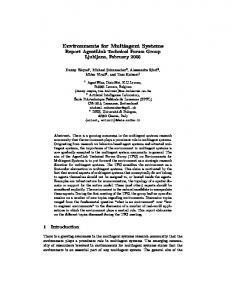
Figure 3 presents only part of the picture, namely a CALL path going from left to right. In general, each agent may be either a caller or answerer, each will have both an OH and a PCR stub, and paths may go in both directions. Figure 4 continues setting the stage by showing how the agents in Figure 3 would be initialized with the features that we shall use as examples (about to be described). The assumption is that each agent may subscribe any combination of these features. For all but one of these features, installation means creating a plug-in for the feature and putting it into a feature pool for either the OH or PCR stub (the small arrow with the “+” beside it conveys this meaning). Features could also be loaded from some repository. The remaining feature is threeway calling (3WC). This is an example of an activealways feature, meaning that, upon subscription, it is available all the time. The plug-in for such a feature is created and moved directly into an always-active stub in each agent (3WC here). done
3.1. UCM models of features
SUBSCRIBE
OH
+
Basic call scenario OH pool +
Figure 3 begins setting the stage by showing a UCM for a basic call scenario between two user agents in some larger system of agents (see [9] for a more general call scenario). Assume that user agents are the representatives inside the system of human users in the application environment. Among other responsibilities, the user agents store user information and preferences.
Typical User Agent
PCR pool
PCR
3WC +
Figure 4. Initialization. CALL
OH
Caller User Agent
PCR
ring
Answerer User Agent
This initialization sets up the agents so that the CALL path of Figure 3 can be realized (an implicit precondition of the CALL path is that the initialization has been performed). Figure 5 shows the assumed meaning of the CALL path in relation to the initialized elements. When the CALL reaches OH, a plug-in is selected from
Figure 3. Call connection UCM. Stubs:
OH
PCR ring
CALL
OH. do offhook processing at caller end (different plug-ins if via a phone or a call view on a computer screen) PCR. process connection request (different plug-ins can be selected, depending on system conditions as seen by the agent)
The precondition of the CALL scenario is that a user wants to place a call. The postcondition is that the phone rings at the answerer end. The CALL path begins with an OH (Off Hook) stub to perform offhook processing at the caller’s end. The path continues with a PCR (Process Connection Request) stub at the answerer’s end. The path ends with the phone ringing at the answerer end.
OH
Caller User Agent
PCR
Answerer User Agent
Figure 5. Assumed standard pattern for all features and stubs. the OH pool and moved into the OH stub (the small arrows mean selection and movement). The same things occurs at the PCR stub. Which plug-in is selected
depends in either case upon conditions at the time. The 3WC stub is not part of a basic CALL scenario. The pattern of Figure 5 for selecting plug-ins for stubs will be assumed for all subsequent UCMs. Default PCR plug-in Figure 6 shows the default plug-in for the PCR stub in the absence of features, i.e. the figure describes the default behavior when the answerer is not subscribed to any feature. In this and all remaining plug-in diagrams, a path that enters a stub in the main UCM enters the plug-in at the point labelled enter and exits the plug-in to return to the main UCM at the point labelled exit. The plug-in starts with a simple fork, called an orfork, that indicates alternative scenario paths. If the user is busy, the path labeled busy is followed and the caller is notified that the answerer is busy. The fork after that, with the bar across it, called an and-fork, indicates that the scenario proceeds concurrently along two paths. One path leads to a RING stub (for which no plug-in is provided here) that notifies the answerer, for example by ringing a phone device; the other path notifies the caller of call progress. The cross hatching underneath the Caller User Agent indicates that this is an actual component in the context of the stub (other components of plugins are, by default, formal ones that are created when plugging in occurs).
Caller User Agent
TCS RING exit
enter TCS list check
caller notified
refused
notify
ringing
Precondition: Answerer is not busy Figure 7. Terminating Call Screening (TCS) plug-in for PCR stub. Automatic re-call (ARC) plug-in for PCR stub Figure 8 describes the PCR plug-in that would be selected when the answerer is subscribed to the automatic re-call feature (ARC), and system conditions at the time of entry to this stub select this feature. This plug-in has additional start and end points relative to ones labelled enter and exit. These identify environmental events that are treated in a special way by this feature after it has been activated. The ARC feature is activated when the an arriving call scenario finds the answerer busy. It adds the caller’s number to a list that will be dialled automatically later on, when the user is no longer busy. The path begins by ARC Caller User Agent
Caller User Agent enter notify
busy
ARC list add
caller notified
on hook
get
notify
RING exit ringing
enter
timed-out path
RING off hook exit
Figure 6. The default PCR plug-in.
Terminating call screening (TCS) plug-in for PCR stub Figure 7 describes a plug-in that would be selected for the PCR stub when a user is subscribed to the terminating call screening (TCS) feature and the conditions at the time of entering the stub select this feature. The plugin brings in a new system component labelled TCS to do the processing for this feature (this might be a TCS process or thread triggered by the answerer user agent—the actual nature of this component is not important for our purposes here). The TCS feature checks the caller’s number and then, if the number is not on the answerer’s screening list, call connection is allowed to proceed as in Figure 3. If the caller’s number is on the answerer’s screening list, then the caller is notified that the answerer is refusing connection. The precondition of this scenario is that the answerer is not already busy with another call.
Precondition: Answerer is busy Figure 8. Automatic Re-Call (ARC) plug-in for PCR stub. and-forking two concurrent paths. The bottom path notifies the caller that the answerer is currently busy and will be called back when the answerer is available. The top path adds the caller’s number to the ARC list and waits for an on-hook event. The filled circle along the path is a waiting place and the path leading from the off-hook event to this waiting place indicates the trigger that clears the waiting condition. When the on-hook event occurs, the path continues by getting the caller’s phone number from the ARC list and ringing the answerer’s phone. The ARC feature waits, with time-out, until the answerer performs an off-hook operation. If the off-hook event happens within the time-out period, then the caller is notified, by special ringing, that the answerer is accepting the call.
Call forwarding (CF) plug-in for PCR stub Figure 9 describes the PCR plug-in that would be selected when the answerer is subscribed to the call forwarding feature (CF), and system conditions at the time of entry to this stub select this feature. In Figure 9, the CF feature performs the forward responsibility which causes the incoming call to be forwarded to another user agent, which will be responsible for processing the call request.
enter
Answering Service
AC
Forwarded To User Agent
CF
selected when the answerer is subscribed to the answer call (AC) feature, and system conditions at the time of entry to this stub select this feature. The precondition of the path in Figure 11 is that the answerer end is busy with another call. In the figure, the AC feature performs the forward responsibility which causes the incoming call to be forwarded to the answerer’s answering service, which connects to the caller. .
enter
CNT
forward
exit
PCR
forward
exit
Precondition: Answerer is busy Precondition: CF is on. Figure 9. Call Forwarding (CF) plug-in for PCR stub.
Figure 11. Answer Call (AC) plug-in for PCR stub. Originating call screening (OCS) plug-in for OH stub
Call waiting (CW) plug-in for PCR stub Figure 10 describes the PCR plug-in that would be selected when the answerer is subscribed to the call waiting (CW), and system conditions at the time of entry to this stub select this feature. The precondition of the plugin is that the answerer end is busy with another call. The plug-in in Figure 10 shows two paths. When this plug-in is selected, the basic call scenario will follow the top path and the bottom path is followed when the event associated with it occurs in the future. The top path starts by alerting the answerer end of an incoming call and concurrently notifying the caller of the current call status. The bottom path shows how the answerer can connect to the second call by pressing the flash key. Pressing the flash key puts the current connection on hold and connects to the second call, shown respectively by the hold responsibility and the CNT stub (for which no plug-in is provided here). . Caller User Agent
CW
enter
alert
exit
Figure 12 describes the PCR plug-in that would be selected when the caller is subscribed to the originating call screening (AC) feature, and system conditions at the time of entry to this stub select this feature. The scenario path for the OCS plug-in begins with OCS list being checked. If the dialled number is in the caller’s screening list, then connection is refused. This shown on the path by the or-fork after the check responsibility. Otherwise the caller is allowed to connect to the dialled number. Caller User Agent OCS OCS list enter check alternate exit
denied
exit
Figure 12. Originating Call Screening (OCS) plug-in for OH stub.
notify CNT connected
hold
3-Way Calling (3WC) plug-in flash key pressed
Precondition: Answerer is busy
Figure 10. Call Waiting (CW) plug-in for PCR stub. Answer Call (AC) plug-in for PCR stub Figure 11 describes the PCR plug-in that would be
Figure 13 describes the active-always 3WC feature that is present when a user is subscribed to 3-way calling. The precondition of the 3-way calling scenario is that the 3WC subscriber is busy. The user can add a third party to the call by pressing the flash key; shown in diagram as an event. This will result in putting the current conversation on hold. The subscriber then can start a normal outgoing
call to connect to the third party. 3WC flash key pressed
OH
hold
connected
Preconditions: User is busy
Figure 13. 3-Way Calling (3WC) plug-in.
3.2. Feature Interactions The following feature interaction examples were selected for their instructiveness in this context from among many examples described in [12]. 1.
Inconsistent behavior among different plug-ins for the same stub Inconsistent behaviour may occur between plugins for the same stub in different agents, or in the same agent at different times. This is illustrated using the TCS and ARC features (Figure 7 and Figure 8). The interaction can be understood at a glance from the highlighted parts of Figure 14. At the top, we can see that when the TCS feature is active, the answerer is not busy and the caller’s number is in the answerer’s TCS list, the call is denied. At the bottom, we can see that when the ARC feature is active, there is no check of the answerer’s TCS list and a call originating from a number that is in the TCS list is not denied. Particular conditions in an agent will select one or the other of these plug-ins. If different agents, or the same agent, select different plug-ins they will exhibit inconsistent behaviour.
actions in the context of a whole system, and that this cannot but help the design of solutions. A glance at Figure 14 in the context of Figure 3 suggests that one obvious way (not the only way) to resolve this interaction is to put TCS at the beginning of any plug-in that involves another feature that may result in call connection. 2.
Unexpected behaviour among different selected plug-ins for different stubs Features activated in different places in a scenario may interact unexpectedly. An example that illustrates this deals with interactions between the originating call screening and call forwarding features. Let us assume that user agent A can call user agent B, but it can not call another user agent X (not shown in Figure 3) because X is on A’s screening list, while B is not. This is shown in Figure 15. The grey path going from A to X is labeled illegal, because A should never be able to connect to X as long as X on A’s OCS list. The actual path that A follows when it calls X is shown in Figure 16. However if B has call forwarding, B may forward A’s call to a number on A’s screening list, as shown in Figure 17. This violates the intend of originating call screening. We can see that even though A’s OCS was activated, A was connected to X. X
illegal
TCS
B
A CALL
ring
call denied
Figure 15. A cannot connect to X. ARC A CALL X call denied
call accepted
Figure 16. A’s OCS denies calls to X.
Figure 14. Inconsistent behavior when different plug-ins selected for the same stub. We suggest that UCMs like these offer a designer a an effective framework for reasoning about feature inter-
UCMs are particularly powerful for this kind of feature interaction, focusing as they do on a system view. A glance at Figure 17 suggests that one obvious
Caller User Agent
X
CW
ring
A
B
Answering Service
AC
CALL B
forward
Figure 17. A can connect to X. Precondition for both: Answerer is busy way to resolve this interaction is to allow features to raise assertions during their execution. These assertions must hold through out the call process. For example, A raises an assertion that specifies the receiver of the call has to be B. Another solution is to allow negotiations between the different parties to a call. For example, A and B negotiate and B forwards to X only if A permits B to do so. 3.
Conflict between candidate plug-ins for the same stub Interactions in this category happen when an agent cannot decide, based on feature preconditions, what feature to activate (plug-in to select). Figure 18 show two UCMs that describe two possible plug-ins for the PCR stub, one for the call waiting (CW) feature and other for the answer call (AC) feature. The interaction occurs between the two plug-ins because both are alternative plug-in for the same stub and both have the same preconditions. Suppose a subscriber who is represented by the answerer user agent subscribes to both CW and AC features. If the subscriber is busy with one call when a second call arrives, should a second caller be sent a call waiting alert signal or should the second call be forwarded to an answering service? We can see that both plug-ins have the same preconditions, making both eligible to be selected for the PCR stub. From this example, a rule can be identified for detecting feature interactions: “Several alternate plug-ins having the same preconditions and events, but different paths, are a sign of conflict”. There are several possible ways to resolve such a conflict. One way is to supply the selecting agent with policies which can be used to resolve conflicts between features. For example a policy that chooses among conflicting features based on the time of the day, e.g. in the evening, call answer may have a higher priority than call waiting. Another solution is prioritize features to determine which feature controls a call when more than one can be selected. For example call waiting can be given a higher priority.
Figure 18. Conflict between candidate plugins for the same stub. 4.
Conflict between selected plug-ins Interactions in this category happen when active features compete for the same resource or event. An example that illustrates this deals with interactions between call waiting (CW) and three-way calling (3WC). The interaction is shown by the highlighted parts of Figure 19. An interaction between call waiting and threeway calling happens when the user is on a call and receives a second call. If the subscriber presses the flash key, should the flash key event be considered as response to connect to the second call or should the user be allowed to start the three-way calling process. WC
flash key pressed
3WC flash key pressed
connected
Preconditions: CW & 3WC: User is busy CW: There is incoming call Figure 19. Conflict between plug-ins waiting for the same event. One way to resolve this interaction is to change or add preconditions that make the two features mutually exclusive. For example a new precondition can be added to 3WC which only allows 3WC to be activated only if there is no incoming call.
4. Discussion The derivation of agent models from UCMs is straight forward. Path segments that traverse an agent represent goals, dynamically pluggable stubs represent sub-goals, path preconditions and postconditions help in forming the belief set, and responsibilities along the paths constitutes the agent’s high-level tasks. Each plugin represent a plan that can be selected to fulfill a goal (a stub). Having more than one plan (plug-in) that can fulfill a goal (stub) is a sign of conflict. We are developing a process to support this. In this process, UCMs are used to give a bird’s eye view of the system as a whole and to provide a starting point for developing the details of agent metamodels and software implementations to satisfy the UCMs. A novel aspect of our approach is that it encourages constructive approach in which systems are developed through a series of levels of abstraction in which humans, with machine assistance, can manipulate abstractions at one level into abstractions at the next lower level. Our planned process starts by discovering agents and their relationships, then defining abstract system models of sets of collaborating agents, then constructing implementable system definitions from the models, then arranging for the agents to instantiate the system from the definitions, and finally evolving the system models and definitions based on experience. Our goal in the UCM modelling phase is to discover agents and their high-level behaviour. This is accomplished by tracing application scenarios that describe functional behaviour as UCM paths through the system, discovering agents and plug-ins along the way. Generally, one starts with some black-box use cases and some knowledge of the agents required to realize them. However, there is no requirement that all agents or all use cases be known beforehand. One may start from quite sketchy ideas about both use cases and agents. For example, UCMs may be used to discover agents to realize paths that represent black-box use cases, or to discover paths that have no expression yet as black-box use cases (which amounts to discovering new use cases or variations of existing ones). The ultimate result of the UCM modelling process is a UCM model of the system that, in diagrammatic form, superimposes causal paths for scenarios on a structural substrate of agents. This model has the following aspects:
•The model describes macroscopic behaviour at the level of collaborating agents achieving some overall system purpose. UCMs at this level express interagent negotiations required to reach mutual agreement on completing some portion of the overall purpose, but defer variant details to plug-ins. •The model includes a catalogue of diagrams of plug-ins with associated documentation of where and under what system conditions they may be plugged in.
•Because the UCM model is a causal model, it is above the level of details described by interfaces, methods, and messages. The UCM model is formal in its diagrammatic structure but, as presented in this paper, informal in its associated documentation. •Associated documentation defines aspects of the model such as preconditions and postconditions of scenarios along paths, responsibilities of agents along paths, interresponsibility data flow along paths, and system state changes caused by the performance of responsibilities. There is no magic solution in UCMs to the problem of designing the details that will achieve full system functionality. What UCMs offer is a supplemental view that aids human understanding of the big picture. This view is incomplete by definition, because it is based on example scenarios. Moving from this view to details that can be implemented to achieve full system functionality still requires considerable effort. However, what UCMs offer is an incomplete description between requirements expressed informally in prose and design details. This incomplete description helps human understanding and provides traceability in both directions. In our research (see www.sce.carleton.ca/rads/agents), the traceability between UCMs and the full functional behaviour of an agent system is provided through intermediate models that express such aspects of agents as goals, beliefs, plans, jurisdictional relationships, usage rights, contracts, and conversations. The elements of these intermediate models come partly from UCMs, partly from human input, and partly from standard patterns. As an example, one of the intermediate models that is derived from UCMs is called the agent internal model. This model describes the agents in terms of their goals, beliefs, and tasks. This model is derived from UCMs as explained in the opening paragraph.
5. Conclusion Feature interaction in telephony is a classical conflict resolution problem for distributed systems of a kind that agent systems must be capable of solving. We have described how use case maps (UCMs) may be employed to describe whole-system behaviour patterns as firstclass design artifacts in a way that helps human’s to discover and understand feature interactions. An objective of this approach, alluded to in this paper but not developed in detail, is a systematic process to help human designers develop from UCMs, rules at the agent metamodel level for solving conflict resolution problems such as feature interaction. We hope that such a process will help avoid lengthy cut-and-try exercises at the metamodel level. Such a process is the subject of current research.
References [1] M. Barbuceanu, M.S. Fox, COOL: A Language for Describing Coordination in Multi-Agent Systems, In Proceedings of the International Conference on MultiAgent Systems, San Francisco, CA, 1995. [2] G. Booch, J. Rumbaugh, Unified Method for ObjectOriented Development, Documentation Set, Version 0.8, Rational Software Corporation, 1995. [3] K.H. Braithwaite, J.M. Atlee, Towards Automated Detection of Feature Interactions, in Feature Interactions in Telecommunications Systems, IOS press, pp. 36-59, 1994. [4] R.J.A. Buhr, High Level Design and Prototyping of Agent Systems, Research project description, www.sce.carleton.ca/
rads/agents [5] R.J.A. Buhr, Use Case Maps for Attributing Behaviour to Architecture, SCE-96-2: September 29, 1997, Contribution to the Fourth International Workshop on Parallel and Distributed Real Time Systems (WPDRTS), April 15-16, 1996, Honolulu, Hawaii, http://ftp.sce.carleton.ca/UseCaseMaps/attributing.ps. [6] R.J.A. Buhr, R.S. Casselman, T.W. Pearce, Design Patterns with Use Case Maps: A Case Study in Reengineering an Object-Oriented Framework, SCE 95-17, http://ftp.sce.carleton.ca/UseCaseMaps/dpwucm.ps. [7] R.J.A. Buhr, R.S. Casselman, Use Case Maps for Object-Oriented Systems, Prentice Hall, 1996. [8] R.J.A. Buhr, Design Patterns at Different Scales, presented at PLoP96, Allerton Park Illinois, Sep 96. http:// www.sce.carleton.ca/ftp/pub/UseCaseMaps/plop.ps. [9] R.J.A. Buhr, M. Elammari, T. Gray, S. Mankovski, D. Pinard, Understanding and Defining the Behaviour of Systems of Agents, with Use Case Maps, Report (presented as a Poster Session at PAAM’97), http://www.sce.carleton.ca/ftp/pub/UseCaseMaps/4paam97.ps
[10] R.J.A. Buhr, M. Elammari, T. Gray, S. Mankovski, A High Level Visual Notation for Understanding and Designing Collaborative, Adaptive Behaviour in Multiagent Systems, to appear in Proc. HICSS’98, Hawaii, January 98. [11] R.J.A. Buhr, A. Hubbard, Use Case Maps for Engineering Real Time and Distributed Computer Systems: A Case Study of an ACE-Framework Application, Hawaii International Conference on System Sciences, Jan 7-10, 1997, Wailea, Hawaii, http://www.sce.carleton.ca/ftp/ pub/UseCaseMaps/hicss-final-public.ps [12] E.J. Cameron et al., A Feature Interaction Benchmark for IN and Beyond, in Feature Interactions in Telecommunications Systems, IOS press, pp. 1-23, 1994. [13] Guideware Corporation, The Implementation of Business Processes with Mobile Agents, Technical Paper, Guideware Corporation, Mountain View, California, 1995. [14] E. Kendall, A Methodology for Developing Agent Based Systems for Enterprise Integration, IFIP Working Conference of TC5 Special Interest Group on Architec-
tures for Enterprise Integration, Queensland, Australia, November 1995. [15] A. Rao, M. Georgeff, BDI Agents from Theory to Practice, Technical Note 56, AAII, April 1995. [16] B. Selic, G. Gullickson and P.T. Ward, Real-time Object-Oriented Modeling, Wiley, 1994. [17] Y. Shoham, Agent-Oriented Programming, Artificial Intelligence, 60(1), pp 51-92, 1993.