(DRAFT)
Architectural and Engineering Issues for Building an Optical Internet Ting Wo Chung Bell Canada
[email protected]
John Coulter Bell Canada
[email protected]
Jeff Fitchett Stentor Canadian Network Management
[email protected]
Sam Mokbel ONet Networking Inc
[email protected]
Bill St. Arnaud CANARIE Inc
[email protected]
Last Revised 09/22/98, 1998 This document will be continually updated as the network deployment and design evolves. The latest version of this document can be found at http://www.canet2.net
09/22/98 Copyright 1998, CANARIE Inc
1
Abstract This document describes the architectural and engineering issues of building a wide area optical Internet network as part of the CANARIE advanced networks program. Recent developments in high density Wave Division Multiplexing fiber systems allows for the deployment of a dedicated optical Internet network for large volume backbone pipes that does not require an underlying multi-service SONET/SDH and ATM transport protocol. Some intrinsic characteristics of Internet traffic such as its self similar nature, server bound congestion, routing and data asymmetry allow for highly optimized traffic engineered networks using individual wavelengths. By transmitting GigaBit Ethernet or SONET/SDH frames natively over WDM wavelengths that directly interconnect high performance routers the original concept of the Internet as an intrinsically survivable datagram network is possible. Traffic engineering, restoral, protection and bandwidth management of the network must now be carried out at the IP layer and so new routing or switching protocols such as MPLS that allow for uni-directional paths with fast restoral and protection at the IP layer become essential for a reliable production network. The deployment of high density WDM municipal and campus networks also gives carriers and ISPs the flexibility to offer customers an integrated and seamless set of network services: IP directly over WDM for large volume IP networks and regional local loops, IP over ATM for VPNs and small bandwidth networks and IP over SONET for multiplexing with traditional TDM services. The cost of such a network may also prove to be several orders of magnitude less expensive than today's current Internet architecture.
09/22/98 Copyright 1998, CANARIE Inc
2
Table of Contents 1.0 What is an optical Internet? 1.1 High Density Wave Division Multiplexing 1.2 Why build an optical Internet? 1.3 Internet Traffic growth 1.4 Internet Applications and Data Types 1.5 Definition of bandwidth 2.0 Internet traffic characteristics 2.1 Fractal nature of data 2.2 Asymmetric Tx/Rx 2.3 Server Bound Congestion 3.0 Transport Options -WDM, SONET/SDH or ATM? 3.1 Optical Internet versus Optical ATM 3.2 Optical Internet versus Packet over SONET/SDH 3.3 WDM Switched Circuits vs WDM datagrams 3.4 Framing - SONET/SDH, Gigabit Ethernet, Frame Relay 4.0 Fundamentals of Optical Networking 4.1 Fiber types 4.2 Lasers 4.3 EFDAs 4.4 Optical Couplers 4.5 Electrical Repeaters 4.6 Transponders 4.7 Optical Add Drop Mux, Cross Connects and Switches 4.8 WDM standards and interoperability 5.0 Possible Optical Internet architectures 5.1 Basic Architecture of an Optical Internet 5.2 WAN versus MAN optical Internet networks 5.3 Hybrid Optical Network 5.4 Using both sides of a fiber ring 5.5 Optical IP municipal area network 5.6 Optical Internet Exchange 6.0 Traffic Engineering, Restoral, QoS and Network Management 6.1 Traffic Engineering 6.2 Layer 3 Restoral 6.3 QoS issues 6.4 Network Management Issues 7.0 Future costing and marketing scenarios 7.1 Long Haul IP over WDM Costing 7.2 Municipal IP over WDM costs 8.0 CA*net 3 – Canada’s National Optical Internet Project 9.0 Conclusions
09/22/98 Copyright 1998, CANARIE Inc
3
4 4 6 7 8 9 11 11 12 14 16 16 18 19 20 23 23 24 24 25 25 26 26 27 28 28 31 32 35 37 39 41 41 41 43 44 45 45 48 49 52
1.0 What is an Optical Internet? For the purposes of this document an optical Internet is defined as any Internet network where the network link layer connections are "dedicated" wavelengths on an Wave Division Multiplexed (WDM) optical fiber directly connected to a high performance network router. The high performance network router replaces traditional ATM and SONET/SDH switching and multiplexing equipment in that it is the essential statistical multiplexing device that controls wavelength access, switching, routing and protection. SONET/SDH and ATM technology are based on the circuit switched paradigm that has been the fundamental underlying concept of telecommunications design from the days of Graham Bell. The CANARIE National Optical Internet Project for the first time, is designed to be a true link layer datagram network as envisaged twenty years ago by the early Internet pioneers Vint Cerf an Bob Kahn [CERF74]. By this minimum definition for an Optical Internet, the architectural and design issues are really not that much different from building a leased line Internet network or one made with ATM Permanent Virtual Circuits. However, traffic engineering of the network can now be only accomplished at the IP layer as there is no underlying transport layer and so protocols like Multi Protocol Label Switching (MPLS) become essential for the effective management and engineering of the network. However, with an optical network using dedicated wavelengths, or lambdas, there is considerable more flexibility in architectural topology and the potential to eventually move to an optical switching and all optical routing architecture as these technologies mature.
1.1 High Density Wave Division Multiplexing In the past carriers multiplexed different network services into a single transport stream. The most common the underlying transport mechanism was SONET/SDH time division multiplexing systems. More recently ATM has taken on a larger role, particularly in the broadband carrier market as a "cell" or "packet based" multiplexing schema. However with the advent of high density WDM networks it is possible to conceive of "optical" multiplexed telecommunication services where different wavelengths can support different "electrical" multiplexed services. For example, a number of wavelengths can be dedicated to a high bandwidth optical IP network as further described in this document, while others can be dedicated to optical ATM networks and finally other wavelengths can be dedicated to traditional SONET/SDH services that support a number of overlay network protocols including IP and ATM. The attraction of "optical" multiplexed networks is that carriers can now offer a suite of services and protocols to customers based on the customer's own specific requirements and needs. This suite of services can range from simple dark fiber through to broadband
09/22/98 Copyright 1998, CANARIE Inc
4
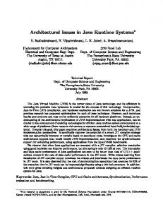
optical IP networks to high end quality of service virtual private networks running on ATM over SONET or WDM. It is conceivable that future Internet networks may be a seamless composite of a variety of transport protocols, each on their own dedicated wavelength. The following diagram illustrates a possible future network Internet architecture that integrates IP over WDM with ATM and SONET services. The IP over WDM might be used for high volume, best efforts computer to computer traffic, while IP over ATM might be used to support VPNs and mission critical IP networks while IP over SONET would be used to aggregate and deliver traditional IP network services that are delivered via T1s and DS3s . ATM/IP Network IP SONET Network ADM
ADM
IP/ATM Network OXC
IP SONET Network
HDWDM OC-3084
ADM OXC
ADM OXC
OADM OADM
IP Optical Network IP over ATM QoS & VPNs up to OC3
IP Sonet OC3, OC12, OC48
IP Optical Greater than OC-48
Figure 1.1 Integrated Optical Internet
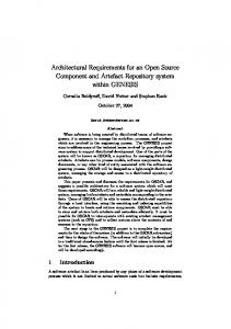
Currently carriers are deploying up to 16 wavelength, or "lambda" WDM systems. A number of manufacturer's have announced 32 and 96 wavelength systems and researchers in various laboratories are working on 200 and 1000 wavelength systems. In the next few years network bandwidth will dramatically increase as these very high density WDM systems are deployed. In fact it is quite likely that the growth of network bandwidth will far exceed the growth of computing power as stipulated by Moore's law. This will have a profound impact on the future architecture of future computer data networks, as the computer and not the network may be the controlling element for network design, quality of service and advanced network applications.
09/22/98 Copyright 1998, CANARIE Inc
5
1200 Bandwidth Doubling every 6 months
1000 800 600 400
CPU Power Doubling every 18 months
200 0 1995
2000
2005
2010
Figure 1.2 Growth of Bandwidth versus CPU
1.2 Why Build an Optical Internet? There is considerable debate in the telecommunications industry about the best technology for transporting IP services. Carriers are generally more committed to ATM as the common network technology. On the other hand there are many in the Internet community who believe that soon, just about everything will ride over IP and a network optimized to carry IP is the most appropriate direction. While there are compelling arguments for both sides of the debate the most likely outcome is that IP over ATM and optical IP services will exist in parallel to meet the spectrum of customer requirements for IP networking. This will be particularly true with the advent high density WDM systems which can support a multitude of transport service delivery mechanisms from traditional SONET/SDH services to the new optical ATM and IP architectures. The case therefore for an optical Internet essentially rests on the predicted volumes for Internet traffic growth and the expected predominant types of Internet applications. If Internet traffic continues to grow exponentially and for the bulk of traffic all that is required is a "best efforts" or an "ensured" delivery service then high volume IP pipes would seem to be the most appropriate technology. In additional to accommodating the huge anticipated capacity requirements of the Internet, an Optical Internet would be more efficient. As modern network overlays become increasingly survivable and robust, the fault tolerance built into the core transport network may becoming increasingly redundant, particularly for IP networks. Efficiencies and cost savings can be gained from single layer management of survivability. Fault tolerant features are largely inherent in IP. There is little doubt that there will always be a demand for network solutions that provide guaranteed qualities of service and well managed traffic engineering solutions, particularly for mission critical applications. If an IP network is capable of delivering such end to end service is a matter of debate and it is quite possible that ATM or other
09/22/98 Copyright 1998, CANARIE Inc
6
network technologies are best suited for that type of requirement. However, if the volume of "best efforts" or "ensured" IP traffic is the overwhelmingly predominant traffic type then it perhaps make sense to build a network that, first and foremost, can support that type of traffic. This does not mean that one network technology will displace another. The power of WDM is that both network solutions can be accommodated in a modern network infrastructure. With high density WDM neither the "bell heads" or the "net heads" are losers in the protocol wars. The winner is the customer in terms of increased choice in network offerings, services and cost savings.
1.3 Internet Traffic Growth Internet traffic volumes continue to grow exponentially. Current predictions indicate that data traffic principally made up of the Internet will exceed voice traffic in North America in the year 2001. 350 Data is 23x Voice Traffic
Relative Load
300 250 200
Data
150
Data is 5x Voice Traffic
100 50
Voice
0 1990
1995
Source:Lightwave April 1998
2000
2005
Year
Figure 1.3 Growth of Date Traffic versus Voice Traffic
A conservative estimate of Internet traffic growth is that it will double every 6 months. With this growth rate the aggregate bandwidth required for the Internet in the US will be about 35 Tbps (Terabits per second) by 2001-2002 [OLDY98]. As such a number of carriers are already planning to deploy OC-48 ATM and SONET/SDH networks for the sole purpose of delivering Internet data. With the advent of IP telephony, high speed connections to the home via cable modems or ADSL, fiber to the curb and the advanced applications that are being developed on Internet 2 and CA*net II there is every reason to believe that Internet traffic will continue on its exponential growth for the foreseeable future.
09/22/98 Copyright 1998, CANARIE Inc
7
Given this increasing demand for high bandwidth Internet in the coming years a large part of the debate has centered around the appropriate transport technology that will be used for delivering such bandwidth - ATM, SONET/SDH or WDM optical networks. The appropriate technology choice will be driven largely by the characteristics of future applications. Many people feel that interactive real time multimedia will be the driving application for high bandwidth networks. Such things as tele-immersive virtual reality, 3D interactive gaming, distance education and tele-medicine are cited as examples of the future applications that will drive the demand for increased bandwidth. If these do become the dominant IP applications then there is no question there will be requirement for large bandwidth networks. But in addition there are some early indications that existing data applications may grow significantly in size as well and will also drive the demand for large IP pipes.
1.4 Classification of Internet Applications and Data Types Applications on the Internet can be divided into three broad categories based on their unique traffic profiles and network requirements: human to human, human to computer and computer to computer applications. Human to human communications are considered to be those services where a live human being is required at both ends to complete the communications connection. Such applications include voice telephony and video conferencing, but also include the more futuristic applications such as tele-immersive virtual reality and Internet gaming. Human to human communications are the most demanding application of any network technology as the usual human I/O devices, the eyeball and the ear drum, have the limited buffering capability and hence are the least tolerant of delay and jitter in a communications channel. Most human to human communications are also sensitive to the speed of light delay in a network particularly those dependant on a high real time interactivity factor such as Internet gaming and tele-immersive virtual reality. However, when these applications mature in the next 15-20 years there will be an additional bandwidth explosion. Although major network upgrades will be needed to support voice and video on the Internet these services are in fact probably the slowest growing of all communication services. Traditional voice telephony has experienced very little growth in the past few years and video conferencing growth despite all its promises, remains anemic. And ultimately these applications are limited in growth by the number of human beings on the planet and their peculiar habit of requiring sleep approximately 8 hours (depending on life style) every day. Human to computer communications on the other hand has been the success story of the decade. Human to computer communications include the obvious things like the Web,
09/22/98 Copyright 1998, CANARIE Inc
8
but it also includes such things as voice and video playback services that are just starting to come on line. These applications can be delivered quite effectively over a "best efforts network" as long as there is sufficient buffering at the end points to smooth out the network induced jitter. There is every reason to believe that the exponential growth experienced by this type of communications connection particularly driven by the web should continue, if not accelerate over the coming years, Computer to computer communications may however, be the real driver for advanced networks and bandwidth. Computer to computer communication occurs when no human is required to initiate or terminate the communication. Such things as distributed web caching, multicast feeds, news feeds, batch processing, and database synchronization are typical of computer to computer communication. E-mail and voice mail are also considered to be computer to computer communications because they usually use a store and forward server and don't require relatively immediate connectivity across a network. A best efforts, high bandwidth IP network is generally all that is required to support most computer applications traffic. This type of traffic is in the early stages of growth. New applications being developed in the Next Generation Internet (NGI), Internet 2 and CA*net II programs in such areas distributed human genome sequencing, geo-spatial database mapping, astronomy imaging and database mining promise an even greater growth in this type of traffic. One of the fundamental assumptions for future advanced networks is that real time interactive human to human communications will be the predominant traffic type. Distance education, medical collaboration and tele-immersive virtual reality are cited as common examples of the future telecommunications traffic profile. However, if future networks turn out to be principally used for computer to computer and/or human to computer to communications then this will have a significant impact on the requirements for either a WDM or ATM networks as the network requirements for these applications can be generally best satisfied with a high bandwidth big pipe "best efforts" network.
1.5 Definition of Bandwidth One of the more confusing terms of reference between the traditional telecommunications versus data view of the world is the interpretation and definition of bandwidth. In high speed networks it is common to use the SONET/STM designations for bandwidth or capacity based on the OC-x (Optical Connection) or the international variation of STM-x. These designations for bandwidth are based on the assumption that all Tx/Rx circuits are full duplex balanced symmetrical so the bandwidth ascribed to these designations is for data transmission in one direction. They also do not include any protection bandwidth that may be associated with a given circuit.
09/22/98 Copyright 1998, CANARIE Inc
9
The data networking world evolved from definitions of bandwidth based on LAN technology. The first widespread LAN technology was based on the ethernet standard which was referred to as a half duplex "broadcast" medium where the Tx/Rx data shared the same link. The bandwidth given in "megabits per second" truly described the total available bandwidth in all directions. As wide area network data becomes increasingly asymmetrical and unbalanced it is important to distinguish the overall capacity of a network versus its nominal capacity as given by the more familiar OC-x or STM-x designations. As such we will try to endeavor to use the data definition of bandwidth throughout this document by stating the unidirectional bandwidth in Gbps. Table 1.0 illustrates the differences in network capacity assuming that both the protection and working fibers of a fiber ring are available for the transmission of data.
Designation
Nominal Bandwidth
Ethernet Equivalent Bandwidth
OC-48 OC-192 OC-768
2.4 Gbps 9.6 Gbps 38.4 Gbps
4.8 Gbps 19.2 Gbps 76.8 Gbps
Ethernet Equivalent using working and protection fiber 1:1 9.6 Gbps 38.4 Gbps 153.6 Gbps
Table 1.0 Ethernet Equivalents of Bandwidth on Fiber Systems In this document all bandwidth capacities describe the actual physical one way capacity of a given link. Hence a “nominal” OC-48 (2.4 Gbps) bi-directional link would be described as an aggregate bi-directional link capacity of 4.8 Gbps. This is important because in a future traffic engineered DWDM network the bi-directional link may be converted in 2 uni-directional wavelengths. Hence an accurate and common semantic for the underlying bandwidth capacity is critical to the design of future IP/DWDM networks.
09/22/98 Copyright 1998, CANARIE Inc
10
1 .0 Internet Traffic Characterizations The understanding of Internet traffic characterizations is crucial to the design of future networks. In the past there has been little work in this area, but thanks to recent developments at CAIDA (Cooperative Association for Internet Data Analysis http://www.caida.org) and the IETF IPPM WG ( Internet Protocol Performance Metrics http://www.advanced.org/csg-ippm/) tools and test suites are being developed that will allow network engineers fully understand the unique traffic profile of Internet networks. Early measurements and analysis by these groups point to some intriguing network characteristics that could have a profound effect on the design of Terabit Internet networks.
2.1 Fractal Nature of Internet Traffic There have been several studies [PAXS95] indicating that Internet traffic is fractal or self-similar in nature. Self similar means that traffic on Internet networks exhibits the same characteristics regardless of the number of simultaneous sessions on a given physical link. Traditionally in the telecommunications world traffic volumes aggregate with the number of users on any given link. There are a number of network traffic models [STUC85], based on well established queuing models for predicting traffic loads on voice telephony networks. The fundamental reason why traffic aggregation is well understood on voice networks is that voice traffic aggregates in 64 kbps steps with each phone call, and once a link is saturated no more callers are admitted to the network. However, on the Internet any single computer can use as much bandwidth that is available, and there is no limit on the number of computers that can access the network at any given time. In the event of congestion, all the computers back off and transmit less data until the congestion clears. This saturation and back off results in waves of data on most Internet links for which it is very difficult to predict or model. The consequences of this fractal nature of the Internet is that in order to minimize congestion IP networks must operate at a higher average peak to average load than in a traditional telecommunications network [COFF98]. A possible solution for network operators is to increase the buffer size at admission points into the network to smooth out the bumps and valleys. However, large buffering results in throughput delays of the data.
09/22/98 Copyright 1998, CANARIE Inc
11
1 user
Average Load
Average Load
100 users Need big buffers or big bandwidth to absorb peaks
Average Load Average Load
1 million users
Traditional Voice Traffic
Internet Traffic
Figure 2.1 Fractal Internet Traffic versus Poisson Voice Traffic
The Internet Performance and Practices Measurement (IPPM) Group have confirmed this fractal nature of the Internet via direct measurement [PAXS96]. Members of IPPM have installed devices called "Surveyors" at several network nodes throughout the US. These nodes collect data from a source node and time stamp the departure and arrival of the data with Global Positioning System (GPS) timers. The IPPM web site http://io.advanced.org/surveyor/support provides a real world example of the "self similar" nature of Internet traffic. As can be seen by these diagrams on that web site the bursty nature of Internet traffic means that even though a data link may have relatively low traffic volumes packet loss and delay can still occur. Conversely, on a heavily loaded link with severe packet loss there can be many instances of short periods of idle time.
2.2 Asymmetric Tx/Rx Data Another unusual characteristic of Internet data is the extreme imbalances that exist between the transmit and receive paths on most Internet links. This characteristic has been observed for some time on Canadian US Internet links where it is quite common 1:10 ratio between outbound traffic to the US and inbound traffic to Canada. The common explanation for this phenomenon is the large number of users who are pulling down web pages from US servers. This phenomena, however has also been observed on other international links and links within the US.
09/22/98 Copyright 1998, CANARIE Inc
12
The asymmetric data flows are attributed to larger server farms sending out large amounts of data in response to small requests and to the preponderance of users who download web pages. Web server farms tend to be clustered near large Internet service points while users are randomly distributed around the edges of the network. As a result near large interconnection points where web servers are located there is a large asymmetry in Tx/Rx data flows in favour of the Tx path exiting the servers. As the data is distributed to second tier regional networks and from there to local networks and eventually the end user the asymmetry proportionally increases to the receive side in the direction of the user retrieving the web data.
20:1 Cnet Regional Network 4:1
6:1
To Other Regionals
Backbone Network 3:1
2:1
Big Server e.g. Microsoft
Tx:Rx
Big Server e.g. Netscape
Figure 2.3 Examples of Asymmetric Data Flows on the Internet
It is presumed that web caching and mirroring will minimize the Tx/Rx asymmetry in the core of the network, but there will still remain large asymmetries that will vary throughout the day. Time zone changes introduce diurnal asymmetry as parts of the world are logging onto the Internet and accessing web servers on the opposite side of the planet. This diurnal shift in Internet Tx/Rx data is well illustrated by studies done by MCI Engineering on their commercial Internet links [MILL97] http://www.vbns.net/presentations/papers/index.html
The consequence of asymmetric is that considerable amount of Internet bandwidth, sometimes close to 50% sits idle, paradoxically at the same time as the bandwidth on the other side of a Tx/Rx pair is totally congested. This condition exists because the telecommunication systems of today are still designed to support primarily voice traffic. The diurnal asymmetry is amplified by the spatial
09/22/98 Copyright 1998, CANARIE Inc
13
asymmetry of Internet traffic, which is not present in voice network. Even with the latest WDM and SONET/SDH and ATM technologies most networks that are being deployed right now assume that voice will be the dominant traffic type.
2.3 Server Bound Congestion There is increasing evidence that traffic flow on the Internet is limited not by the network itself but by the servers providing data to requests from users. A recent analysis by Christian Huitema of Bellcore [HUIT98] indicates that over 50% of web congestion is due to server related issues. The server congestion is made up of 3 major components: the HTTP session initiation, the DNS lookup request and the actual system specific components such as CPU load, memory and I/O response of the server to the user requests. The HTTP session initiation involves opening the socket up on the server and other related activities. The DNS lookup request is the traditional process of resolving the web DNS name into an IP address. Typically on most Internet links a TCP congestion avoidance window is the controlling factor on Internet throughput [JACO88]. The server specified flow control window, in most cases, is larger than the TCP congestion avoidance window. Congestion avoidance in TCP sessions is a very complex subject and the reader is referred to the following web site for more detail http://www.psc.edu/networking/tcp.html The predominance of the congestion avoidance window being the controlling factor in most TCP sessions may actually, in many cases, be a flow control window bound session, but it is being masked by the silly window syndrome (SWS) in most TCP kernels. If the SWS were not present then there may even be a greater number of TCP sessions that are server bound then is being actually measured by Christian Huitema and others. In the presence of large bandwidth it is increasingly likely that the server flow control window will be the dominant control element in traffic throughput rather than today's congestion window. As a consequence with larger pipes, the Internet throughput will be increasingly server bound, even beyond the 52% server bound congestion experienced today. Unfortunately to the user the Internet will probably always appear largely congested. But there will be little that the network operator can do to obviate the situation except to install mirroring and caching. Undoubtedly servers will increase their flow control window size as they increase in CPU power. But will overall network capacity increase faster than the average CPU performance of most servers, particularly as the number of user connected to the Internet continues to grow unabated?
09/22/98 Copyright 1998, CANARIE Inc
14
This whole field of TCP flow control and congestion clearly needs more research to see if server bound congestion and flow control windows are indeed trending in the direction of being the dominant mechanisms for limiting throughput on Internet connections, particularly high bandwidth connections. If flow control windows which are symptomatic of server congestion dominate over congestion control windows on the Internet then this will have an major impact on network design and reliability. For example, in the event of a sudden drop in network capacity because of a fiber cut, or loss of a WDM channel, most users may not notice the disruption because their connection is server bound rather than network bound. The growing trend of server bound congestion may perhaps allow the use of protection fibers that currently site idle. The additional bandwidth can be used to absorb large fractal bursts, and in the event of a fiber cut, more traditional TCP congestion avoidance mechanisms would be the principal flow control mechanism to regulate access on the remaining working fiber. Ultimately this question of a server bound versus network bound will depend on the relative growth of bandwidth versus CPU power. If bandwidth growth principally due to the deployment of WDM is faster than Moore's law for CPU power and capacity then ultimately server congestion will be the controlling element in future networks.
09/22/98 Copyright 1998, CANARIE Inc
15
3.0 Transport Options - WDM, SONET/SDH or ATM This section compares optical WDM as a transport technology versus other Internet transport technologies such as ATM and SONET/SDH. ATM and SONET/SDH also have the capability of using WDM networks. This section discusses the pro's and con's of using IP over ATM over WDM and IP over SONET/SDH over WDM versus IP over WDM. The rate of change of technology also impacts a selection for core network technology. For instance, today’s implementation an IP network might included network elements embodying IP, Frame Relay, ATM, SONET/SDH, DWDM and finally different fiber types. The rate of change of technology is less as one moves from the IP to the fiber components of the network; for instance, the transport components lifetime (SONET/SDH, DWDM) is estimated at 10 years while the ATM component is less that five. If one chose to minimize network elements, for instance IP/DWDM, it may be more cost effective but there is more risk of obsolescence of investment. However this risk of obsolescence might lessen if IP becomes more embedded as the predominant traffic type.
3.1 Optical Internet versus Optical ATM Most carriers are strong supporters of ATM as a networking solution as they can aggregate different traffic types onto the same pipe and thereby enjoy significant savings in overall bandwidth as opposed to managing different services on different networks. Currently most carriers use completely different transport technologies for different services: Frame relay and ATM for data services, leased lines for private networks, SONET/SDH TDM for voice telephony and D1s for broadcast video. From their perspective it makes a lot of sense to integrate these services onto a single pipe and use ATM classes of service to deliver the differentiated services over the same pipe. One of the underlying assumptions of the carriers interest in ATM is that data services would be one of many competing services in a portfolio of service types. As such, ATM networks are optimized to carry a mix of different service types rather than being optimized for one specific service type. The other advantage of ATM in this environment is that it should be relatively easy to support Virtual Private Networks (VPNs) and classes of service for data. However, if current Internet trends continue, by 2002-2004 Internet data will be the overwhelming service type. In that scenario, it makes sense to build a network, first and foremost, that is optimized for the delivery of Internet data. The remaining services can then be delivered on top of an IP network (which may or may not be less than optimal) or continued to be delivered over a parallel ATM network.
09/22/98 Copyright 1998, CANARIE Inc
16
A network optimized for Internet delivery over ATM is not solely about the issue of framing or overhead as is currently debated in the network community. While the issues of ATM "cell tax" remains hotly debated between the "bell heads" and the "net heads" it is probably of insignificant consequence in high speed optical networks. The bigger issues are related to IP optical networking versus an optical ATM networking are more to packet Segmentation And Reassembly (SAR) in the routers, queuing delays, link layer complexity and routing network topology. ATM networks provide incredible degree of flexibility in term of network engineering and design. But this flexibility comes at a cost in terms of complexity. Running IP over ATM networks are in general much more complex to manage than traditional IP leased line networks. ATM however, does provide a powerful set of capabilities in terms of traffic engineering. Existing IP routing protocols have limited traffic engineering capabilities in terms of directing traffic across specific links principally because most the routing metrics are based on the number of routing hops. ATM circuits allow network engineers to establish "explicit" paths for different types of traffic and groom various links based on traffic load, congestion and so forth. MPLS promises to provide this same traffic engineering capability at the IP layer, but MPLS may end up introducing the same level of complexity as currently exists with ATM networks. One of the presumptions of the need for the development of the ATM protocol was that the design of the integrated circuits for variable cell-sized datagrams was too complex and too expensive. That presumption has been made obsolete by advances in integrated circuit technology, including greater speed, density, cheaper design using CAD tools, and protocol and architectural breakthroughs allowing ‘internalized’cell structure in terabit routers. It is now ATM boxes that have become expensive, as their added value is now less with the advent of high capacity routers and the development community is smaller. Because routers were initially software based it was felt that they would be incapable of keeping with higher data rates of today's modern networks. However, a number of companies are about to release routers that manufacturer's claim can route IP packets at wire speed up to 40 Gbps (nominal OC-768) per port. As such the need for fast ATM switches to do high speed routing is becoming less of an issue. The other major deterrent to ATM usage is the loss of bandwidth utilization due to SVC setup time. A SVC setup is orders of magnitude longer than the transit delay of a network. During the SVC setup time that data that is to be transmitted on the SVC has to be buffered until the SVC is setup. As such even if there was capacity in the network to carry the data immediately it cannot be transmitted until the SVC is established. With higher and higher bandwidths the SVC setup time can represent significant amounts of idle bandwidth to the point of being greater than the original volume of data that was to be sent in the first place.
09/22/98 Copyright 1998, CANARIE Inc
17
A number of techniques developed under MPOA using semi-permanent SVCs with VC merge has been proposed to compensate for this effective loss of bandwidth during SVC setup. In addition to the SVC setup time there is the TCP "slow start" mechanism which also can result in considerable effective bandwidth can being lost in the network by mapping TCP sessions or flows to relatively narrow band SVCs or PVCs. The TCP session will more likely remain in congestion avoidance mode in a narrow band VC rather than going to flow control mode if it were in an unencumbered broadband pipe. If all that ATM offers is increased complexity and no inherent improvement in throughput compared to the new class of Terabit routers, then the requirement for IP over ATM over WDM makes little sense particularly in large backbone networks. If the predominate traffic is IP, then the ATM network is an added level of complexity that is costly to network providers in terms of management.
3.2 Optical Internet versus SONET/SDH SONET/SDH OC-x channels look very much like WDM wavelengths to routers or switches as they are perceived to be a simple point to point link layer connections. However, this perceived simplicity from layer 3 masks a considerably complex switching architecture. The big advantage of SONET/SDH is its restoral capability in the event of a fiber cut or failure in a SONET/SDH node. A SONET/SDH ring network can switch to an alternate fiber, or to an alternate path on the other side of a fiber ring in the event of a fiber cut typically in less than 50 msec. This powerful restoral property of SONET/SDH is completely transparent to the IP networking layer. In an optical Internet, this sophisticated link management in the SONET/SDH layer may not be necessary. Protection and restoral capabilities are part of the Internet's intrinsic distributed survivability characteristic as envisaged by Kahn and Cerf [CERF74] As such, if the IP layer can shoulder the burden of survivability alone the requirement to have another layer of survivability underneath the Internet architecture may not be required. One of the original drivers SONET/SDH networks was the ‘synchronous’component, i.e. to make the entire network more synchronous and thus improve robustness. With current GPS technology, it is now reasonable cheap to drop in a high stratum clock at a network node, and also with the penetration of IP technology the network has become much more tolerant to timing faults. In this respect one need for intermediate layer of SONET has diminished. One of the big advantages of having a router directly connect to WDM wavelengths is that the router can use lambdas on both sides of a fiber ring and load share IP traffic and possibly double the bandwidth utilization of any Internet link at very low incremental cost to the carrier. In the event of a fiber cut it might be possible to throttle back "best
09/22/98 Copyright 1998, CANARIE Inc
18
efforts" IP traffic to be routed over the single surviving fiber, or alternatively re-routed over completely different path to the destination. Since Internet data is highly fractal or self similar in nature the consequences of a fiber cut or less severe in the data networking environment then it is in the traditional telecommunications environment. The loss of a fiber may also be compensated by well known techniques for flow control, buffering and or re-routing. In addition, an optical Internet the router can establish asymmetric transmit/receive lambdas to balance ingress and egress traffic across the network. SONET/SDH networks are always built under the assumption that transit/receive traffic is always in balance and as such cannot be optimized for asymmetric transmit and receive traffic flows.
3.3 WDM Switched Circuits vs WDM datagrams? In the optical research community there is a considerable amount of investigation into optical switching technology such as NxN optical switches. Most of this work is focused on micro-mirror technology and acoustic wave gratings. Unquestionably there will be need for some optical fiber switching for network configuration and protection switching, but this type of switching is not driven by actual data flows common to virtual circuits as is envisaged in future optical networks. This research is being driven by the fundamental tenant that telecommunication networks of the future will remain "circuit based". As such there is considerable work being done into network management of circuit switched optical networks which will use configurable OADMs, OCXs and NxN optical switches which can be used not only for traffic engineering purposed but dynamic data flows. One of the challenges of circuit based WDM is maintaining proper power levels and flat gain through an EDFA ( Erbrium Doped Fiber Amplifier) used in long haul WDM networks. If there is any sudden change in the power level from optical switching or wavelength translation device then the EDFAs can be thrown off kilter. The carriers spend considerable amount of time grooming and aligning optical links matching laser power with gain profiles of the EDFA across a multiple hop link. They can be understandably loath to see their network alignments change because of fluctuating power levels from optical switching or wavelength translation. Moreover, if the networks of the future are predominantly "datagram based" then there may not be a need for such complex switching technology. The router at the edge, rather than an optical switching device at the core, becomes the prime intelligent device for routing and switching packets between various optical links. As networks continue to increase in bandwidth the "circuit based" paradigm becomes increasingly inefficient of network resources. The setup time of a "circuit", as measured
09/22/98 Copyright 1998, CANARIE Inc
19
in terms of the bandwidth-delay, particularly an optical circuit will be many orders magnitude greater than size of the data segment in the first place. It is likely that for the foreseeable future, the setup time of an optical circuit across a large wide area network will be in the order of 100's of milli-seconds. On a single 10 Gbps (nominal OC-192) wavelength that setup time represents a lost network capacity of several Mbps of data. Many applications could have easily transmitted their data in that lost time it took to setup the network. This setup time and the complexity of managing circuits whether they be optically or ATM based may be the largest mitigating factors against a circuit based optical network.
3.4 Framing - SONET/SDH, Gigabit Ethernet, or Frame Relay Long haul WDM wavelengths require electrical regeneration approximately every 200500 km. The span distance is dependent on a number of factors including speed of modulation, type of fiber and so on. Most of today's telecommunication regeneration equipment is designed to work with SONET/SDH framing. If SONET/SDH regeneration and transponders are used in a network the IP packets from the routers have to be packed into SONET/SDH frames. SONET/SDH framing however suffers from several limitations. SONET/SDH framing is based on an 8 kHz voice synchronized time sample and the frame embeds header information within the payload. In addition IP packets can be mapped across two or more SONET/SDH frames or there can be many IP packets within one frame depending on the size of the IP packets. As a result, SAR processing of SONET/SDH frames can be very time consuming on a router interface card with a resultant degradation in throughput and performance. A number of companies are working on a new framing standard called "Fast-IP" or "Slim SONET/SDH" which will provide for much of the functionality of SONET/SDH framing but use more modern techniques in terms of header placement and matching frame size to packet size. One of the big advantages with SONET/SDH framing is that it carries signaling and network management information in its header bits. This network management information is important on long haul WDM systems, particularly where there maybe many electrical and optical repeaters. Being able to diagnose and locate a network fault quickly is very critical in a long haul network. However SONET/SDH has an large amount of overhead reserved for fault monitoring and operational support system. This overhead could be minimized if these functions were incorporated into the IP routing devices.
09/22/98 Copyright 1998, CANARIE Inc
20
The biggest disadvantage to SONET/SDH framing is the current high cost of SONET/SDH transponders and regeneration equipment. However, the costs are starting to drop with the advent of low cost SONET/SDH framing chip sets. Another option rather than using SONET/SDH regeneration is to use standard LAN equipment such as Gigabit Ethernet with transponders for signal regeneration. This approach works quite well in Municipal Area Optical Networks where bandwidth is more available and access systems can have proprietary protocols. On long haul systems where every bit must be squeezed out of available fibers is it is believed that it will work equally well on medium and possibly even long haul WDM systems. Gigabit Ethernet is not as efficient as SONET as it uses a simple block coding scheme where every 8 data bits are encapsulated in a 10 bit transmission block. This overhead results in an network inefficiency in excess of 25%. However, a number of vendors are working on a new “10 times” Gigabit Ethernet standard, specifically designed for DWDM systems. It is expected that the new 10xGigabit Ethernet standard will use a much more efficient block coding, perhaps even a synchronous coding like SONET. GigaBit ethernet does not have such a comprehensive suite of network status bits as SONET/SDH but its low cost and optimized design to carry the same frames that are used by most networked computers makes it an attractive alternative. The other issue that must be assessed with long haul Gigabit Ethernet is signal jitter and timing. Gigabit Ethernet is fundamentally an "asynchronous" protocol as opposed to SONET/SDH and therefore susceptible to timing and jitter problems. But computer to computer communications are extremely tolerant to timing variations and increase jitter. Given the cost of using Gigabit Ethernet is significantly less than traditional SONET/SDH regeneration equipment and as long as the jitter and timing can be managed without significant packet loss it makes for an attractive alternative. The other advantage of Gigabit Ethernet is that it uses the same frames that were originally generated by the hosts on either end of a connection. There is no re-mapping to other transport protocols like SONET/SDH or ATM and as such SAR (Segmentation And Reassembly) and bit stuffing operations are not required in the router interface to align the date frame with the transport frame. Gigabit Ethernet has another major advantage in providing for lower cost tributary delivery. In Figure 3.1 an example is shown of a small node that must be back hauled to a major node for connection to a backbone network. If SONET framing is used then expensive SONET tributary equipment, SONET routers and regen equipment is required to back haul the data to a major node. With Gigabit Ethernet on the other hand, the smaller node can be "bridged" with more traditional LAN bridging technology. In addition several small nodes can be bridged together on one common WDM channel. Gigabit ethernet currently operates at 1.25 Gbps. Hence a two way network with Tx/Rx would have an aggregate bandwidth of 2.5 Gbps. The Gigabit Ethernet working groups
09/22/98 Copyright 1998, CANARIE Inc
21
are also working on new 5 Gbps and 10 Gbps standards. An OC-48 WDM system can handle 1.25 Gbps and the new 10 Gbps Gigabit Ethernet may be used on OC-192 WDM systems.
$25K
$25K
G
G
G
G
$50K
G
Gigabit Ethernet Tributray with Bridged Switch
Gigabit Ethernet Tributray with Router
Gigabit Ethernet Regen With Gigabit Ethernet costs are much less and you can backhual bridged devices to and expensive high performance router
Gigabit Ethernet $250K
$125K $125k
$250K
SONET Regen
G
G Gigabit Switch
SONET Router Tributray
With SONET links everything must terminate on SONET gear - either routers or DCS
SONET
Figure 3.1 Gigabit Ethernet versus SONET
Avici Systems http://www.avici.com has also proposed the use of Frame Relay protocol as a framing and link protocol on high speed networks. This concept has yet to be proven in a working network environment.
09/22/98 Copyright 1998, CANARIE Inc
22
4.0 Fundamentals of Optical Networking This section gives a brief overview of some of the design constraints that optical technology imposes on Internet design. For a more in depth overview of optical networking the reader is referred to the following textbook [RAMA98] Also there is an excellent tutorial paper on the Lightwave web site http://www.broadbandguide.com/lw/reports/report02983.html
4.1 Fiber Types There are essentially 3 types of single mode optical fibers which are characterized by their primary spectral window 850 nm, 1310 nm and 1550 nm respectively. For long haul networks 1550 nm fiber is the most common as the EDFAs ( Erbium fiber Doped Amplifiers) operate in small part of the 1550nm operating window. This means that long sections of 1550nm fiber, up to 500 km can be deployed without electrical amplification. There are no similar optical amplifier technology for the 1310nm and 850nm fiber systems. As such these fibers are usually deployed in metropolitan or campus environments where no optical amplification is required or where electrical amplification is relatively inexpensive. There are three types of 1550 nm fiber - No dispersion shifted fiber (NDSF), dispersion shifted fiber (DSF), non-zero dispersion shifted fiber (NZDSF) or lambda-shifted fiber. NZDSF is now the preferred alternative for systems expecting to deploy WDM. Before the advent of WDM most carriers deployed NDSF, which has the largest installed base, or more recently dispersion shifted 1550 nm fiber which was manufactured to have the minimum amount of chromatic and polarization dispersion at the desired transmission wavelength. These fibers were intended for Time Division Multiplexing transmission schemes and at one time it was thought that this would be the primary mode of data transmission over optical fiber. But it became increasingly evident that the higher the speed of TDM transmission networks incurred more non-linear effects such as chromatic dispersion, polarization dispersion and so on. The common convention is that 10 Gbps (nominal OC-192) is the upper limit of TDM transmission on an optical fiber or at most 40 Gbps (nominal OC-768). At any rate, the orders of magnitude increase in capacity by WDM easily eclipse advance expected for TDM on embedded fiber plant. With the advent of WDM fiber manufacturers discovered that optimizing for a single wavelength had a negative effect on WDM transmission particularly on those wavelengths outside of the center wavelength. Due to chromatic dispersion in the fiber signals get deformed because of propagation velocity difference between wavelengths. Hence many newer optical fibers have a non-zero dispersion profile to provide more consistent chromatic dispersion across the various WDM wavelengths.
09/22/98 Copyright 1998, CANARIE Inc
23
Today there are commercial WDM fiber systems available delivering bit rates in the range of 40 to 80 Gbps by combining a large number of 2 Gbps (nominal OC-48) or 10 Gbps (nominal OC-192) wavelengths. Typically there is a trade off between the individual capacity of each wavelength and the number of wavelengths so the overall capacity of the fiber is generally unchanged regardless of whether each individual wavelength is signalled at 10 Gbps (OC-192) or 2 Gbps (OC-48) data rates. 10 Gbps (nominal OC-192) wavelengths generally require wider spectral spacing then 2 Gbps (OC-48) systems. However, the big drawback to higher data rates on individual wavelengths is the need for closer optical repeater spacing. Fiber dispersion has a significant impact on the spacing and number of optical amplifiers and electrical regenerators. Fiber systems today typically have dispersion values that require optical amplifiers or EDFAs every 250 km. In the past year eeveral fiber manufacturers have announced fiber that has significantly improved dispersion characteristics. These new fiber products, combined with narrow spectral laser and dispersion correcting devices allow the deployment of fiber systems up to 10,000 km with no electrical regeneration.
4.2 Lasers One of the big cost factors in WDM systems is the high performance lasers required for each individual wavelength. These lasers have to be extremely stable and operate in a very narrow spectrum. As the lasers can be located in small unheated repeater huts they must also exhibit strong temperature stability as well. Generally each laser is coupled with an external modulator and an optical filter that removes any extraneous signal outside of the given wavelength. These optical filters must also be of manufactured to extreme tolerances.
4.3 EDFAs To overcome the attenuation in the fiber, amplifiers are required. Only a few years ago electrical amplification was the only technology available. However optical amplification using special doped sections of fiber called Erbium Doped fiber Amplifier (EDFA) is now quite common on long haul systems. They provide amplification in the 1550nm transmission window typically over a 20 nm bandwidth. Most EDFAs deployed today are "broadband" amplifiers in that they amplify all the wavelengths in a WDM as a group rather than amplifying each wavelength individually. However a separate amplifier is required for the Tx wavelengths and the Rx wavelengths. As most EDFAs are broadband amplifiers special precautions are needed in order to have a flat gain profile over the entire WDM bandwidth. A non-flat profile gets accentuated by
09/22/98 Copyright 1998, CANARIE Inc
24
an amplifier cascade and cannot guarantee successful transmission of a WDM signal. As a result electrical amplification is required after about a half dozen optical amplifiers. As a rule of thumb most current lasers can drive a signal about 80 km without optical amplification at 2 Gbps (nominal OC-48) speeds and 50 km at 10 Gbps (OC-192) speeds. So most municipal area WDM networks generally do not require amplification of any type. Current WDM long haul systems can support up to 5 or 6 cascaded optical amplifiers before electrical amplification is required. This results in optical spans of up to 400 km at OC-48 speeds and 250 km at OC-192 speeds. These numbers are only approximate averages as network engineers can vary repeater spacing with a combination of more powerful lasers and the use of passive dispersion correcting devices. Link loss budgets vary considerably for different fiber types
4.4 Optical Couplers To ungroup or group individual wavelength signals in or out of a WDM signal a passive device optical coupler is used. An optical coupler will demultiplex or multiplex all the wavelengths in a WDM system. As the signal is split passively, insertion loss in the optical coupler must be also taken into account in calculating the span distance of optical systems. Most optical coupler are usually integrated with a pre or post optical amp to compensate for insertion loss in the coupler itself. Each manufacturer of optical equipment has a different approach to handling transmit/ receive wavelengths. Some optical equipment manufacturers separate the transmit and receive wavelengths onto physically separate fibers, whiles other use different wavelength "bands" within the same optical fiber.
4.5 Electrical Repeaters Electrical repeaters are still required in long haul WDM systems. Impairments caused by cascaded EDFAs such as spontaneous noise accumulation become too large to be corrected optically after the signal travels through 5 or 6 such amplifiers. Electrical regeneration is defined in three levels - 1R, 2R, and 3R. 1R "fully transparent" regeneration simply takes any input signal and amplifies it. An example is the EDFA. 2R "digitally transparent" regeneration converts the optical signal to electrical, reshapes the pulse, converts back to optical and amplifies it. Transponders which can accept input signals of any non-SONET protocol are examples of 2R regenerators. 3R "SONET" regeneration adds retiming to the process to eliminate jitter.
09/22/98 Copyright 1998, CANARIE Inc
25
Most electrical repeaters in SONET/SDH WDM systems must do R3 regeneration. As the practical upper limit of electronic regeneration is 40 Gbps this is thought to be the upper throughput limit of most WDM systems. As lower dispersion fiber becomes more common and soliton technology is deployed this electrical amplification limitation will eventually disappear in the next few years. Some equipment manufacturers electrical amplify and regenerate all the wavelengths as a group while others do the electrical regeneration on a wavelength by wavelength basis. As a major cost of a WDM system can be the electrical regenerators that are required every 200 - 500 km significant savings can be made by deploying asymmetric Tx/Rx wavelengths. The optical wavelength capacity may be still present in the system, but given wavelengths in a transmit or receive group may not be electrically amplified at each node along a long haul WDM system if only one side of the electrical amplifier is deployed. As most long haul WDM systems currently deployed are designed to support almost exclusively SONET/SDH networks the electrical regeneration equipment is designed to regenerate SONET/SDH frames. For this reason SONET/SDH framing will be required on these networks for the forseeable future regardless of whether the upper layer network is a SONET/SDH, ATM or IP network. However with the advent of Gigabit Ethernet WDM systems a more cost effective electrical regeneration can be done with off the shelf GigaBit Ethernet switches connected to transponders that do 2R regeneration to shape the laser output before being injected into the WDM coupler.
4.6 Transponders Transponders are devices that convert the optical signal from a router or other device and produce an optical signal at the correct ITU wavelength to be inserted into an optical coupler. The transponder in its simplest form, can be a wavelength converter only and can perform conversion strictly in the optical domain using optical gating or wave-mixing techniques with no regeneration or opto/electrical conversions. Some transponders are data transparent and are ideal for WDM Gigabit Ethernet networks. More expensive transponders, used in SONET/SDH networks re-shape and retime the incoming data from the router to match the transmission speed of the WDM network. The transponder also serves as a demarcation device, ensuring network integrity by providing ‘keep alive’signal and test capabilities. Back to back SONET/SDH transponders are sometimes used as an electrical repeater in most long haul WDM systems.
09/22/98 Copyright 1998, CANARIE Inc
26
4.7 Optical Add Drop Mux, Cross Connects and Switches These devices are generally not widely used in long haul WDM systems. However they are starting to be deployed in a number of municipal area WDM systems where optical and electrical amplifiers are not required. Optical Add Drop Muxs will selectively drop or add a specific wavelength on a WDM fiber. Rather than demuxing all of the wavelengths through an optical coupler common in a long haul system only a given wavelength is added or dropped at a node. The other wavelengths are passed through the node optically. An optical cross connect is in essence two optical add drop muxs connected back to back so that a wavelength from one WDM system can be inserted into another separate WDM system. Today most optical add drop muxs and cross connects are passive devices that must be pre-configured to drop or add specific wavelengths at a node. However, NxN optical switches are now starting to appear commercially which will allow for dynamic configuration of optical add drop muxs and cross connects. Optical switches use tiny mechanical mirrors or acoustic surface wave filters to do the actual switching. These devices are quite slow and it is unrealistic to expect that they would ever be capable of working at data switching speeds. True optical switching and routing wire line speeds will probably not happen for a few years yet. Municipal Area WDM systems is where most of this optical technology is deployed. On long haul WDM systems all the wavelengths have to be electrically re-amplified, in any event, at most major nodes and so all the switching and routing is done at the electrical level rather than at the optical level.
4.8 WDM standards and interoperability Most modern WDM systems space their wavelengths on what is commonly referred to as the ITU grid. The ITU grid specifies the minimum spacing and the actual "wave length" of the individual wavelengths in a WDM system. This is the first step towards an interoperable standard for WDM transmission systems. But even though most systems now conform to the ITU grid spacing there is no standard on bi-directionality, wavelength grouping, spacing, power levels, polarization, etc. As such it is expected it will be some time before there will be true interoperability between WDM systems from different manufacturers. This also makes it difficult, if not impossible, to deploy wavelength routing, for example, between a regional network whose equipment is from one manufacturer to a backbone network provisioned by another manufacturer.
09/22/98 Copyright 1998, CANARIE Inc
27
5.0 Possible Optical Internet architectures This section describes a number of potential Municipal Area Network (MAN) and Wide Area Network (WAN) optical Internet architectures.
5.1 Basic Architecture of an Optical Internet Figure 5.1 illustrates some of the basic architectural concepts of an optical Internet as defined in this document. The principal defining feature is the use of high density Wave Division Multiplexing fiber to deliver individual wavelengths directly to high performance IP routers. The wavelengths are coupled and de-coupled from the fiber using a WDM Coupler or sometimes referred to as optical multiplexer and/or an optical add drop multiplexer. The WDM coupler is a passive device that using the same principle of a prism splits or combines the light beam into its constituent wavelengths. The output and input of the WDM coupler are simple fiber connectors which then direct the data on the original wavelength to either the traditional SONET gear or the high performance IP router. Both sides of ring used for IP traffic Traditional SONET Mux or DCS
Traditional SONET Mux or DCS WDM
WDM 3 0C-48 Tx 2 OC-48 Rx
Asymmetric Tx/Rx lambdas that can be dynamically altered
Traditional SONET Restoral Low priority traffic that can be buffered or have packet loss in case of fiber cut
Figure 5.1 Architectural Features of an Optical Internet
09/22/98 Copyright 1998, CANARIE Inc
28
One of the significant advantages of directly coupling the router to individual wavelengths is that the optical system can be traffic engineered to closely match the traffic profile of the Internet data. As noted in section 2.2 Internet data can be highly asymmetric between the transmit and receive channels. Existing telecommunications systems cannot take advantage of this asymmetry as they were originally designed for symmetric voice traffic. In the example shown in Figure 5.1 there are a total of 9 wavelengths, 5 on the working fiber and 4 on the protection fiber. Two of the wavelengths are being used for traditional SONET services on the working fiber with 2 wavelengths, unused and held in reserve on the protection fiber in case of a fiber cut. There are 2 Tx and 1 Rx wavelength on the working fiber and one Tx and one Rx wavelength for a total of 3 wavelengths going from right to left and 2 wavelengths going in the opposite direction. This type of configuration would support a 3:2 Tx/Rx data asymmetry which is relatively common on the Internet today. The other major distinguishing feature of an optical Internet is the use of both sides of a fiber ring, if it is available. By doing restoral at the IP layer rather than at the physical layer at lot more sophisticated restoral techniques can be used as compared to the traditional SONET restoral. It is conceivable that given the extreme burstiness of Internet data that the average traffic load on such a network could be significantly less than half of the aggregate bandwidth of both the working and protection fibers. Rather than handling bursts through buffering, or worse via packet loss as is common in today's Internet the idle bandwidth in the protection fiber can be put to good use to absorb bursts without inducing jitter, delay or packet loss. In the event of a fiber cut traditional buffering and packet loss techniques can be used to flow control the data volume through the remaining working fiber. As well, in the event of a fiber cut, traffic such as IP telephony that is sensitive to jitter and delay can be given a higher priority over the best efforts IP traffic using established and well know IP prioritization techniques. The detection of a fiber cut and instigating restoral procedures at layer 3 still remains an area of considerable research. A number of technologies and protocols have been proposed, but they are as yet untested or proven on real world networks. The other advantage of using the working and protection fiber is the ability to deploy "cut through" or "by-pass" wavelengths as shown in Figure 5.2. In comparison to ATM or IP "cut through" techniques there absolutely no latency due to buffering in switches or routers. The disadvantage of optical cut through is that it is not dynamic and has to preengineered. A number of companies are developing optical cross connect switches to allow faster bypass switching, but the switching speed will remain very slow compared to traditional routing and switching cut through techniques. The use of optical switching to
09/22/98 Copyright 1998, CANARIE Inc
29
support cut through of data flows of a few megabytes is unlikely in the forseeable future. Given the bandwidth delay product of optical switching it is hard to imagine that it will ever be used for data flows, but rather its most likely application is to allow relative "real time" traffic engineering of wavelengths to support diurnal and other long lived large aggregate traffic.
Traditional Hop by Hop Routing
US Gateway
Toronto
Montreal
Working Fiber
Calgary
Vancouver
Protection Fiber By pass WDM Figure 5.2 WDM Bypass or Cut through
In Figure 5.2 note again the use of asymmetric wavelengths on the protection fiber. In this example the bulk of the data flow is assumed to come from the US Gateway to the various Canadian cities. The Toronto router is the only router that has a path to the US on the working fiber. Figure 5.3 shows what a typical node might look like on a carrier fiber network. This node supports the carrier's traditional SONET TDM services as well as the optical Internet. Two routers are used for redundancy. One router faces the protection fiber and terminates the unidirectional data links that are used for the "bypass" or " cut through" wavelengths. The other router is used for traditional hop by hop routing and provides tributary services to local customers. Note the requirement for a transponder on each output port of the router. The transponder converts and shapes the optical output of the router so that it can be launched into the WDM coupler. In time, it most likely that the optical outputs of the routers themselves will be able to be directly coupled into the optical coupler.
09/22/98 Copyright 1998, CANARIE Inc
30
Carrier Tributary SONET services - OC3c, OC12c, etc WDM Coupler
WDM Coupler
DCS TransportNode Traditional SONET
OC-48/192 Working Fiber
Working Fiber
To Local GigaPOP (ATM, SONET, WDM etc)
To Local GigaPOP (ATM, SONET, WDM, (etc) Carrier Router
Transponders WDM Coupler
WDM Coupler OC-48/192 Protection Fiber
Electrical Regenerator Cut thru asymmetric Lambdas to next Router
Protection Fiber
Figure 5.3 Typical Optical Internet Node
5.2 WAN versus MAN optical Internet networks Municipal Area optical networks are where leading edge optical Internet technology is most likely to be first deployed. Municipal Area WDM systems can have fibers dedicated to one specific use and the wavelength don't necessarily have to be shared amongst different user groups with different objectives. As such, in a MAN WDM system, it is relatively easy to dedicate a single WDM wavelength for "crash and burn" testing while another WDM wavelength can simultaneously be used to support production traffic. It is in MAN WDM systems where we will probably see the first deployment of novel photonic architectures using such things as optical switching, wavelength translation, wavelength routing and so on. Given the costs of optical amplifiers and electrical repeaters on long haul WDM systems it is only practical that an optical Internet share wavelengths with other production or commercial users. As the EDFAs on long haul WDM systems are extremely sensitive to signal disruption typical of that caused by optical switching or wavelength routing it is unlikely that the carriers would tolerate such disruptions to their networks.
09/22/98 Copyright 1998, CANARIE Inc
31
In long haul WDM systems therefore the individual wavelengths will only be accessible through an electrical interface under the control of the carrier such as a transponder. This means that switching and routing will be done at the electrical level before the aggregated signal is inserted into the WDM system. The WDM wavelengths in fact looks like a layer 2 point to point connection between the respective routers and/or switches. Consequently the architecture and design issues of a long haul WDM optical Internet are very similar to those of a network using ATM PVCs or leased lines. However there are some advantages of directly coupling routers to the WDM wavelengths rather than going through one or more intermediate layers such as the TDM or ATM layer. Routers that are directly coupled to the WDM wavelength will have direct control over that traffic that goes on the wavelengths over both the working and protection fibers in long haul fiber rings. This means between any two routers there are, in effect 2 parallel paths. Further given the Tx/Rx asymmetry of most Internet links the WDM wavelengths on some supplier's optical equipment can be configured such that there are different ratios of Tx/Rx wavelengths on any given link. For further discussion on the necessity of why long haul WDM systems will have to remain "opaque" and use electrical interfaces rather than transparent optical wavelength routing please refer to the following Lightwave article http://www.broadbandguide.com/lw/feat/feat2982.html
In the MAN it is relatively easy to deploy an optically transparent network as there is no need for electrical regeneration. Given the short segment between nodes it is possible to deploy a LAN based protocol network such as Gigabit Ethernet.
5.3 Hybrid Optical Internet Networks Given the high cost of long haul WDM systems in some cases it may make more sense to deploy hybrid optical internet networks until traffic volumes justify a full optical architecture. One example would be to use an optical link for a high volume transmit traffic and the lower volume receive traffic would use an ATM PVC or SONET/SDH OC-x circuit. Alternatively the WDM wavelengths can be used for high volume data transfer between central nodes and ATM PVC's or SONET/SDH OC-x's are used for restoral purposes in the event of a fiber cut. Figure 5.4 illustrates a hybrid optical Internet. The architecture assumes a high Tx/Rx asymmetry in the traffic flows where all the optical wavelengths are used to carry traffic in one direction. The return traffic is carried on ATM PVCs. As well hop by hop connectivity is done at the ATM layer.
09/22/98 Copyright 1998, CANARIE Inc
32
Working side of fiber ring used for IP traffic Traditional SONET Gear
ATM network used as a return path to optical IP forward path
Asymmetric Wavelengths SONET
OADM
OADM
SONET
Traditional SONET Restoral
Large Traffic Flows in this direction
Figure 5.4 Hybrid Optical Internet
This type of architecture may require the use of the Unidiectional Link Layer Routing protocol (UDLR) [DABB96]. UDLR has been a proven approach to network routing in a number of unidirectional overseas Internet satellite links. Another possibility as described in section 6.0 is the the use of MPLS Uni-directional Traffic trunks [AWDU98].
Working side of 4/BLSR 1:1 span ring used for IP traffic Traditional SONET Gear
ATM network used as a backup path to primary IP path in case of network failure
SONET
OADM
OADM
SONET
Traditional SONET Restoral
Figure 5.5 Hybrid ATM and Optical Internet - ATM link used for backup
09/22/98 Copyright 1998, CANARIE Inc
33
Figure 5.5 illustrates a hybrid optical network architecture where the restoral path is a conventional ATM network. This type of architecture is possible, even with the lower bandwidth capability of the ATM network. As described in section 2.1, Internet data is extremely fractal and bursty. So even though peak bandwidth may be very high, the average bandwidth can be significantly less than the peak bandwidth. In the event of a fiber cut, such that the ATM circuit is used for restoral purposes, the data peaks will have to be significantly buffered to be carried on the ATM network. If the Internet traffic is predominantly best efforts computer to computer traffic the effect on the end stations would be a microsecond delay in the data transfer which can easily be accommodate by the end stations if they are computers. If the traffic is human to human traffic, then it would have to be prioritized in the buffers so as to minimize jitter and delay. Clearly another important issue is the speed of the restoral capability via the backup ATM circuit. Much work has yet to be done on layer 3 restoral protocols as further described in section 6.0 A third hybrid optical architecture is to treat the WDM channels as one way broadcast similar to the delivery of Internet data by satellite.
ATM Cloud for regular IP and QoS
US Gateway
Toronto
Montreal
Calgary
Vancouver
WDM used to carry bulk high volume traffic in one direction Figure 5.6 WDM Broadcast
This type of architecture is commonly used on overseas links where a satellite circuit is used to augment the one way bandwidth between the overseas destination and the US where most web traffic originates.
09/22/98 Copyright 1998, CANARIE Inc
34
In theory it might be possible to deploy optical multicast devices at each node and use only one wavelength for the distribution of the data. However, this may be impractical of the bulk of the data is made up of individual TCP flows.
5.4 Using both sides of a fiber ring As mentioned previously one of the major attractions of connected WDM wavelengths to a router is the ability to use both sides of a fiber ring used in long haul WDM systems to give the route access to all of the bandwidth and eliminate network elements. By using both sides of a fiber ring, large data bursts can be transmitted without buffering or packet loss. This minimizes jitter and delay in the network and the need for complex QoS mechanisms to prioritize traffic. Even though the working path and the protection path may be available in terms of bandwidth, the average load should be kept at less than half of the aggregate bandwidth so that in case of a fiber cut, there will still be sufficient bandwidth to handle the offered traffic. In that case, packet loss will occur on bursts and the TCP congestion avoidance mechanisms will throttle back the data rate on any given flow. The IP datagram concept is premised on a survivable re-configurable network architecture using various routing algorithms. The challenge is that this network survivability was not designed to work a microsecond speeds typical of a SONET network. However there are a number of promising architecture possibilities that might be able to provide the same speed of protection speed at layer 3 as further described in section 6. The carriers commonly deploy WDM networks in ring topologies. Point to point fiber connections are used only in access links to hubs or nodes or municipal or long haul networks. There are basically two types of WDM rings. The ring topology is driven by the overlay SONET architecture more commonly described as UPSR (Unidirectional Path Switched Ring) and BLSR (Bi-directional Line Switched Ring). BLSR rings come in 2 flavours 2/BLSR and 4/BLSR, the former necessitates a SONET network layer while the later an be adopted to other network protocols [RAMA98]. UPSR rings are usually deployed in metropolitan areas and are referred to as 1+1 protection switching. UPSR rings were deployed in older fiber systems with no WDM capability. In 1+1 protection switching traffic is simultaneously transmitted on two separate fibers (or wavelengths) from the source to the destination. The destination selects one of the
09/22/98 Copyright 1998, CANARIE Inc
35
two paths for reception of the data. If there is a fiber cut the destination switches to the other path. This type of protection is very fast and requires no signaling protocol on the other end. The big draw back with UPSR is that there is no path or bandwidth re-use. The bandwidth of the ring must equal the total of the ingress bandwidth of all the nodes attached to the ring. As both the working and protection paths are used to carry data, UPSR 1+1 ring architecture is generally not applicable to an IP router network. The routers in an IP router network keep track of the routing topology and route packets accordingly. In the event of a fiber cut routing tables must be updated to reflect the new network topology. An optical IP network using a UPSR architecture is therefore not likely to have the same response time as an equivalent SONET UPSR ring to a fiber cut. Moreover as the fiber must be used in both directions, trunk combining or QoS prioritization techniques cannot be used. In the case of UPSR fiber rings the best solution for redundancy and path protection is to use the SONET layer. The tradeoff is loss of bandwidth. Generally UPSR architectures are losing favour to BLSR architectures principally because of the bandwidth re-use factor and the added protection provided by BLSR architectures. However, a number of vendors offer UPSR emulation on BLSR rings because of the very high speed protection capability offered by UPSR. For that reason, UPSR architecture might be advantageous in an optical IP network particularly if the routers can operate directly as SONET ADMs (Add Drop Multiplexers). BLSR architectures use a switched protection path, commonly referred to as 1:1 or 1:N protection switching. In 1:1 rings there is a one to one correspondence between the working and the protection path. In 1:N systems there is one protection path for "N" working paths. Clearly 1:N protection paths cannot be used for optical Internet as they are reserved for protection several paths which may support different types of services. There are two ways of simultaneously using the working and protection paths on a 1:1 fiber or wavelength ring. The first is to place a " combiner" or "inverse mux" in front of the router to combine the bandwidth of the 2 fiber paths into one bandwidth pipe into the router. This technique of inverse muxing is used quite commonly to multiplex several low speed links into one combined high speed link. A combiner or inverse mux may be effective on 4/BLSR fiber rings to link together the intermediate spans to appear as single pipes to the router.
09/22/98 Copyright 1998, CANARIE Inc
36
Several equipment manufacturers have developed technology that works as a link layer combiner or inverse mux to deliver a layer 3 seamless high bandwidth pipe. To the router, the effect of a fiber cut is to reduce the effective bandwidth by half. However, to throttle back the data flow if it is greater than the working aggregate bandwidth of the working fiber requires the invocation usual TCP congestion mechanisms on each flow to be activated. This may take several seconds on high bandwidth link. The other approach to using both sides of a fiber ring is to terminate both sides on one or more separate routers, or router ports and use more traditional routing protocols such as OSPF and IS-IS to manage the dual path. The challenge in this architecture is to load balancing with a routing protocol that only does binary route selection. MPLS and other IP switching protocols, however, may be better suited for this type of application as discussed in section 6.
5.5 Optical IP Municipal Area Network A number of companies have announced municipal area WDM network products. These products can support up to 64 WDM channels up to 80 km without a repeater. As no repeaters are required, in most cases they provide for complete data transparency and used to deliver analog signals such as video, as well as data on the individual wavelengths. As mentioned in section 5, data transparency is still not possible on long haul networks which requires electrical regenerators. So for the forseeable future the interface to the backbone network will be through an electrical router or switch. However, optical switching and cross connects are possible on regional optical networks as there can be complete data transparency on each link.
09/22/98 Copyright 1998, CANARIE Inc
37
Figure 5.7 illustrates a typical municipal WDM IP network that interconnects to a backbone optical IP network. In this example, a Gigabit Ethernet wavelength is used to interconnect the optical backbone network with the GigaPOP router. Similarly a Packet over SONET wavelength is used to connect the same router to a commercial Internet router. Along the same fiber, other wavelengths are used to provide point to point connections between local universities and the GigaPOP. In addition another wavelength is being used to distribute analog video from one campus to another.
Central Office
To Commercial Internet
To CA*net 3
Packet over SONET
GigaBitEthernet OADM OXC?
ATM OADM
Local WDM Fiber Ring Provided by Cable Company or Telco
Ethernet
University A Router
OADM
Reuse of same wavelength Analog Video
OADM GigaPOP Router
Figure 5.7 Municipal Optical IP Network
A 64 channel WDM fiber can provide approximately 150 point to point connections depending on how many wavelengths can be re-used. Each one of these channels can support a dedicated Gigabit Ethernet or an OC-48 connection. One of the big advantages of an municipal optical Internet is the low cost of delivery such a service. The traditional spoke and hub architecture of traditional urban network architecture with low bandwidth links into a major central switch is not necessary. In effect the WDM fiber extends the office LAN concept into a much larger geographical setting. The costs of delivering Internet services over such an architecture may prove to be significantly less than traditional loop technologies.
09/22/98 Copyright 1998, CANARIE Inc
38
5.5 Optical Internet Exchange Another variant of the municipal optical Internet is the Optical Internet Exchange. Currently Internet exchange points are based either IP or ATM switches. Most IP switch exchange points are badly congested and suffer from head of line blocking problems through the switch. The more recent ATM exchange points have higher capacities and suffer less from congestion. The other main attraction of an ATM exchange is that Internet Service Providers can keep their routers and other equipment on their own premise and only have individual point to point virtual circuits transit the switch. Some Internet Exchanges are also large hosting sites for high performance web servers such as the Digital Internet Exchange in Palo Alto. ISP B Web Server
Packet over SONET
OADM
Ethernet
ISP A
ATM OADM
OADM
OADM Common Internet Exchange Router
Figure 5.8 Optical Internet Exchange
An Optical Internet Exchange has all the advantages of an ATM exchange without the need of a central ATM switch. Figure 5.8 gives an example of how an optical Internet exchange might be configured. A municipal fiber ring would be deployed between various distributed facilities that hosted the routers and switches of a number of independent ISPs. ISPs could establish point to point wavelengths between their routers and or ATM switches.
09/22/98 Copyright 1998, CANARIE Inc
39
It is quite common to have highly asymmetric traffic flows across an exchange, particularly from those that host large web servers. One wavelength would be dedicated to for the high volume asymmetric data flow, while a shared wavelength could be used for lower volume return traffic which might also be routed through an a more traditional exchange router facility. The exchange router facility with a set of common wavelength for all ISPs can also be used for low flow traffic volumes that do not need their own dedicated point to point wavelengths.
ISP B Web Farm
ISP C ISP A
Common Internet Exchange Router Small ISPs Figure 5.9 Logical Diagram for Optical Internet Exchange
09/22/98 Copyright 1998, CANARIE Inc
40
6.0 Traffic Engineering, Restoral, QoS and Network Management Probably the largest area of research that has to be undertaken with optical Internets is in the area of traffic engineering, network management, quality of service and network restoral. This section describes some of the major issues in these areas and some possible solutions.
6.1 Traffic Engineering Traffic engineering is concerned with the performance optimization of network resources to effectively match the high cost of network assets with the ever changing demands in bandwidth and quality of service [AWDU98] Internet routing protocols are generally not well suited to traffic engineering of a network. As such network engineers have relied lower layer transport clouds, particularly ATM networks. The use of lower layer transport networks enables virtual topologies that appear as physical links to the IP layer. ATM networks in particular provide for a rich set of constraint based routing, call admission control, traffic shaping and policing resources. In an optical Internet there is no lower layer transport protocol, and as such traffic engineering must be done at the IP layer. There have a number of proposed solutions for performing traffic management at the IP layer, but the most promising appears to be MPLS - Multi Protocol Label Switching [CALL98]. MPLS integrates a simple fixed label switched networks with a more complex network routing protocol. Throughout the interior of a cloud the labels are used to make simple one hop forwarding decisions. This simple construct allows for some very sophisticated network engineering management and traffic engineering capabilities at the IP layer.
6.2 Restoral Issues In traditional telecommunication networks restoral and protection has always been considered a layer 1 function and generally transparent to upper layer services. SONET/SDH, as well as the recent introduction of optical ADMs or switches, is a well established technology built exactly for this purpose. In the case of SONET/SDH systems the SONET DCS equipment detects a fiber cut via loss of signaling on the working fiber. It then sends a signal in the SONET header of the return path which uses a different fiber to notify the transmitter of the fiber cut. The transmitter then switches to the protection fiber.
09/22/98 Copyright 1998, CANARIE Inc
41
One of the major advantages of SONET ring networks in that they have been able to do restoral in as little as 50 msec. However, the need for this type of restoral for Internet networks may not be necessary as other layer 3 techniques such as re-routing onto diverse paths can be used for restoral purposes. Layer 3 restoral offers considerable degree of flexibility in terms of restoral paths and provisioning of differentiated restoral levels of service based on the requirements of the application. For example a layer 3 restoral service could offer a different restoral capability for voice traffic which is very sensitive to audio disruptions as opposed to TCP/IP computer traffic which can tolerate much larger outages and can be easily buffered and re-routed in the event of an outage. One of the distinct benefit of TCP/IP in the event of a fiber cut is that the host computer keeps all TCP/IP packets in memory until it receives from the destination confirmation of the transmitted packet. Figure 5.5 illustrate a hybrid optical network architecture where the restoral path is a conventional ATM network. This type of architecture is possible, even with the lower bandwidth capability of the ATM network because Internet data is extremely fractal and bursty and has a much lower utilization factor [OLDY98]. So even though peak bandwidth may be very high, the average bandwidth can be significantly less than on traditional voice circuits. In the event of a fiber cut, such that the ATM circuit is used for restoral purposes, the data peaks will have to be buffered to be carried on the ATM network. If the Internet traffic is predominantly best efforts "computer to computer" traffic the effect on the end stations would be a microsecond delay in the data transfer which can easily be tolerated by most computational processes. If the traffic is human to human traffic such as interactive voice and or video, then it would have to be prioritized in the buffers so as to minimize jitter and delay. Clearly another important issue is the speed of the restoral capability. Although Internet routing is "intrinsically" restorable via the normal routing protocols such as OSPF and BGP, on large complex network it may take several seconds to recalculate the routing table for the new network configuration in the event of a fiber cut. Many router vendors also implement timer and dampening algorithms to prevent false triggering of route calculation in the event of a fiber cut. For example, OSPF uses a "hello" message protocol that is sent every few seconds to notify the receiver that link is still available. Non receipt of these "hello" message after a suitable time out indicates link failure. One approach to speed up restoral times in single domain networks that use an interior routing protocol like OSPF is to "crank down" the timers so that a link failure is detected after the absence of one "hello" message. If SONET framing is used on the link then a link failure would also be signaled on the SONET interface of the router.
09/22/98 Copyright 1998, CANARIE Inc
42
OSPF and other routing protocols were designed for less reliable networks than today's infrastructure. In general, optical networks are for more reliable and "cranking down" the interface failure or "hello" timers is considerably reasonably safe. Restoral between autonomous systems in the public Internet becomes more of a challenge as the routing tables become significantly larger and routing convergence, assuming there is no route dampening can take several seconds. MPLS ( Multi Protocol Label Switching) [CALL98] shows some clear advantages in this area. As MPLS only uses fixed length labels matched to an index of interfaces on a router the path routing complexity is significantly simplified. Routers cache all label from all their neighbors and in the event of a path failure the next available cached label can be retrieved quickly to provide an alternate path. In many ways MPLS has a striking similarity to some of the proprietary the techniques used in the SONET/SDH world to detect and route around node and path failure on SONET/SDH networks. Further work remains to be done on the MPLS standard but there is every reason to believe that MPLS switching should allow for restoral times consistent with 1:1 switching at the SONET layer.
6.3 QoS Currently there is a considerable amount of research being carried out in defining and deploying Quality of Service on IP networks. Some studies advocate "over-engineered" networks as a way of solving the QoS problem [OLDY98]. However QoS techniques may still be required for high bandwidth networks. It is inevitable, that even on a low utilized network there will be peaks and bursts from time to time. Although these bursts maybe infrequent they can disrupt any jitter sensitive traffic like voice or video. Ingress QoS techniques that prioritize traffic, based on traffic type may be all that is required in such circumstances, as "bandwidth" QoS is not necessary on lightly loaded links. With the explosive growth in WDM systems bandwidth may not be the limiting factor, but inhomogeneity in the overall network architecture. For example it is quite common to have a high bandwidth campus backbone with little congestion connected to a high speed backbone network through a narrow band local loop connection. End to end QoS is not required in this situation. Rather and egress or ingress QoS through the narrow band local loop probably makes more sense. There is a wealth of material on QoS and we will not make any attempt to replicate that debate here. For further information on QoS the reader is reader is referred to the excellent book by Paul Ferguson and Geoff Huston [FERG98].
09/22/98 Copyright 1998, CANARIE Inc
43
6.4 Network Management Issues One of the major challenges for carriers in deploying optical Internet systems will be integrating their existing network management systems that independently monitor different layers of the network. In a traditional carrier environment, the SONET and optical transport systems are managed independently of the network service layer management systems. It is quite common for the IP and ATM network to be managed, not only logically separate but geographically separate from the transport services area. Currently, as the optical components do not interact with the electrical signaling they are managed with an “out of band” management system. SONET network components, on the other hand use the SONET header for the transmission of management and control signaling. While traditional layer 3 services like IP have there own set of management protocols and services usually based on SNMP. With the deployment of optical, or hybrid optical Internets service layer managers and customers will need at least a view of the physical optical layer. It will be impossible for them to diagnose network failures or outages without a full view of the optical layer. Optical links will probably be integrated with a number of other transport technologies such as Frame Relay, ATM, Packet over SONET and traditional leased line services. The complexity of managing so many different types of transport technologies with different Quality of Service parameters points to the need for a uniform network management abstraction of the different underlying systems. Probably the most logical integrated network management approach is to use MPLS as the network paradigm such that the optical wavelengths can be treated as an individual uni-directional label switched paths. Traffic engineering and management of the network then is the same regardless of whether the network is made up of ATM VCs, Frame Relay circuits, optical links or leased lines. As MPLS converges the Layer 1,2,3 networks it simplifies the network management process and permits routing and traffic engineering to be carried in a homogenous abstraction of the network links, whether they be physical wavelengths or routed paths.[AWDU98] Daniel Awduche’s Internet Draft [AWDU98] gives an excellent overview of the use of MPLS as a traffic engineering tool. A future WDM network that integrates ATM and SONET links as shown in Figure 1.1 can be described from a MPLS traffic engineering viewpoint as shown Figure 6.1. Each of the underlying transport services can be described in terms of MPLS abstract as a Label Switched Trunk (LST) made up of one or more Label Switched Paths (LSP) interconnecting two or more Label Switcher Routers.
09/22/98 Copyright 1998, CANARIE Inc
44
ATM VCs ATM VCs SONET LSP
SONET LSP DWDM LSP
IP over ATM QoS & VPNs up to OC3
IP Sonet OC3, OC12
IP Optical OC-48, OC-192
Figure 6.1 MPLS Abstraction of Integrated WDM, SONET, ATM network
Each of MPLS trunks can be assigned a set of attributes in terms of traffic priority, preemption, quality of service and other objectives. The network manager now has a common set of tools to define the management of these services within a common abstract framework regardless of the underlying transport mechanism. One of the attributed than can be used to define a trunk is resiliency. Resiliency is an attribute that determines the behavior of the trunk under fault conditions such as a fiber cut. With the resiliency attribute it possible to establish a number of different restoral policies for different trunks. These restoral policies might include no restoration, restore only if an alternate path or sufficient resources exist, restore regardless of resources available on alternate path and many other schemes.
09/22/98 Copyright 1998, CANARIE Inc
45
7.0 Future costing and marketing scenarios The advent of WDM Internet networks promises to significantly reduce the cost of Internet service over the next years. Combined with sophisticated QoS offerings, configurable network services and new billing systems it may be possible to deliver Internet service for a fraction of the costs that ISPs and carriers currently charge. The costs of a typical long haul WDM system are made up of several major components: fiber cable, right of ways, repeater huts, installation, wideband optical amplifiers, WDM couplers and electrical regeneration equipment. These cost elements are generally independent of the type of service that is operated on the system itself, whether it is IP over WDM, SONET or ATM. $200k per Tx/Rx
WDM Coupler $20K
WDM Coupler $20k
$200k per Tx/Rx
50 km
Wideband Optical Repeater
$250K SONET Regenerator or Gigabit Ethernet regen
250 km
SONET Regenerator or Gigabit Ethernet regen
Approximate Distances for OC-192 system
Figure 7.1 Major Cost Components of a Long Haul WDM System
7.1 Long Haul IP over WDM Costing The following "back of the envelope" calculations show the significant savings that can be achieved with optical IP over WDM networks. All costs are in US dollars. The cost of fiber cable today costs about $4 to $6 per meter for 48 strand NZDSF http://208.196.156.168/news/index.htm. The economic life of today's fiber is about 20 years. As a rule of thumb maintenance costs are about 10% of the capital costs of the fiber. Installation costs vary, but typically run about $25 per meter in urban areas and about $15 per meter along highways or railroads. Fiber on poles runs about $6 per meter, but annual maintenance costs then run about 20% per year.
09/22/98 Copyright 1998, CANARIE Inc
46
Wideband bi-directional optical amplifiers run at $250K which includes cost of equipment bay and supporting equipment. However most equipment bays will support several optical amplifiers for different fibers so the cost of an optical amplifier for a single fiber is in the order of $150K. On OC-192 systems wide band optical amplifiers have to be located approximately every 50km. Some optical amplifiers are available in uni-directional versions for about half the cost of a bi-directional amplifier. Electrical regenerators cost in the order of $300K for a bi-directional OC-192 R3 repeater. OC-48 R3 repeaters are significantly less at $100K. The uni-directional costs for such repeaters is assumed to be half the bi-directional costs. Electrical repeaters have to be located approximately every 250 km. WDM couplers cost about $20k each for an 8 wavelength coupler. The per meter costs for long haul 2 wavelength optical IP network are as follows, assuming in all cases a 10% cost of money, and no right of way costs. The first column shows the aggregate costs, while the second column shows the equivalent per wavelength cost assuming 24 strands are used and there are 8 wavelengths per strand
First we must calculate the fiber cable and installation costs: Per Cable Fiber: $6 per meter @ 20 year amortization Installation: $15 per meter @ 20 year amortization Repeater huts: $50K/50km @ 20 year amortization Total per cable costs per year
$2.72 5.54 1.48 ====== $9.74
Per l .014 .023 .008
For a 48 strand cable, assuming that only 24 strands are used ( the remaining strands are kept as spares) results in a cost of $9.74/24= $.41 per strand per meter or $410 per km per year. According to a recent article in Boardwatch magazine the market rate for long haul dark fiber is about $500 per km [Boardwatch April 1998 - p86] per year. We also know that Bell Canada in May of 1998 purchased 12 strands of an 8700 km fiber run for $127 million from fonorola. The capital cost on a per strand basis is then 127,000,000 / 8700 / 12 = $1216 per km or $1.216 per meter. Using the same 20 year amortization with a 10% cost of money the annual cost works out to be $.55 per strand per meter. The back of envelope calculation closes matches published data and the small difference can be attributed to a profit margins and perhaps right of way costs. However, to be conservative, for the purposes of this exercise the largest per kilometer cost will be used at $.55 per meter per year.
09/22/98 Copyright 1998, CANARIE Inc
47
Optical amplifier and WDM couplers are required for each separate fiber strand.
Per strand installation and fiber costs Optical Amplifier: $150K/50km @ 5 year amortization WDM couplers: $20K/250km @ 5 year amortization Total per strand cost per year
Per strand Per l $ .55 .99 .124 .03 .004 ==== $ 1.57 per meter
For each strand of fiber we will assume that an 8 wavelength WDM system is installed. The optical equipment, fiber and installation costs are $1.57/8 = $.20 per wavelength per meter. For every pair of wavelengths an electrical repeater is required approximately every 250 km Per l Per l Per wavelength optical, fiber and installations cost $ .20 Electrical Regen: $250K/250km @ 5 year amortization /2 .17 .17 ==== Total per wavelength cost per year $ .37 per meter The costs then for 5000 km, 2 wavelength optical IP network should be $.37 x 2 x 5000km would be in the order of $3,700,000 per year. In the above analysis the contributory cost of each element of the costing structure was calculated on a per wavelength basis. This calculation clearly shows which elements are the main contributors to the overall cost. It is interesting to note that the most significant, per wavelength cost elements are the electrical regenerators and broadband optical amplifiers. With the advent of lower cost lasers it is reasonable to assume that the cost of broadband amplifiers could drop down into the $50,000 range in the next couple of years. As well, with the advent of low cost SONET/SDH framing chip sets and/or the use of Gigabit Ethernet it would be reasonable to assume that the electrical repeater cost can be reduced to less than $25,000.00 per Tx/Rx pair. If these cost reductions were to occur in the next couple of years then a 2 wavelength 5000 km optical Internet would drop to about $.13 x 2 x 5000 km = $1.3 million per year. Another area of potential savings as illustrated by the above numbers is on increased reach, particularly between the optical amplifies. In the above example, if were possible to achieve 80 Km between optical amplifiers and only one electrical regenerator per 7 or 8 amplifiers for a distance of 600 km between electrical repeaters then the network costs would work out to $.21 per meter per wavelength. A 2 wavelength 5000km optical Internet would cost $2.1 million per year. If, at the same time, the cost of the optical and electrical amplifiers was reduced by the previous estimates then the overall cost would be in the order $750K per year.
09/22/98 Copyright 1998, CANARIE Inc
48
According to a recent article in Boardwatch magazine the one time cost to light up a fiber with traditional SONET/SDH services with no WDM is about $11,000 per OC-48 per km. Assuming a 5 year amortization with a 10% cost of money this cost works out to $3.6 per meter. Compared with a current price of around $.74 (.37 x 2) for an optical Internet of the same capacity, the difference is 5 times less for an optical Internet versus a more traditional SONET network. With lower cost regeneration equipment and greater repeater spacing the cost of an optical Internet of the same capacity would be in the order of a penny per kilometer or over 1/100 the cost of traditional Internet services delivered on SONET/ATM networks. Moreover, with he elimination of the upper layer protocols the network management costs of such a network would be considerably less than today’s networks and the cost differential would be well in excess of 1/100 traditional SONET services with no WDM.
7.2 Municipal IP over WDM costs In municipal WDM networks there are generally no optical repeaters or electrical regenerators. However the cost of installation runs higher and the cost of right ways, particularly in terms of charges by the municipal utility for shared use of the duct work becomes significant.
First we must calculate the fiber cable and installation costs: Per Cable Fiber: $6 per meter @ 20 year amortization Installation: $25 per meter @ 20 year amortization Right of way: $10 per meter per year Total per cable costs
$2.72 9.24 10.00 ====== $21.96
Per l .014 .048 .052
For a 48 strand cable, assuming that only 24 strands are used ( the remaining strands are kept as spares) results in a cost of $21.96/24= $.92 per strand per meter. For each strand of fiber we will assume that an 8 wavelength WDM system is installed. The optical equipment, right of way, fiber and installation costs are $.92/8 = $.12 per wavelength per meter per year. A 5 km local loop with 2 wavelength should then cost about $1200 per year. If an additional 2 wavelengths are used for protection then the aggregate local loop cost is approximately $2400 per year. As municipal WDM systems are data transparent, this means that an OC-48 or Gigabit Ethernet local loop should cost $2400 per year!
09/22/98 Copyright 1998, CANARIE Inc
49
To this cost, must be added the actual optical add drop muxs or splitters that will be required at each node. This cost will vary with the number of nodes and wavelengths but is generally assumed to be significantly less than the cost of the fiber or right of ways.
09/22/98 Copyright 1998, CANARIE Inc
50
8.0 CA*net 3 - Canada's Optical Internet Initiative In his budget speech on February 24th, 1998, federal Finance Minister Paul Martin announced a $55 million investment in a project to equip Canada by the year 2000 with the world's first optical Internet. This project is to be undertaken by CANARIE Inc. The optical Internet will be a pre-competitive R&D network to provide a research facility for Canadian companies and carriers to test new routing and switching technologies that will be required in commercial, all-optical Internet networks of the future and provide them with a platform for showcasing their next-generation Internet products; and to provide Canadian researchers at universities and research laboratories doing advanced meritorious research or applications development with a high performance, high bandwidth network to carry out R&D that would not be possible on the existing commercial Internet. There is a well-established body of research in optical network design, and many carriers are deploying WDM networks throughout the world. The intent of the R&D component of the optical Internet project is not to pursue pure research relating to optical networking technology, but to investigate how optical networks of the future may be optimized to take advantage of the unique characteristics of IP traffic and architecture. Currently, all networks, even the most recent optical networks, are designed first and foremost to carry voice traffic. The optical Internet project will be the first attempt to build, from the ground up, a network designed first and foremost for data traffic, specifically Internet traffic. On Jun 21 st, 1998 a consortium led by Bell Canada was selected by CANARIE to be its research partner in deploying the optical Internet. The consortium members include CISCO, Nortel, Newbridge, JDS Fitel and Cambrian Systems amongst others. In partnership with CANARIE the consortium will initially deploy an 8 wavelength OC192 optical Internet across Canada next year. Initially only 2 wavelengths will be activated and the network will run in parallel with the existing CA*net 2 ATM network. The network will interconnect 13 GigaPOPs where regional high speed research networks will interconnect to the optical Internet backbone. The GigaPOPs are already connected to the CA*net 2 network and it is expected that most of the research into restoral and optical Internet engineering issues will be carried out at the GigaPOPs themselves. The regional high speed networks connect up the major universities and research institutions in each province. Most of the networks are ATM or SONET based ranging anywhere from DS3 to OC-48 connectivity. Some of the regional high speed research networks will also be migrating to optical Internet architectures as well. So part of the overall research program will investigate optical Internet, network to network connectivity.
09/22/98 Copyright 1998, CANARIE Inc
51
CA*net 3 GigaPOP Regional
WURCnet
SRnet
MRnet
DS3
OC12
OC3
ACORN
BCnet OC3
Calgary
Regina
RISQ
Winnipeg ONet
OC48
OC12
St. John’s
Charlottetown Fredericton Teleglobe
Montreal
Halifax
Ottawa
Vancouver STAR TAP
Toronto
Chicago
Figure 6.1 CA*net 3 Canada's National Optical Internet Initiative
One of the major research topics that will be investigated will be the use of hybrid optical Internet architectures and various layer 3 restoral techniques using both WDM and ATM configurations. Edmonton
Additional OC-192 WDM Routes for future use
Saskatoon
Winnipeg Calgary
Ottawa
Regina Montreal
Charlettown
Vancouver
St. John’s Fredericton
- CANARIE Drop Site
Halifax
8 Wavelengths per route 4 reserved for traditional SONET 4/BLSR by carrier
09/22/98 Copyright 1998, CANARIE Inc
Teleglobe
Toronto
Chicago
CANARIE OC-192 Route CANARIE OC-48 Route
52
9.0 Conclusion Through a better understanding of the evolving nature of the Internet in terms of server bound congestion and asymmetric traffic optical wavelengths can become a powerful instrument in traffic engineer's toolkit of other infrastructure services such as Frame Relay, ATM and leased lines. Optical Internet networks will provide for simple to manage , high bandwidth services for Internet exchanges and local loop facilities. The WDM fiber in many ways can be seen as a way of replacing the concept of a central node and switch - in effect distributing central switching functions along a number of optical add drop multiplexers or repeaters. Clearly, WDM networks supporting an Optical Internet and other services will be a major driver for future network architectures. It promises to significantly reduce the cost and complexity of future Internet delivery.
Acknowledgements The author wishes to acknowledge the contributions and helpful comments made by the following individuals in the writing and editing of this paper : Brian Kent, Mike Hyrbyk, and Christian Emond This project was made possible by a grant from Industry Canada.
09/22/98 Copyright 1998, CANARIE Inc
53
References ANDR98 Anderson, J., Doshi, B., Dravida, S., and Manchester,J.,"IP over SONET", IEEE Communications Magazine , pp 136, May 1998 AWDU98 Awduche, D., Malcolm, J., Agogbua, J., O'Dell, M., McManus, J., "Requirements for Traffic Engineering Over MPLS", ftp://ftp.ietf.org/internetdrafts/draft-awduche-mpls-traffic-eng-00.txt CALL98 Callon, Rosen, Viswanathan, "A proposed Architecture for MPLS", draft-ietfmpls-arch-01.txt, 1998, ftp://ftp.ietf.org/internet-drafts/draft-ietf-mpls-arch01.txt CERF74 Cerf, V.G., and Kahn R., "A Protocol for Packet Network Interconnection", IEEE Transactions on Communications , Vol. COM-22, No. 5, pp. 637-648, May 1974. COFF98 Coffman, K.G., and Oldyzko, A., "The size and growth rate of the Internet", 1998. http://www.research.att.com/~amo/doc/networks.html DABB96 Dabbous, W. and Duros, D., "Supporting Unidirectional Paths in the Internet", draft-udlr-general-00.txt, INRIA. June 1996. FERG98 Ferguson, P., and Huston, G., Quality of Service: Delivering QoS on the Internet and in Corporate Networks, Wiley 1998 HUIT98
Huitema, C., "Required Steps Towards High Quality Internet Services", Conference: Re-engineering the Internet, Lon 1998
JACO88 Jacobson,V., "Congestion Avoidance and Control." Proceedings, SIGCOMM 88 Computer Communication Review, August 1988 PAXS95 Paxson, V., and Floyd, S. "Wide Area Traffic: The Failure of Poisson Modeling." IEEE/ACM Transactions on Networking, June 1995 PAXS96 Paxson, V., "Towards a Framework for Defining Internet Performance Metrics," Proceedings of INET '96, ftp://ftp.ee.lbl.gov/papers/metricsframework-INET96.ps.Z OLDY98 Oldyzko, A., " Data networks are lightly utilized, and will stay that way", 1998, http://www.research.att.com/~amo/doc/networks.html. RAMA98 Ramaswami, R. and Sivarajan, K.N., Optical Networks: A Practical Perspective, Morgan Kaufman Inc, 1998
09/22/98 Copyright 1998, CANARIE Inc
54
STUC85 Stuck, B. and Arthurs, E. A Computer and Communications Network Performance Analysis Primer. Englewood Cliffs, NJ: Prentice Hall, 1995. MILL97
Miller, G.J., Thompson K., Wilder R., "Wide-Area Internet Traffic Patterns and Characteristics", IEEE Network , Vol. 11, No. 6, November/December 1997.
09/22/98 Copyright 1998, CANARIE Inc
55