Architectural Style - Based Modeling and Simulation of Complex Software Systems Ping Guo, Gregor Engels Department of Computer Science University of Paderborn Warburg Str. 100, 33098, Paderborn, Germany ping,
[email protected]
Reiko Heckel Department of Computer Science University of Leicester, UK University Road, Leicester, LE1 7RH, UK
[email protected]
Abstract
ensuring the quality of the system already on the specification level.
The design and development of complex software systems is a difficult task, and it is not easy to ensure the quality of a developed software. The paper presents an architectural style-based approach to specifying and analyzing complex software systems. The approach is developed based on UML-like meta models and graph transformation techniques to support sound methodological principals, formal analysis and refinement. The approach is illustrated through the specification and simulation of architectural styles of mobile computing middleware, where three abstract levels of architectural styles are defined in order to decrease the complexity brought by mobility.
The current architecture-centric approaches have been proved successfully when applied in the area of distributed systems. A number of architectural styles [2] for distributed systems have been identified, such as ”client-server system”, ”message-passing protocols ”, ”event-based systems” etc. Architectural styles are often developed systematically to solve difficult architectural problems on the conceptual level. When designing a new software, the engineers can select an appropriate style(s) as the basis for further design and improvement. Some researchers couple architecture modeling and analysis approaches with middleware technologies for distributed systems [6]. The styles can be used as a reference on the abstract layer for middleware development, therefore a middleware is a realization of an architecture style.
1
Introduction
The design and development of complex software systems is a difficult task, and it is not easy to ensure the quality of a developed software. Architecture-centric and model-based development direct on developing large, complex systems in a manner that facilitates robustness of products, economy of the development process and rapid time to market. They also increase the potential for commonality among different members of a closely related product family, and facilitate evolution. Architecture-centric and model-based development focus on the construction of more abstract architectural elements, or, models, but not the program source code. This enables developers to abstract away unnecessary details and concentrate on the main concerns and problems of the system. Besides representing a plan for the actual construction of the system, another key purpose of models is to allow the reasoning about important properties of the software before actually building it. Model-based analysis takes place in the early stage within the process of software construction, thus
With the fast development of wireless communication technologies, and the increasing popularity of portable computing devices, many middleware [8, 5] platforms and paradigms for mobile systems have been created to deal with the new requirements brought by mobility and provide better service to applications. At the same time, the design and development of middleware for mobile computing systems is a difficult task. Problems arise from the complexity of the middleware platforms and the lack of abstractions, services, and tools for designing, analyzing, implementing, and testing it. However, the previously mentioned architectural styles and approaches are designed for distributed systems, and they are very hard to be used for mobile systems, since mobility has created additional complexity for computation and coordination. The current architectural approach [3] offers only a logical view of change; it does not take into account the properties of the ”physical” distribution topology of locations and communications. It relies on the assumption that the computation performed by individual compo-
nents is irrelative to location of the component, and the coordination mechanisms through connectors can be always transmitted successfully by the underlying communication network. In order to support mobility, the architectural approach needs to be adjusted in different abstract layers of modeling and specification languages. We propose to use styles for mobile computing middleware platforms to capture the properties of a certain class of mobile computing middleware platforms. Such a style should provide high-level abstractions for the structure, behavior, and key properties of the platforms. We present a methodology for developing complicated software systems based on architectural styles in this paper. The approach is developed based on graph transformation systems to support sound methodological principals, formal analysis and refinement. We illustrate the approach through the modeling and simulation of architectural styles for mobile computing middleware. The rest of the paper is organized as follows. Sect. 2 introduces the framework of our approach, which includes two parts: modeling and simulation. Sect. 3 illustrates the approach through the modeling of architectural styles for mobile computing middleware. Sect. 4 explains the usage of simulation. Related work is discussed in Sect. 5. Sect. 6 concludes the paper and Sect. 7 discusses the future research.
2
The modeling and simulation framework based on GTS
Graphs are often used as abstract representation of diagrams, e.g., UML class diagrams. Graph transformation is defined by the application of graph transformation rules that model the permitted actions on graphs representing system states. Such transformation defines a relation on state graphs that can be iterated arbitrarily yielding the transformation process. In this way, a graph grammar consisting of a start graph and a set of rules gets an operational semantics. A GTS (Graph Transformation System) [12] is a system using the techniques of graph transformation. Providing visual representation and formal semantics, GTSs are exploited for modeling distributed systems, mobile systems and other complex software systems. Especially, a TGTS (Typed Graph Transformation System) is used for modeling functional requirements, software architectures, and architectural styles. We will use the TGTS [12] G = hT G, C, Ri to define architectural styles. T G is here meta models (or, UML class diagrams) that define architectural elements. C is a set of constraints restricting their possible compositions. Simple constraints, already included in the class diagrams, are cardinalities that restrict the multiplicity of links between the elements. More complex restrictions can be defined by OCL (Object Constraint Language) constraints.
Platform Independent Level
Platform Specific Level
Conceptual Model of GTS Tool(Fujaba) Conceptual Simulation Concrete Model of GTS Tool(Fujaba) Concrete Simulation
Application Programming Interface ConceptualAPI
Wrapper
Reference Application
ConcreteAPI Implementation
Figure 1. The modeling and simulation framework
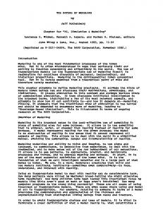
R is a set of graph transformation rules (given by pairs of object diagrams). In order to help the design and development of complicated software system, we develop an approach based on the GTS modeling and simulation (in Fig. 1). The approach is driven by a stepwise refinement between GTSbased models on different abstract levels. As shown in Fig. 1, a conceptual model is smaller and easier to understand; a concrete model reflects more design or implementation concerns. Starting from an abstract description of the systems, stepwise refinements yield more and more concrete specifications that should finally be directly implementable. Such method of defining models at different abstract layers is also fostered by MDA (Model-Driven Architecture) from the OMG. The definition of the model as platformindependent or platform-specific is rather relative. The conceptual model in Fig. 1 is platform-independent compared to the concrete model. The concrete model is platformspecific since it has a more specific design and realization. Besides this, the number of the abstract levels is not fixed as only two levels. More or less levels can be defined according to the complexity of the system and requirements of the models. For example, we define three-level abstract models in Sect. 3 in order to decrease the complexity of the styles. The operational semantics of the GTS allows us to execute the models and thus analyzing the system through simulation and model checking. Due to the well known state explosion problem with model checking, we prefer using simulation for analysis. Simulating the dynamic behavior of a high level architecture can implement the system in a quicker, cheaper, and more flexible way. Some desired information and properties can be gotten through the simulation of the architecture. The programmers can execute the system and have a direct feeling how the system works. We exploit the simulation to help testing and consistency checks between the conceptual and concrete models, where the wrapper and reference application are used for this purpose. They will be explained in Sect. 4.
Dynamic change > Platform Independent Concrete Style
Component Interactions and Dynamic change
> Platform Specific Concrete Style
3
Architectural styles for mobile computing middleware
More specific component interactions and Dynamic change
Conceptual Style Dynamic change Conceptual style of mobile computing platforms for nomadic networks >
In this section, we will illustrate the proposed approach through an example of how to specify architectural styles for mobile computing middleware. The main aspects of the middleware for mobile systems is explained in Sect. 3.1. Sect. 3.2. illustrates how to separate the aspects into different abstract levels of styles. Afterwards, we explain an example: styles of mobile computing middleware for nomadic network to show how to get a complete specification of a style by starting from a very abstract conceptual style (in Sect. 3.3), and then refining into a more design specific concrete style in Sect. 3.4 and Sect. 3.5.
3.1
Main characteristics of mobile computing middleware
When building architectural styles for mobile computing middleware, we need to identify the main properties to be modeled. Two important aspects: dynamic change and component interaction are explained here. 3.1.1
Dynamic change
Supporting for runtime modification is a key aspect of mobile computing platforms. Mobility represents a total meltdown [11] of the stability assumptions (e.g. network structure, network connection, power supply, CPU, etc.) associated with traditional distributed computing. The main differences are caused by the possibility of roaming and wireless connection. Roaming implies that, since devices can move to different locations, their context (network access, services, permissions, etc.) may change, and that mobile hosts are resource limited, for example, in computation power, memory capacity, and electrical power. Wireless connections are generally less reliable, more expensive, and provide smaller bandwidth, and they come in a variety of different technologies and protocols. This results in a very dynamic software architecture, where configurations and interactions have to be adapted to the changing context and relative location of components. 3.1.2
Component interaction
One important purpose of middleware is facilitating component interaction, and enabling the cooperation of distributed components. More specifically, component interaction covers component communication, collaboration, and coordination. These different aspects are not orthogonal and there is no clear boundary. For example, components need a method to communicate with each other through the network. The method can be message based, transactional
Concrete Style 1 (Platform-independent) Component interactions and Dynamic Change Concrete style based on RPC > Concrete Style 2 (Platform-Specific) Concrete Style of New Middleware
> Concrete Style 2 (Platform-Specific) Platform specific Component interactions and Dynamic Change Concrete Style of Wireless CORBA
> Concrete Style 1 (Platform-independent) Concrete style based on Publish-Subscribe > Concrete Style 2 (Platform-Specific) Concrete Style of REBECA
Figure 2. The modeling framework of styles for mobile computing middleware
based, event based, etc. The communication requires the coordination and synchronization between different actions and components, and the components collaborate with each other in order to perform a task. Middleware can be distinguished through the supported component interaction patterns and paradigms, e.g., RPC (Remote Procedure Call) pattern, message-based pattern, event-based pattern, etc. The static assumption of network structure, network connection and execution context in distributed systems makes the component interaction quite static. The components involved for interactions are generally fixed. Such fixed configurations will not change till a dynamic change happens. And the messages for communication are always supposed to be successfully transmitted by the network. In a mobile setting, the components involved in an interaction change dynamically due to their migration or connectivity patterns. This results in dynamic changes and reconfigurations among the components interaction.
3.2
The modeling framework for the styles
In order to define the style clearly and decrease the complexity brought by mobility, we will separate the styles into three abstract levels, i.e, the conceptual style and concrete styles in Fig. 2. The identified two properties: dynamic change and component interaction will be modeled on different abstract levels. The conceptual style will specify only the dynamic change of the components in the presence of mobility, but not the component interaction, for the reason that dynamic change is more general and abstract, while component interaction is more design specific. Different middleware platforms can support the same model of dynamic change, whereas the applied interaction models can be very different. For example, the conceptual style of mobile computing middleware for nomadic networks (in Fig. 2) can be refined into concrete styles that support different component interaction models, such as RPC and publishsubscribe model. Besides this, the conceptual model should
instanceOf nd1:NodeDef n1:Node
instanceOf n1:Node
nd1:NodeDef
connects
connect
:ConnectionDef connects instanceOf nd2:NodeDef n2:Node
connects instanceOf
connects
:ConnectionDef c:Connection connects instanceOf connects nd2:NodeDef n2:Node
handOver
Architecture Component 1 has
nd1:NodeDef
1 instanceOf
ComponentDef 1 supports 1 PortDef 2 connects
Port 2 connects Connector
instanceOf 1
ConnectorDef
NodeDef (fromConnectivity) 1 1 administrates locatedAt administrates
Area
instanceOf
1
AreaDef
Component (fromArchitecture)
n1:Node
NodeDef 1
instanceOf
1..*
ConnectionDef 1 1 uses ConnectorDef (fromArchitecture)
Node 2
instanceOf
provides Network 1..* instanceOf
connects
n3:Node locatedAt
connects
deployedAt
cr:Connector
connects
Node (fromConnectivity)
instanceOf
instanceOf ComponentDef (fromArchitecture) deployedAt
2
Roaming
locatedAt
connects connects nd2:NodeDef :ConnectionDef
nd1:NodeDef
connects :ConnectionDef
connects nd2:NodeDef
Connectivity
instanceOf
1 NetworkDef
uses
c1:Connection connects n2:Node
a1:Area
c2:Connection connects
administrates
uses cr:Connector
a2:Area locatedAt
instanceOf
instanceOf n1:Node
locatedAt a1:Area
instanceOf n3:Node
connects
locatedAt administrates
administrates
a2:Area n2:Node
administrates
Connection provides 1 uses
cr:Connector Figure 4. Rule: handOver of the conceptual connects style
Connector (fromArchitecture)
Figure 3. Meta model of the conceptual style Version 2: Without Bridge Defintition
1..*
provides
isConnectedTo Conceptual level: dynamic software architecture Bridges is responsible for the network connection in the answerlowthe following questions: What functionalities can layer.
be provides provided by such middleware? What application scenarios Concrete level 1: component interaction and dynamic architecture. on the middleware? can besoftware implemented Concrete level 2: one specific platform. On the concrete level, the conceptual style is refined into a concrete style, where more and more design-specific aspects like component interaction protocols and patterns are integrated into the core functionality. The concrete style also specifies dynamic changes of components involved in an interaction due to their migration or connectivity patterns. As a result, the dynamic change specified on the conceptual level will be associated with component interaction on the concrete level. The concrete style can be refined into a platform-specific style to add more implementation specific aspects. For example, the platform-independent concrete style based on RPC (in Fig. 2) can be refined into a platform-specific concrete style of Wireless CORBA, while the concrete style based on Publish-Subscribe can be refined into a concrete style of REBECA. We will explain the three-layer modeling approach through specifying the architectural styles of mobile computing middleware for nomadic networks. The corresponding three abstract layers will be illustrated in the following three sections.
3.3
Conceptual style
The conceptual style should define dynamic changes and main functionalities of a class of mobile computing middleware for nomadic networks. Nomadic networks utilize the infrastructure as access points to establish connectivity among mobile application components and to coordinate their transmissions. The nomadic network has a structured space where components are allowed to move inside the scope of areas covered by access points. Examples for such network are WLAN and telecommunication networks as GSM, GPRS, UTMS. The mobile computing middleware for nomadic network focuses on how to provide continuous connectivity and other services when components move across the structured spaces where handover protocols are
often used. Recalling the definition of the TGTS, G = hT G, C, Ri. The meta model (T G) of the style is shown in Fig. 3. We use a meta model structured into three packages. This allows us to separate different concerns, like software architecture, distribution, and roaming, while at the same time retaining an integrated representation. Our meta models capture these relations in the three packages Architecture, Connectivity and Roaming to present different viewpoints of the systems. The structured space of nomadic network is modeled as AreaDef in Roaming package. An area is defined by an administrative domain, like a cell managed by a GSM base station, or a Wireless LAN domain. The wireless connection is modeled as Connection in Connectivity package. Connection is a physical network link which delivers communication services to Connectors at the software level. The typing ConnectionDef means that we can distinguish, for example, between Ethernet, WLAN, or GSMbased connections. We define graph transformation rules (R): moveIn, moveOut, connect, disconnect and handOver. These rules are used to describe the dynamic changes and reconfigurations of the style in the presence of mobility. moveIn, moveOut model the movement of components, connect, disconnect model the connection and disconnection of wireless networks, and handOver models the main functionality handOver. As examples, we will introduce the rule handOver here, where the pre-conditions of the rule describe the situation must be satisfied when reconfiguration happens, and the post-conditions describe the results after the reconfiguration. The rule handOver (in Fig. 4) explains how to maintain connectivity between administrative domains. It requires that node n1 is located in two areas served by two administrative nodes n2 and n3. Connector cr uses connection c1 between node n1 and n2. The connection is replaced by c2 of type ConnectionDef which, according to the types declaration, is permitted between nodes of type NodeDef nd1 and nd2. The uses relation of the connector is transferred to the new connection.
1
deployedAt
NodeDef
ComponentDef 1 supports
2
provides
NetworkDef
1..*
connects
PortDef 2 connects uses
ConnectionDef 1
ConnectorDef
Sequence Dirgram2:UML2
app1:Component
Architecture TunnelDef uses 2 ClientDef
1
connects
ConnectionDef
manages 0..1 connects has associated 0..1 1 ComponentDef AreaDef supports (fromRoaming) knows 1..*
ComponentDef (fromArchitecture) 1..* 1..* 1..*
OperationDef (fromArchitecture)
( Events: MoveToArea)
encapsulates
contains 1
ParameterDef
server :Sever
app2:Component
sendRequestMBB request callReturn
moveToBridge handOver
MessageDef
sendReplyM
calls
1..* 1..* requires provides OperationDef
b2:Bridge
buildsTunnel sendRequestM
receives creates sendes
ServerDef
PortDef
b1:Bridge
remoteCall
(fromConnectivity)
BridgeDef
RoleDef
client :Client
Message
RequestMDef
CallMessageDef
reply
sendReplyMBB
respondsTo ResponseMDef 1 0..1
Figure 6. Sequence diagram for a remote invocation process
Figure 5. Meta model (partial) of the platform independent concrete style based on RPC
3.4
Platform-independent concrete style
After describing the conceptual model in Sect. 3.3, we will refine it into the concrete style that specifies designspecific component interaction with dynamic changes. The GTGS can specify the component communication and collaboration, while the coordination and synchronization between different actions and components can be specified using UML Interaction diagrams. We take the adapted RPC interaction models as our object of modeling to show how mobility influences the component interaction. RPC is used typically in middleware for distributed systems. Some middleware for nomadic network adapts the traditional RPC to fit for the mobility scenarios. RPC supports the definition of server components as RPC programs. A RPC program exports a number of parameterized procedures and associated parameter types. Clients that reside on other hosts can invoke those procedures across the network. RPC-based middleware provides compilers to automatically generate client and server stubs. The client stub is responsible for marshalling the parameters into a message, and sending them to the host where the server component is located. The server component unmarshalls the message and executes the procedure. Upon completion, it transmits marshalled results back to the client, if required. The RPC-based middleware for distributed systems only needs to define two components: client and server component. An invocation also involves only these two components. In order to support mobility in a nomadic network, more components are needed. Wireless CORBA supports terminal mobility through the concept of a bridge component that connects the mobile components to the fixed network side. We will use the same design idea in our model to support mobility. Handover will be used here to ensure continuous service between bridges when components move during the process of remote procedure calls.
The meta model of the conceptual style is extended to support component interaction RPC model. The architecture package in Fig. 5 defines more elements than in the conceptual style. Besides this, a Message package is created to support message definitions for calling a remote procedure. The other two packages Connectivity and Roaming in the conceptual style remain unchanged and are not shown here. Figure 5 only contains the Def part that defines the type meta classes like ComponentDef. The individual instance configuration is not included here. We suppose that every ”Def” class has a corresponding instanceOf associated meta class. Figure 6 defines the sequence of operations for one remote procedure call using a UML Interaction diagram1 . The semantics of operations is defined using graph transformation rules. The left side of the rule defines the precondition to execute the operation, where the right side of the rule defines the postcondition after executing the operation. The dynamic reconfiguration rules defined on the conceptual level will be directly used or adapted here. The MoveToArea event in Fig. 6 matches the moveTo operation in the conceptual level. The handOver rule has changed here. The definition of handOver on this level is more design specific. The purpose of handOver here is to provide continuous tunnels for transmitting messages between bridges. The abstract Connector in the conceptual style is refined into procedure calls, which will be encapsulated inside messages.
3.5
Platform-specific concrete style: CORBA
Wireless
After building the conceptual style and platformindependent concrete style in Sect. 3.4 and 3.5, we will take Wireless CORBA as an example to show how to evolve 1 We use UML 2 notations for Sequence diagrams in this paper. Filled arrowhead lines show a synchronous message, while stick arrowhead lines show an asynchronous message.
supports
1 ComponentDef
AreaDef (fromRoaming)
knows 1..* PortDef
calls
1..*
1..* requires provides OperationDef
a platform-independent concrete style into a platformspecific concrete style. In 2001, the Object Management Group (OMG) has adopted the Specification of Wireless Access and Terminal Mobility in CORBA [10], (Wireless CORBA, for short). It specifies the architecture and methods how CORBA can be used over wireless links. Wireless CORBA is a typical representation of the mobile computing middleware in a nomadic network. The main interaction paradigm in CORBA is distributed object requests that evolved from RPC. Distributed object requests means that a client object requests the execution of an operation from a server object that may reside on another host. In order to support mobility in nomadic networks, Wireless CORBA has adapted the distributed object requests, and more components are defined. Transparency of the mobility mechanism to non-mobile ORB is one of the primary design objective. Handover processes between different access bridge components are used to ensure that the invocation between clients and servers is kept consistent and the mobility is transparent to the applications. Handover will forward the messages for invocation (encapsulated inside GIOP messages) from an old attached access bridge to a new attached bridge. Such session-level handover is activated by the low-level handover notification issued from the wireless network. The home location agent will be responsible for tracing the current location (i.e. the attached access bridge) of the mobile terminal. Many components are involved to perform such a handover task, especially in the case when the terminal is moving across several access bridges. Following the wireless CORBA IDL specification, we distinguish three types of groups: Architecture packages, MobilityEvent group and GTP group. The Architecture group includes elements to construct the architecture of Wireless CORBA; MobilityEvent includes mobility service booking and notification; GTP includes the GTP message classification and delivery. Due to space limitations, we will only introduce the Architecture package here. The Architecture package in Fig. 7 contains classes that form the core of the Wireless CORBA architecture. The Architecture package adds more design-specific elements compared to the architecture package in Sect 3.4. The ComponentDef changes to ObjectDef. The PortDef, OperationDef, ParameterDef, ClientDef and Serveref remain the same, while other elements have been changed. Through using graph transformation rules, we can define the operation formally. Compared to the concrete model in Sect. 3.5, this platform-dependent concrete style based on wireless CORBA has more detailed design-specific information. Besides the extension of the meta model, the operations are refined into more detailed operations. For example, the handover operation in Sect. 3.5 is defined as
WCORBAModle contains 1
ParameterDef
Architecture trackedBy 1..*
ObjectReferenceDef
MobileIOR records
identifies
knows records
HomeLocationAgentDef 0..1 hosts
has
hosts TerminalBridgeDef
1 1 1 TerminalDomainDef
1 AccessBridgeDef 0..1
connects
HomeDomainDef
1
attachedTo accepted hosts
BridgeDef
VisitedDomainDef
DomainDef 1
ClientDef
RoleDef
playsRole1..*
ServerDef
ObjectDef 1 1 supports 1..* knows calls PortDef
1..*
has
1..* provides
OperationDef
contains 1
ParameterDef
Figure 7. Architecture package for wireless CORBA
one operation, while it is realized as a sequence of operations on this level.
4
Simulation
In this section, we will introduce three ways to use the simulation with Fujaba: for validating the model, for behavior consistency between different abstract levels, and as an oracle for test the actual implementation.
4.1
Simulation for validation
We have introduced in paper [7] how to use the existing graph transformation tools Fujaba [1] to simulate and validate the GTS based architectural styles. The object-oriented CASE tool Fujaba supports the specification of a system using UML class diagrams and Story diagrams, a combination of graph transformation rules and activity diagrams. Executable Java source code can be generated automatically. To observe the running system, a Dobs (Dynamic Object Browsing system) was developed. It supports the stepwise execution of rules by the Java Virtual Machine. At the same time it visualizes Java heap object structures as the current host graph. As input, the simulation tool (Dobs) requires a UML object diagram defining the initial state and a sequence of method calls. We can execute the models starting from the initial state according to the defined sequence of method calls. For example, we can test if the terminalinitiated handover scenario in the Wireless CORBA specification [10] is executable starting from the initial configuration, hence validating the functional completeness of our model.
From the execution result of the rules in Dobs, we can check if our specified system reacts in the desired way. In case of errors, we can go back to the original graph, divide the scenario into its atomic steps, and debug the system. The code used for the simulation can be used inside the running system as well, since Fujaba simulates the system by generating source code out of the specification and observing the running system. Such an approach closes the gap between the simulated system and the software running on the real system.
4.2
Wrapper for API–behavior consistency
The correct refinement of abstract conceptual styles into a concrete style is important, and the verification process is usually complicated. In order to automatize the consistency check between the conceptual and concrete models, we develop a Wrapper (in Fig. 1) to define the refinement relationship between these two models. Both the conceptual and the concrete model provide application programming interfaces through the operations defined via the rules, which are named Concrete API and Conceptual API as shown in Figure 1. As an adapter between Concrete API and Conceptual API, the wrapper encapsulates and maps the operations implemented in Concrete API to the operations defined in Conceptual API. Providing type transformation and semantic match, the Wrapper forwards operation calls to Conceptual API to the operation calls to Concrete API. In this way, the application can use the more abstract interface while the concrete operations offered by the platform remain hidden. This abstraction allows us to port the application to a new concrete platform API by means of a new wrapper, without changing the application itself. The wrapper can be also used to test, e.g., by means of a reference application, if the operations provided by Concrete API and Conceptual API are semantically compatible, therefore verifying the concrete style or the actual platform against the requirements expressed in the conceptual style.
4.3
Simulation for testing
All software testing methods depend on the availability of an oracle, that is, some methods for checking whether the system under test has behaved correctly on a particular execution. Executable formal specifications can be used as test oracles to produce the results expected for a test case. By comparing the result of a call to the actual implementation with the result of a call to the simulation, the test oracle can be used to check the correct execution of an operation. We can extend the specified platform-specific concrete model (e.g., Wireless CORBA model) to a test oracle. Since the concrete model is platform independent concerning the independency of specific programming languages, hardware
platforms and concrete implementation methods, it can be reused as a reference to test the correctness of implementations on different platforms. As a test driver, a standard reference application shall be required. To facilitate the interaction between the reference application with our model (resp., the code generated from it), we need to provide an Application Programming Interface(API) that is consistent to the API provided by a middleware implementation. Using the same test application as a test driver for the implementation and for the defined model, the developers can trace errors in the execution and check the pre- and postconditions of operations.
5
Related work
Paper [4] is quite close to our approach in the sense that they also use graph transformation systems to define architectural styles. They define the style as only fixed two layers: platform-independent and platform-specific style. While we deploy a framework that supports more flexible definition of the style, i.e., the number of the layer can be adjusted according to the complexity of the system. This fits better to the scenario of complex software systems, which needs generally more layers in order to define the styles clearly and decrease the complexity. Besides this, we deploy simulation of the GTS based on Fujaba to support validation, behavior consistency and testing of the implementation, which is not considered in [4]. Another main difference from [4] is caused by the target and content of the styles, thus the usage of the graph transformation system differs. Our style focuses on mobility definitions. Dynamic change and component interaction in the presence of mobility are our target. While the authors in [4] define styles for distributed systems, and mobility is not mentioned in this context. Regarding the architectural style for mobile computing middleware, there is nearly no work in this direction yet. We present how can define styles that capture the main aspects of middleware for mobile computing systems. We investigate the new requirements brought by mobility, i.e., the dynamic change and component interaction in the presence of mobility. Our approach varies greatly from the current architectural style approaches. The current architectural style approaches isolate the dynamic change specification from the component interaction specification. That means, they do not associate dynamic change with component interaction. Such approaches fit well to the static assumption of distributed systems, where dynamic change is only important to safety- or mission-critical systems. However, dynamic change is an important characteristics of mobile systems, and it also influences component interaction very much. In our approach, we associate the specification of dy-
namic change and component interaction. We specify dynamic change and functionalities on the conceptual level, while the concrete style defines the component interaction in the presence of dynamic changes. The dynamic change specified on the conceptual level will be refined into the concrete styles. Such association of dynamic change and component interaction would decrease the complexity brought by mobility, simplify the specification of styles for mobile systems, and help designers fully understand how mobility influences component interaction, and how the models evolve. There exist different specification and modeling methods of mobility in the software architecture area. Some of the techniques proposed by the AGILE project [3] are closer to our approach. AGILE develops an architectural approach by extending existing specification languages and methods to support mobility: UML stereotypes are used to extend UML class, sequence and activity diagrams in order to describe how mobile objects can migrate from one host to another, and how they can be hosts to other mobile objects. Graph transformation systems are proposed as a means to give operational semantics to these extensions. Other extensions are based on architectural description languages, like the parallel program design language CommUnity using graph transformation to describe the dynamic reconfiguration; Klaim is a programming language with coordination mechanisms for mobile components, services and resources; The specification language CASL as a means for providing architectural specification and verification mechanisms. While Klaim and CASL are more programming and verification-oriented, the approaches based on UML and CommUnity are at a level of abstraction similar to ours, but the goals are different: our focus is to model a style of mobile computing platforms, while the focus in the cited approaches is on the modeling of applications within a style that is more or less determined by the formalisms.
6
Conclusion and discussion
In this paper, we have presented an architectural stylebased approach to specifying and analyzing complex software systems. With a flexible definition of the architectural styles on different abstract levels, the approach supports the scalable modeling of a complex, huge system. We can specify and validate the architectural style using Fujaba, which focuses on the design and implementation phase. Fujaba has been proved successfully when used to specify and validate production control systems [9]. The simulation and debug support of Fujaba (Dobs) can greatly help the development of correct architectural styles and make such process efficient. In order to enhance the efficiency of our approach, one main point is to support automatic transformation between different abstract models, i.e., an abstract model can
be transformed into a refined model through specifying transformation (or refinement) rules. Our architectural style is specified using GTS, which allows a definition and formalization of such transformation rules. The authors of [4] have proposed a method to support half-automatic refinement through the help of model checking tools. The proposed approach is not suitable for huge systems due to the well known state explosion problem with model checking. We prefer using simulation as the basis for the transformation automatization, which can be developed as a plugin for Fujaba. This part is also one major issue of our future work.
References [1] From UML to Java and Back Again:. www.fujaba.de. [2] G. D. Abowd, R. Allen, and D. Garlan. Formalizing style to understand descriptions of software architecture. In ACM Transactions on SoftWare Engineering and Methodology. 4(4):319-364, Oct 1995. [3] L. Andrade, P. Baldan, and H. Baumeister. AGILE: Software architecture for mobility. In Recent Trends in Algebraic Develeopment, 16th Intl. Workshop (WADT 2002), volume 2755 of LNCS, Frauenchiemsee, 2003. Springer-Verlag. [4] L. Baresi, R. Heckel, S. Th¨one, and D. Varr´o. Modeling and validation of service-oriented architectures: Application vs. style. In P. Inverardi and J. Paakki, editors, Proc ESEC 2003: 9th European Software Engineering Conference, pages 68– 77, Helsinki, Finland, September 2003. ACM Press. [5] L. Capra, C. Mascolo, and W. Emmerich. Middleware for mobile computing. In Q. Mahmoud, editor, Middleware for Communications. John Wiley, 2002. [6] E. M. Dashofy, N. Medvidovic, and R. N. Taylor. Using offthe-shelf middleware to implement connectors in distributed software architectures. In 21st International Conference on Software Engineering, Los Angeles, CA, May 1999. [7] P. Guo and R. Heckel. Simulation and testing of mobile computing systems using fujaba. In 2004 Fujaba Days, Sept. 2004. [8] R. Heckel and P. Guo. Conceptual modeling of styles for mobile systems: A layered approach based on graph transformation. In IFIP TC8 Working Conference on Mobile Information Systems(MOBIS), pages 65–78, Sept. 2004. Oslo, Norway. [9] J. Koehler, H., U. Nickel, J. Niere, and A. Zuendorf. Integrating uml diagrams for production control systems. In 22nd International Conference on Software Engineering (ICSE), pages 241–251, 2000. ACM Press. [10] OMG. Wireless access and terminal mobility in CORBA, v1.0, 2003. [11] G.-C. Roman, G. P. Picco, and A. L. Murphy. Software engineering for mobility: A roadmap. In A. Finkelstein, editor, Proc. ICSE 2000: The Future of Software Engineering, pages 241– 258. ACM Press, 2000. [12] G. Rozenberg, editor. Handbook of Graph Grammars and Computing by Graph Transformation, Volume 1: Foundations. World Scientific, 1997.