BULETINUL INSTITUTULUI POLITEHNIC DIN IAŞI Publicat de Universitatea Tehnică „Gheorghe Asachi” din Iaşi Tomul LVI (LX), Fasc. 3, 2010 SecŃia AUTOMATICĂ şi CALCULATOARE
ARCHITECTURAL SUPPORT FOR SUBROUTINE EXECUTION TIME MONITORING IN EMBEDDED MICROPROCESSORS BY
ANDREI STAN, RADU CIORAP and FLORINA UNGUREANU
Abstract. Many embedded systems are used to implement safety critical applications that have to satisfy real time requirements. The real time requirements are derived from the functional characteristics of the physical system controlled by the application. In these systems, the correct operation as a whole depends also on the timeliness of the results. Results that are available earlier or later than a specified time, although they may be logically correct, they may cause unpredictable system behavior because of the timeliness violation. This paper presents the design of a digital module (watchdog) that may be included in embedded microprocessors in order to provide a mean to detect and signal the violation of timing characteristics of the executing code. The timing behavior monitoring is performed by measuring the execution time of subroutines and comparing the results with reference values. The proposed module does not require any modification of the monitored embedded microprocessor architecture. The module may be also used in non real time systems to implement security checking mechanisms by detecting various abnormal operating conditions that alter the execution time of subroutines (e.g. insertion of malicious/virus code). Key words: embedded systems, microprocessor architecture, security, watchdog. 2000 Mathematics Subject Classification: 68M01, 93C62.
1. Introduction Most embedded systems have stringent requirements for the safety and security characteristics due to their integration into safety critical systems. The failure of a safety critical system leads to unacceptable consequences with a negative impact on assets or even human lives. A failure is the manifestation or the effect of a fault in the system.
72
Andrei Stan, Radu Ciorap and Florina Ungureanu
The handling of the faults is performed at design time or at run time [1]. At design time, there are used certain methods in order to avoid the occurrence of faults in the system: repeated testing (practical method) or formal verification by using modeling and simulation (theoretical method). At run time, there are used some measures in order to tolerate the faults that were not detected and removed during design time. The safety and security characteristics of an embedded system may be dependent of the timing behavior of the running application. For example, in automotive industry the physical environment imposes the execution speed of the applications that are running on ECUs (Electronic Control Units). If the running application does not keep the pace with the environmental parameters rate of change then catastrophic consequences may occur. The timing behavior of a running application may influence other characteristics of the system, namely the quality of delivered service. For example, missing samples from a multimedia playback causes a low quality of the service. This is an example of a non safety critical application where the violation of timing characteristics decreases the performance of the application and may get to the point where the application generates an unusable output. The timing behavior of an embedded system is influenced by some factors [2]. Embedded systems are designed as reactive systems: they make intensive use of interrupts in order to quickly react to external triggered events. The interrupts may be seen as a source of unknown external interference. They are asynchronous events for the currently executing code and they usually have a higher priority, so the execution time for the service routines adds to the total execution time. The unpredictable nature of external interrupts represents a threat to the timing behavior of an application. Another factor that influences the timeliness of the operation of an embedded system is the communication process with other systems. Nowadays, more and more systems make use of distributed processing that includes multiple processing nodes and interconnection networks. The communication process may be easily disturbed by unknown interference that leads to packet corruption or loss. The limited knowledge and understanding of the external interference are the cause for the timeliness violation of embedded applications. In modern embedded microprocessors there are implemented many techniques aimed at improving the average performance: speculation, branch prediction, cache memories hierarchies and other. These methods enhance the average performance but they make the system very hard to analyze and to predict its behavior. It is true that for real time applications such architectural
Bul. Inst. Polit. Iaşi, t. LVI (LX), f. 3, 2010
73
features are not the main requirement. The choice of a microprocessor architecture for this kind of applications is driven by other criteria like predictability. The limited analyzability of a microprocessor architecture is another important cause for the timeliness violation for embedded applications. Because of the before mentioned reasons there is a need to design and implement mechanisms that detect and signal timing violations in embedded systems in order to avoid unwanted consequences. 2. Related Works There are numerous articles that present methods for checking the correctness of the code execution on microprocessors by using architectural enhancements. In paper [3] the authors present the concept of watchdog processors and highlight some implementations that were available at that time. A watchdog processor is a coprocessor that performs concurrent system-level error detection by monitoring the behavior of main processor. The information that watchdog processor uses to detect errors can be about: memory access behavior, control flow, control signals or the reasonableness of the results. The operation of a watchdog processor is a two phase process. First, the watchdog is provided with some information about the processor to be checked and second, it collects the relevant information concurrently as the main processor is running. Error detection is done by comparing the runtime acquired information with reference information provided at setup. For our monitoring device we use the same philosophy, but the information about the correctness of the operation is the execution time of the subroutines. The authors of paper [4] propose a methodology for embedding security monitoring technique within the microinstructions forming selfmonitoring instructions. There are created machine instructions that monitor themselves for improper operations via embedding extra microinstructions. The monitoring mechanism is applied to monitor: the return address for subroutines, the control flow instructions, data path of the microprocessor and the memory access. In paper [5] the authors present a hardware-based scheme to detect anomalies by checking program execution paths dynamically. The anomalous path checking mechanism is built into a secure processor that stores a record of whole program path (WPP) acquired in training phase. At runtime, the anomalies are detected by checking if the current executing path exists in the paths collected during training.
74
Andrei Stan, Radu Ciorap and Florina Ungureanu
The authors of paper [6] propose a dedicated hardware monitor that enforces permissible behavior as program executes. They present techniques to monitor the program behavior at different levels of granularity: the interprocedural control flow, the intra-procedural control flow and the integrity of instruction stream within each basic block (a block free of branches). The first two levels of the monitor are implemented using a Finite State Machine (FSM) that models the function call graph of the program or the control flow graph within a function. An invalid execution path is represented by a transition to invalid state or an invalid transition. The integrity of instruction stream is validated by using a cryptographic hash function of the instructions in a basic block. Hash values are computed beforehand, loaded into the hardware monitor and checked during program execution. In paper [7] the authors propose an approach that extends the embedded microprocessors with hardware that significantly accelerates the execution of the additional computations involved in memory-safe execution by designing custom instructions that perform various memory safety checks. In order to augment the original architecture with error detection mechanisms, all the previous presented solutions include a customized design flow or methodology for the applications to take advantage of the new added features. 3. The Detection and FP Rate The monitoring module (watchdog – WDT) is connected to the microprocessor address bus and to the instruction bus, as presented in Fig. 1. It signals abnormal operation by issuing control signals like reset, interrupt or NMI or issuing appropriate opcodes on the instruction bus. The monitoring module is built using the following data structures and algorithms. The watchdog stack (WS) is a last in first out data structure that stores the called subroutines starting addresses. The top of the WS contains the starting address of the last called subroutine. This data structure is used to easily retrieve the last called subroutine starting address when a return instruction is detected on the instruction bus. Execution Time Counters – this component is made by a counter array; each counter may be individually selected in order to reset its internal value or to enable or disable its operation (counting). Each monitored subroutine has a corresponding execution time counter. The number of counters limits the number of simultaneously monitored subroutines, but it may be appropriately chosen to fit the application needs.
Bul. Inst. Polit. Iaşi, t. LVI (LX), f. 3, 2010
75
Fig. 1 – Monitoring architecture.
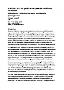
The watchdog uses a table – named Monitoring Info Table (MIT) – with information about the expected timing behavior of all or only critical subroutines of the application. The table contains the starting address of the monitored subroutines, the index of the timer from the counter array used to monitor the timing behavior and the values of four parameters that describe the timing behavior of the subroutine, as presented in Fig. 2: a) Lower timing bound (LTB) – the minimum acceptable execution time; b) Best case execution time (BCET) – the minimum execution time computed by simulation or by testing; c) Worst case execution time (WCET) – the maximum execution time computed by simulation or by testing; d) Upper timing bound (UTB) – the maximum acceptable execution time.
Fig. 2 – Timing characteristics of a subroutine.
These values define five possible domains for the execution time of a subroutine as presented in the Fig. 2. The acceptable domain for execution time is defined by the difference between UTB and LTB. All other values for
76
Andrei Stan, Radu Ciorap and Florina Ungureanu
execution time that exceed UTB or are lower than LTB are unacceptable values for systems with real time requirements or may indicate abnormal timing behavior. This situation may be called a timing exception for a real time system. This event may be of equal value or importance as it is overflow and division by 0 for arithmetic operations and ultimately for the correct/safe/secure operation of the system. If arithmetic exceptions, like those mentioned above, signal a possible corrupted or wrong numeric value, the timing exception, in the context of real time systems, may signal an obsolete data being used because additional unwanted delay added between the moment the data was produced and the moment the data it is used. This may have a catastrophic impact on system operation. The watchdog module monitors the address bus for code memory and the instruction extracted from code memory. The watchdog decodes the instruction in order to detect subroutine calls and the matching return from subroutine instructions. When a timing violation occurs this triggers a handling mechanism. There are three possible handling mechanisms: a) Reset the MCU – this is the usual method that a classic watchdog uses; b) Issues a NMI or INT to the MCU – this method may be used if a handling mechanism is implemented in software as a handling routine for NMI interrupt or INT; c) Insert an instruction or sequence of instructions to the MCU – the inserted instructions may be a call or a jump to a handling routine; this mechanism is similar with the NMI interrupt, but it is more flexible by allowing a specific handling routine for timing violation for each subroutine. The watchdog uses a finite state machine to sequence the operations need by its operation. The inputs of the state machine are condition signals generated by logical operations between the values of WS, MIT, address bus, instruction bus, as explained below. The outputs of the finite state machine are control signals. The operation of the watchdog is presented in Fig. 3.
Fig. 3 – State chart for the FSM of the monitoring module.
Bul. Inst. Polit. Iaşi, t. LVI (LX), f. 3, 2010
77
The initial state of the watchdog is IDLE state. In this state, the watchdog monitors the instruction bus and also checks the state of execution time counters for monitored subroutines. There are three possible transitions from this state. The transitions are discussed next in the decreasing order of their priorities. If one execution time counter reaches a value greater than corresponding WCET then a transition to the exception handling state is performed. If the instruction currently fetched is a CALL instruction, then a transition to the setup monitoring state for the called subroutine. If the instruction currently fetched is a RET instruction, then the value of the counter is compared with the BCET of the returning subroutine. If this value is lower than BCET then a transition to the exception handling state is performed, otherwise a transition to the end monitoring state for the currently monitored subroutine is performed. The setup monitoring state (TMR STA) checks if the called subroutine needs to be monitored. This is done by searching subroutine starting address (the address field in the call instruction) in the MIT. If the address is found, then the corresponding execution time counter is started and the starting address is stored on the top of the WS. The only transition from this state is to the IDLE state and it takes place when the setup is done. The end monitoring state (TMR STP) extracts the value from the watchdog stack and stops the execution time counter associated with the returning subroutine. A transition to IDLE state is performed. The operation explained before assumes that the return instruction detected on the instruction bus correspond to the last called subroutine (a normal sequence of operation). The development of an application that takes advantage of this monitoring architecture must follow a specific flow. The software is designed and implemented first. In order to generate the monitoring module, the critical subroutines must be determined and after that their execution time characteristics must be computed. This may be accomplished by using static analysis [8] or by repeated testing. With the information provided in this stage, the monitoring module may be generated and together with the binary of the application the final architecture is implemented. The design flow is presented in Fig. 4.
78
Andrei Stan, Radu Ciorap and Florina Ungureanu
Fig. 4 – The design flow.
4. Conclusions The implemented monitoring module offers a mechanism that allows the dynamic checking of the time behavior of subroutines. In order to evaluate the monitoring module, we used the Spartan3E FPGA from Xilinx and a very simple soft-core processor: PicoBlaze. This is a constant coded programmable state machine which is designed and optimized by Xilinx for its FPGAs: this is a machine based on constants which are allowed to be specified within any instruction word. We designed two scenarios: in the first we synthesized only the PicoBlaze and in the second we augmented the first design with the watchdog module. The cost for implementing the two scenarios is presented in Table 1. The table presents the quantity of FPGA digital resources required by the two implementations. We notice that the actually implemented monitoring module uses significantly more resources compared to the processor alone. This can be explained by the simplicity of the soft-core processor and by the fact that this processor is highly optimized for FPGA implementation.
79
Bul. Inst. Polit. Iaşi, t. LVI (LX), f. 3, 2010
Table 1 Logic Utilisation and Frequency Picoblaze Alone
Picoblaze and WDT
Number of Slice Flip Flops
76
129
Number of 4 input LUTs
176
411
Number of occupied slices
98
236
Operating frequency (MHz)
116.136
93.092
Resources
The monitoring module (WDT) uses a lot of memory resources – see Table 1 – in order to implement the stack and also to store the relevant timing information for each monitored subroutine. The monitoring module uses logic resources to implement large and numerous comparators for address matching logic. The degradation of the maximum operating frequency also may be observed. This fact is due the existence of a critical path in the implementation of the stack inside the monitoring module. This may be eliminated by redesigning the stack or by specifying additional constraints for the synthesis process (or even change the synthesis tools). For more complex processors we expect that the resource overhead required by the implementation of our monitoring module to be less significant. Further work is aimed at implementing the monitoring module into more complex microprocessors architectures like MicroBlaze, OpenRISC or SPARK T1 or T2. Also, a mechanism for handling indirect subroutine calls should be designed. A c k n o w l e d g e m e n t s. This work is supported by Romanian Minister of Education, Research and Innovation in the framework of National Program for Research, Development and Innovation (PNCDI-2) under partnership project no. 11070 SIMPA. Received: March 29, 2010
“Gheorghe Asachi” Technical University of Iaşi, Department of Computer Engineering e-mail:
[email protected]
REFERENCES 1. Salewski F., Tylor A., Fault Handling in FPGAs and Microcontrollers in SafetyCritical Embedded Applications – A Comparative Survey. 10th Euromicro Conf. on Digital Syst. Design, Lübeck, Germany, 124–131 (2007).
80
Andrei Stan, Radu Ciorap and Florina Ungureanu
2. Thiele L., Wilhelm R., Design for Timing Predictability. J. of Real Time Syst., Kluwer Acad. Publ., 2004. 3. Mahmood A., McCluskey E.J., Concurrent Error Detection Using Watchdog Processors – A Survey. IEEE Trans. on Comp., 37, 2, 1988. 4. Ragel R.G., Parameswaran S., Mohammad Kia S., Micro Embedded Monitoring for Security in Application Specific Instruction-set Precessors. Proc. of Intl. Conf. on Compilers, Architectures and Synthesis for Embedded Syst., San Francisco, 304–314 (2005). 5. Zhang T., Zhuang X., Pande S., Anomalous Path Detection with Hardware Support. Proc. of Intl. Conf. on Compilers, Architectures and Synthesis for Embedded Syst., San Francisco, 43 – 54 (2005). 6. Arora D., Raghunathan A., Jha N.K., Architectural Support for Safe Software Execution on Embedded Processors. Proc. of 4th Intl. Conf. on Hardware/ Software Codesign and Syst. Synthesis, Seoul, 106–111 (2006). 7. Arora D., Ravi S., Raghunathan A.A., Jha N., Secure Embedded Processing through Hardware-assisted Run-time Monitoring. Proc. of the Conf. on Design, Automation and Test in Europe, 1, Munich, 178–183 (2005). 8. Wilhelm R., The Worst-Case Execution Time Problem – Overview of Methods and Survey of Tools. ACM Trans. on Embedded Comp. Syst., 7, 3, 2008.
ARHITECTURA SUPORT PENTRU MONITORIZAREA TIMPULUI DE EXECUłIE A SUBRUTINELOR PENTRU MICROPROCESOARE ÎNCORPORATE (Rezumat) Multe sisteme încorporate sunt utilizate pentru a implementa aplicaŃii cu securitate critică şi care trebuie să satisfacă cerinŃele impuse de lucru în timp real. CerinŃele de timp real rezultă din caracteristicile funcŃionale ale sistemului fizic pe care rulează aplicaŃia software. În aceste sisteme, funcŃionarea corectă în ansamblu depinde de durata obŃinerii rezultatelor. Rezultatele care sunt disponibile mai devreme sau mai târziu faŃă de momentul specificat, deşi par corecte din punct de vedere logic, pot determina o comportare nepredictibilă a sistemului datorită violării programării în timp a evenimentelor. Această lucrare prezintă structura unui modul digital, denumit watchdog, ce poate fi inclus în microprocesoare încorporate cu scopul de a oferi o modalitate pentru detecŃia şi semnalarea cazurilor de violare a digramelor de timp aferente execuŃiei codului. Monitorizarea comportării în timp real se realizează prin măsurarea timpului de execuŃie a subrutinelor şi comparrea rezultatelor obŃinute cu valorile de referinŃă. Modulul propus nu implică nici o modificare a arhitecturii microprocesorului încorporat monitorizat. De asemenea, modulul poate fi utilizat şi pentru sisteme ce nu funcŃionează în timp real pentru a implemeta mecanismele de verificare a securităŃii prin detecŃia condiŃiilor de operare anormale reflectate prin modificarea timpului de execuŃie a subrutinelor.