Architecture and Configuration of Broadband Access Networks Supporting. Multimedia ... application service provider (ASP) network, that possibly have its own ...
Architecture and Configuration of Broadband Access Networks Supporting Multimedia Applications∗ András Kern, Mátyás Martinecz, Zalán Heszberger and Gyula Sallai Department of Telecommunication and Media Informatics Budapest University of Technology and Economics 2. Magyar tudósok körútja Budapest, Hungary, H-1117 {kern, martinecz, heszberger, sallai}@tmit.bme.hu
Abstract Recent Internet access speeds have made it possible even for home users to reach and use previously unavailable bandwidth consuming (e.g. Video on Demand) services. However, the rapid spread of these applications is hindered by the lack of QoS guarantees in packet networks. In this article a QoS architecture is presented which have been designed for access networks and applies a logical overlay network to make network management tasks easier. The novelty of the architecture lies in the application of two key procedures adopted for dimensioning logical channels between edge nodes and mapping them to the physical routes. The upper load thresholds of the applied logical channels are also determined, which may form the basis of a more sophisticated call admission control policy.
1 Introduction Recent Internet access speeds have made it possible even for home users to reach and use previously unavailable value-added, bandwidth consuming (e.g. Video on Demand) services. The rising demand for these applications urge the solution of QoS provisioning in packet networks, as without guaranteed service quality level the rapid spread of these novel applications is unlikely. To solve this problem network management mechanisms should be implemented into the network. The first step towards the aim of QoS provision for Internet services should be the provision of QoS guarantees in the access network (AN). Therefore a robust access network should be developed implementing an efficient QoS architecture capable of guaranteeing a proper level of transmission quality for value-added services. ∗ This work was supported by the Inter University Centre for Telecommunications and Informatics.
A framework called Enhanced Resource and Information Control (ENRICO) has been developed to solve this problem [1]. According to this concept a central bandwidth broker manages the access network’s resources by making call admission control (CAC) decisions and bandwidth allocations. To make network management tasks easier a simpler logical overlay network is defined onto the physical topology. In our research work the ENRICO model was regarded as a starting point, but it has been altered in several aspects. Instead of the centralized CAC entity a distributed traffic load control scheme is recommended which is realized by the edge nodes of the AN. Furthermore, new concepts have been introduced in the implementation of the logical overlay network. The main contribution of the paper is built around these points. The realization of the logical overlay network in the AN raises two important questions: special algorithms are needed to the dimensioning of the logical channels and also methods are to be developed to map these channels to the physical routes. The importance of determining the maximum capacity of each logical channel is also emphasized, as this value can form the basis of a more sophisticated CAC policy. Such procedure is also suggested in the paper. The rest of this paper is organized as follows. In the following section the QoS architecture to be applied in the AN is introduced in details. The third section contains the description of a method that may be used to determine the required capacity of the logical channels. In the fourth section the technique that maps logical channels onto physical routes and determines maximal capacity of those is presented. The fifth section contains an illustrative, numerical example which aids the understanding of the benefits and operation of the presented methods. Our concluding remarks can be found in the last section.
Proceedings of the 10th IEEE Symposium on Computers and Communications (ISCC 2005) 1530-1346/05 $20.00 © 2005 IEEE Authorized licensed use limited to: BME OMIKK. Downloaded on November 21, 2008 at 09:36 from IEEE Xplore. Restrictions apply.
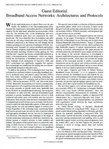
2 ENRICO Based Model In general, network traffic belonging to the session of a value added application may travel along three different networks until reaching the destination located at the subscriber’s home network: For first, as a typical source, the application service provider (ASP) network, that possibly have its own storage area subnetwork consisting of multiple interconnected servers. For second, the network of the internet service provider (ISP), which typically consists of routers, AAA server(s), mail server(s), etc. Accordingly the main tasks of the ISPs are to offer connectivity for ASPs to the AN, to authorize and to authenticate access. Finally, the AN, which consists of the local loop and the aggregation network. However, this paper focuses only on a segment of the aggregation network, the boundaries of which are defined by the DSLAMs (DSL Access Multiplexers) and the BASs (Broadband Access Servers). The QoS architecture introduced in this article is based on the ENRICO concept [1] and has been designed for QoS provisioning primarily in DSL access networks. In this concept an interface is provided between the NAP and the ASP through which QoS- and resource reservation-related information may be exchanged in a manner that is fully transparent to subscribers. Load control functions (call admission control, traffic policing) are realized by the edge nodes of the AN in a distributed manner. Resource reservation operations are carried out however by a central configurator entity, which defines a logical overlay network onto the physical one in advance. This predefined overlay network consists of logical point-to-point trunks between the edge nodes of the AN. For gathering the needed information for the operation of the QoS architecture certain functions of currently available protocols such as the RSVP or the DHCP are also exploited. To make the whole concept clearer let us see its operation step by step (see Figure 1). The following example depicts a value-added service provisioning through the DSL-based AN applying the above detailed architecture: Step 0. The central configurator entity defines the logical overlay network, that is it configures a logical channel between each DSLAM and BAS per QoS class. These QoS pipes can be realized either by PVPs (Permanent Virtual Paths) in case the L2 technology of the aggregation is ATM, or by exploiting the ELS (Ethernet Line Service) in case L2 technology is Ethernet. For more details see [1]. Step 1. A new subscriber would like to connect to the Internet, therefore it requests an IP address from its ISP using the DHCP. This DHCP communication is monitored by the BAS through which the subscriber can reach its ISP and important pieces of information (subscriber’s IP address, the DSLAM to which the subscriber’s DSL is connected) are stored by the BAS.
Step 2. The subscriber initiates a value-added service (e.g. VoD) through the web page of the ASP by simply clicking on the appropriate hyperlink. Step 3. The ASP registers the request and sends an RSVP packet to the subscriber. This RSVP message describes the desired QoS level of the service and also contains the peak transmission rate of the traffic generated by the initiated session. Step 4. The BAS captures the RSVP packet and according to the encapsulated information checks whether there is enough capacity available in the appropriate QoS pipe to fulfil the QoS requirement of the newcomer and already admitted sessions at the same time. Step 5.a If there is enough available capacity the newcomer session is admitted: it is registered by the BAS and the policers of the BAS and the subscriber’s DSLAM are set according to the peak transmission rate of the new session. Step 5.b In case the predefined QoS pipe has not enough available capacity for the newcomer session then the capacity of the pipe should be expanded if possible. As the maximum sizes of the logical channels are previously determined by the configurator entity this question can be easily answered. In case the currently allocated capacity for the QoS pipe is less than its maximum size it should be expanded to a higher value so that it could cope with the new session as well. Step 5.c. In case the capacity of the appropriate QoS pipe is not enough to cope with the currently active plus the newcomer session and the pipe cannot be expanded the service request must be rejected and the ASP’s server should be informed about this decision. Service request
WWW Server 1
4
2
5
Config entity
3
6
7
8
9
*
8
#
VoD server
Modem
Resource request
Granted
ASP network
Home network DSLAM
BAS Switch
Access Network
POP3 Server
AAA server
ISP network
Figure 1. The model of the recommended QoS architecture
Obviously the predefined logical overlay network plays a central role in this architecture. For its realization two main questions have to be answered. The first one deals with the dimensioning of the logical channels, that is how much capacity should be allocated for each QoS pipes provided
Proceedings of the 10th IEEE Symposium on Computers and Communications (ISCC 2005) 1530-1346/05 $20.00 © 2005 IEEE Authorized licensed use limited to: BME OMIKK. Downloaded on November 21, 2008 at 09:36 from IEEE Xplore. Restrictions apply.
that an anticipated traffic load and a target QoS level per QoS class is defined. The other question is how to map these logical channels onto physical routes. Besides these two questions it is also worth investigating what the maximum capacities of the logical channels are. This result can be useful for the network operator in two fields. First, in the already mentioned case when the traffic load gets higher than anticipated, it provides information about how many spare capacities could be allocated to expand the predefined logical channels so that they could cope with the extra traffic. Second, if the AN operator would like to expand its subscriber population without extending the currently available physical capacities, then from the maximum logical channel capacities the maximum number of subscribers at each DSLAM could be educed. In the next two sections we recommend methods that can be used for realizing the above mentioned three functions of the central configurator entity.
3 Logical Channel Dimensioning One of the most important questions arising in connection with the logical overlay network deals with the required capacities of the logical channels. To answer this question a method will be presented that bases only minimal given parameters: it is supposed that only the number of subscribers per DSLAM, their rate of service initiation, the mean holding time of the sessions and the peak and mean transmission rates of the service are known. Let us suppose that the AN contains k DSLAMs and the number of subscribers connected to DSLAMi , denoted by Ni , i = 1 . . . k is known. Let us also assume that the subscribers request a certain type of service independently from each other and with probability p. Thus service requests arriving at DSLAMi can be modelled with a Poisson process of rate λi = Ni ∗ p. The mean value of the holding time of the service is denoted by h. Using Erlang’s B formula the minimal number of channels that is required to stay below a target blocking probability ε can be computed as follows:
keeping delay and jitter at as low level as possible. In the Bufferless Fluid Flow Multiplexing (bffm) framework multiplexed traffic sources are regarded as an aggregated fluid flow flowing through a bufferless link with capacity C. This means that information loss only occurs when the instantaneous arrival rate of the aggregated flow exceeds C. This approach does not describe real life perfectly, as real packet schedulers start serving a packet only after it has totally arrived and only one packet is served at a time, however using this framework a conservative bound on the expected P LR can be determined and only minimal buffer sizes are needed to avoid packet drops occurring at simultaneous packet arrivals. In the applied model n fluid flows are aggregated onto a communication link (i.e. a QoS pipe) with capacity C [2]. Let Xi (i = 1 . . . n) be random variables denoting the instantaneous arrival rate of the ith stationary flow. It is assumed that the composition (i.e. ratio of certain traffic source types) of the anticipated aggregated traffic is known however only limited amount of data is available about each type of traffic sources: they are characterized by their pi peak and mi mean arrival rate . Let X random variable �n denote the arrival rate of the aggregated traffic X = i=1 Xi . Thus the value of packet loss ratio can def
be expressed: PLR = E[(X − C)+ ]/E[X], where E[.] stands for the expectation value operator and (X − C)+ = max(X − C, 0). The goal is to determine the equivalent capacity of X, which is by definition: def
Cequ,P LR = inf{C : WLR ≤ e−γ }.
It can be seen that for the evaluation of (2) the expected P LR should be determined somehow. As only two parameters of the traffic sources are known it can not be calculated exactly however it can be bounded from above using the well-known Chernoff inequality [2, 3]: PLR ≤ inf exp (ΛX (s) − sC − log(sM )) . s>0
� ci,min = inf
ρci /c!
c : E(ρi , c) = �c
j=0
ρji /j!
� ≤ε
(2)
(3)
def
(1)
where ρi = λi ∗ h is the offered traffic at DSLAMi , traditionally measured in Erlangs. The question is now that how much capacity is needed to transmit ci,min simultaneous sessions while fulfilling their QoS requirements composed in terms of delay, delay variation and information loss. To answer this question a simple modelling approach may be applied with the aid of which quantitative guarantees can be provided for the PLR (Packet Loss Ratio, e.g. the ratio of lost and sent packets) while
where ΛX (s) = log E[exp(sX)] is the logarithm of the moment generating function (M GF ) of X. The M GF of X can not be determined exactly, as only the mean and peak rate of a traffic source are known, however if the original traffic sources are substituted with their ON/OFF equivalents and the possibly inhomogeneous sources are homogenized a simple upper bound for the MGF of the original aggregated flow’s rate distribution function can be constructed [4]: ranTheorem 1 Let X1 , . . . , Xn indicate n independent �n dom variables with 0 ≤ Xi ≤ pi , X = i=1 Xi and
Proceedings of the 10th IEEE Symposium on Computers and Communications (ISCC 2005) 1530-1346/05 $20.00 © 2005 IEEE Authorized licensed use limited to: BME OMIKK. Downloaded on November 21, 2008 at 09:36 from IEEE Xplore. Restrictions apply.
M = E[X]. Let Y1onoff , . . . , Ynonoff be nY independent Y homogeneous on-off sources with the �nidentical peak rate . . , n), nY = � i=1 pi /p�, and idenp = max(pi , i = 1, . � n tical mean rate m = i=1 mi /nY . Then for s > 0, E[exp(sX)] ≤
� �n M sp Y M e 1− + nY p nY p
(4)
For proof of Theorem 1 see [5]. Using (3) and (4) the following direct equivalent capacity bound can be constructed [6]:
a common 155 Mbit/s link. For two pipes only 1010 Mbit/s are assigned and the remaining capacity is allocated (135 Mbit/s) for the third pipe. To prevent this distribution, the minimum of bandwidth of these pipes should be also maximized. However, this latter policy does not distribute the remaining free network capacities after it maximized this bandwidth minimum. This problem becomes crucial, when the network has bottlenecks. Therefore, we have to introduce an additional policy, which punishes the longer pipes.
4.1 Formal model � X,so (s) + γ − log(sM ) Λ C˜equ,P LR = inf , s>0 s
(5)
� X,so (s) is the logarithm of the MGF bound prewhere Λ sented in (4). It is worth noting here that this expression contains only one optimization, which can be performed rapidly.
4 Network Configuration Task The main goal of this task is to allocate capacities and determine the maximal sizes for the logical pipes in the physical networks. Since a central entity performs this operation, the global view of the network state is known. A possible solution is to tune sharp the sizes of the pipes applying an iterative method [7]: the sizes of the pipes are decreased if the configurator cannot solve the problem and increased if it can and free capacities remain in the network. On the contrary, in the proposed approach, these two tasks (path allocation and pipe sizing) are handled at the same time. The goal is to maximize the throughput of the system instead of minimize the allocated network capacity. To achieve this, elastic pipes are assumed, i.e. the size of the pipe can be changed between bounds. The required traffic determined during the logical channel dimensioning task appears as lower bound for the pipe. Is is possible to define an upper bound for the pipe but it is not necessary. However, the problem of how to distribute the bandwidth among the demands brings up the issue of fairness. Vast number of different fairness policies can be defined. In [7] the authors present different fairness considerations and detail the relation among the fairness, the available throughput and the required computational time. Our aim is to maximize the network throughput to serve unexpected demands, however unequal capacity distribution and pipe starvation should be avoided. These requirements meet the definition of the max-min fairness presented in [7]. The throughput maximization alone is not able to avoid the unequal capacity distribution. For instance, if three pipes (with 10 Mbit/s minimal bandwidth) are routed on
Let G(V, L, C) be a directed graph, where V is the set of routers, L is the set of links. VDSLAM ∈ V and VBAS ∈ V define the sets of the DSLAMs and BASs. Full-duplex links are assumed; however, the graph G remains directed in order to describe asymmetric traffic. Therefore a link is modelled with two opposite edges. The amount of allocated capacity on the link will be the maximum of the load of the two opposite link. In the model presented above, a pipe is assigned to each QoS class between every pairs of DSLAMs and BASs. The requirements of a pipe are also called as demand. Let D be the set of these demands. Each demand d ∈ D has the following attributes: source (s(d) ∈ VDSLAM ), destination (t(d) ∈ VBAS ), minimal required bandwidth (B d ) and traffic unit size (bd ). The minimal required bandwidth is determined with the aid of (5) for each QoS pipe. The method can allocate integer multiple of this traffic unit. The Integer Linear Programming (ILP) formulations is based on network flow models [8]. The notation is as follows:
D N L cl Bd bd nd xdl
Input parameters set of demands set of nodes set of links available capacity of link l ∈ L minimal required bandwidth for each demand d ∈ D (according to Eq. 5) size of the traffic unit for each demand d ∈ D Solution (variables) number of traffic units allocated for demand d ∈ D number of traffic units routed for demand d ∈ D is routed on link l ∈ L
The objective is to maximize the following function derived from the combination of fairness policies presented above: n+
�
nd b d − c − α
d∈D
��
xdl
(6)
l∈L d∈D
Two additional variables (n and c) are introduced to im-
Proceedings of the 10th IEEE Symposium on Computers and Communications (ISCC 2005) 1530-1346/05 $20.00 © 2005 IEEE Authorized licensed use limited to: BME OMIKK. Downloaded on November 21, 2008 at 09:36 from IEEE Xplore. Restrictions apply.
plement the previously defined fairness policies. The constraints are the following. Flow conservation constraints The aim of these constraints are to ensure that traffic demands reach their destinations. Constraint (7) is the well known flow conservation equation. The model supports load sharing, i.e., may define more than one routes between source and destination nodes. The inequalities in (8) says that on a single link we cannot allocate more traffic units for a demand than its total traffic units. �
xdij
∀j∈N i→
−
�
xdki
=
∀j∈N →i
nd −nd 0
if i = s(d) if i = t(d) , otherwise
∀i ∈ N and d ∈ D xdl ≤ nd ,
∀d ∈ D ∀l ∈ L
Figure 2. Sample network topology (7)
5 Numerical Example
(8)
In previous sections we presented a framework for ensuring QoS in broadband access networks and presented techniques for defining a logical overlay network onto the physical one. In this section we try to shed more light on the process of the configuration task through a simple numerical example. Extensive simulations and comparison with other methods are planned to be performed later. Figure 2 shows the physical topology of the sample network. On the left side there are 11 DSLAMs. The DSLAMs can be categorized into three classes: city (DSLAM #12– #18), suburban (DSLAM #22–#24) and rural (DSLAM #25–#26). For the sake of simplicity now the BASs are the content provider servers: a VoD server and a VoIP gateway. The link capacities are also shown on the figure. For the subscribers three services are provided: voice (VoIP), video on demand (VoD) and best effort. Capacity for unexpected VoIP calls are not ensured, thus, they can be described as rigid traffic (the lower and upper bound of the QoS pipes transporting VoIP traffic are the same). The best effort traffic (BET) uses the remaining free capacity in the network. Therefore, between every pairs of DSLAMs and BASs two logical channels are defined: one for the video and an other for the voice traffic. The properties of the DSLAMs depend on its class. First of all, the numbers of connected subscribers are 250, 150 and 100 for city, suburban and rural classes respectively. Moreover, in the first two cases, the probability of initiating a new VoD demand is higher. All parameters of the DSLAM classes are presented in Table 1. The first task is to determine the number of simultaneous VoD and VoIP demands. To calculate them Eq. 1 is applied. In the current example the blocking probabilities of VoD and VoIP are set to 0.01 and 0.001. For instance 33 VoD channels are needed in case of suburban DSLAMs. Although the number of simultaneous channels are de-
Demand size constraints Since elastic pipes are assumed introduction of bounds are necessary. In (5), for each demand, an exact lower bound is determined during pipe dimensioning task. This bound is defined with constraint (9). On the contrary, there is no given upper bound, however the available capacity on the links defines such a bound. It is obvious that more bandwidth on a link cannot be allocated than its total capacity. This rule is described in (12). bd · nd ≥ B d , �
xdl · bd ≤ cl ,
∀d ∈ D ∀l ∈ L
(9) (10)
d∈D
Fairness description To implement the fairness policy defined above, additional variables were introduced. Parameter n is responsible for preventing unequal capacity distribution. The inequalities of (11) indicate that the number of allocated traffic units has to be greater than n. Formula (12) describes thatn parameter c is an upper bound for the allocated capacity of a demand. bd · nd ≥ n, �
xdl · bd ≤ c,
∀d ∈ D ∀d ∈ D
(11) (12)
l∈L
Type restriction xdl nd
≥ 0 integer, ∀d ∈ D and ∀l ∈ L ≥ 0 integer, ∀d ∈ D
(13) (14)
Proceedings of the 10th IEEE Symposium on Computers and Communications (ISCC 2005) 1530-1346/05 $20.00 © 2005 IEEE Authorized licensed use limited to: BME OMIKK. Downloaded on November 21, 2008 at 09:36 from IEEE Xplore. Restrictions apply.
Table 1. Required number of simultaneous VoD/VoIP channels and amounts of equipment capacities. DSLAM class City Suburb Rural City Suburb Rural
Number p h # of of Users (n) channels VoD traffic class (Pblock = 0.01) 250 0.2/120 90 50 150 0.2/120 90 33 100 0.1/120 90 15 VoIP traffic class (Pblock = 0.001) 250 0.5/60 5 22 150 0.5/60 5 16 100 0.5/60 5 12
CEqu [kbit/s] 61624 45146 26094 499 369 281
Table 2. Offered number of simultaneous VoD and VoIP calls (PLR = 1%) DSLAM type City Suburb Rural 1 Rural 2
CEqu [kbit/s] 61624 45146 25094 25094
Max. Cap. [kbit/s] 158208 126528 52608 105472
Max. VoD 159 122 40 98
Call intensity 0.75/120 0.93/120 0.38/120 1.095/120
Max Pop 934 699 386 1095
termined, the size of the logical pipes still have to be calculated. To perform the calculation (5) is to be used. If 1% packet loss ratio (PLR) is supposed, the equivalent capacities are shown in Table 1. Now, all the demand parameters are defined that are needed for the network configuration; except the size of the traffic units. Both for VoD and VoIP traffic bandwidth is allocated in 64 Kbit/s units. The next task is to solve the network configuration problem according to the model presented in Section 4.1. The solution consists of the physical paths, the reserved capacities on the links, and last but not least, the allocated and the maximal available bandwidths for the logical pipes. Table 2 shows the results. It can be seen that a lot more capacity can be provided for the pipes than previously calculated. This means that the network is capable to transport a lot more video sessions with proper QoS level. In the case of Suburb DSLAM class 3.6 times more (122 instead of 33) VoD demand can be served if necessary, so it is possible to serve unexpected VoD demands by expanding the QoS pipes. This could happen if service initiation intensity increases e.g. more customer want to see a popular movie. On the other hand, this result shows that a larger population may be served using the assumptions presented above.
6 Conclusion Tn this article a QoS capable architecture of broadband access networks was presented. To simplify the call admission control tasks the config entity defines a logical overlay
network model by establishing logical channels between the edge nodes for each QoS class. We presented a method capable of determining the equivalent capacities of the logical channels that is the minimum required capacity needed to fulfill the QoS requirements of the aggregated traffic belonging to the channel. To be able to determine the maximum available bandwidth values for the logical pipes and map these pipes onto physical paths an integer linear programming based network configuration method has been introduced. The suggested methods were illustrated through a detailed numerical example, in which we could see that the investigated network would be able to deal with more simulations demands than formerly supposed, thus, either a bigger population or a larger percentage of the same population can be served.
References [1] C. Bouchat, S. van den Bosch, T. Pollet, “QoS in DSL Access”, IEEE Communications Magazine vol 41. no. 9, Nov. 2003, pp. 108–114. [2] F. P. Kelly. “Notes on effective bandwidths” Stochastic Networks: Theory and Applications, vol 4, pp. 141– 168, Oxford University Press, 1996. [3] J. Zátonyi, Z. Heszberger, and J. Bíró. “Packet loss based qos provision for real-time internet traffic” International Symposium on Performance Evaluation of Computer and Telecommunication Systems, SPECTS’02, pp. 65–72, July 2002. [4] G. Mao and D. Habibi. “Loss performance analysis for heterogeneous on-off sources with application to connection admission control” IEEE/ACM Transactions on Networking (TON), 10(1):125–138, 2002. [5] J. Bíró, Z. Heszberger, F. Németh, M. Martinecz, “Bandwidth Requirement Estimators for Quality of Service Packet Networks”, Proceedings of the International Network Optimization Conference, pp. 95– 100, Evry, Paris, Oct 2003. [6] Z. Heszberger, J. Zátonyi, and J. Bíró. “Efficient Chernoff-based Resource Assessment Techniques in Multi-Service Networks” Telecommunication Systems, 20(1):59–80, 2002. [7] T. Cinkler, P. Laborczi, M. Pióro: “Fairness Considerations with Algorithms for Routing Elastic Traffic”, JTIT Journal of Telecommunications & Information Technology, 2004. [8] K.R. Ahuja, T.L. Magnanti and J.B. Orlin Network Flows: Theory, Algorithms and Applications. Prentice Hall, New York, 1993.
Proceedings of the 10th IEEE Symposium on Computers and Communications (ISCC 2005) 1530-1346/05 $20.00 © 2005 IEEE Authorized licensed use limited to: BME OMIKK. Downloaded on November 21, 2008 at 09:36 from IEEE Xplore. Restrictions apply.