Architecture and Framework for Supporting OpenAccess Multi-user Wireless Experimentation Sachin Ganu, Ivan Seskar, Maximilian Ott, D. Raychaudhuri, Sanjoy Paul WINLAB, Rutgers University, 671 Route 1 South North Brunswick, N.J. 08902-3390, USA Email: {sachin, seskar, max, ray}@winlab.rutgers.edu,
[email protected]
Abstract—Most of the contemporary research in wireless networks is primarily based on simulations or in-house small scale experimental setups that are highly customized for the experiment and hence difficult to re-use. Although, this may be useful for smaller experiments, it is very difficult to replicate the process without writing extensive scripts for controlling and collating the results of the experiment which may take up more time than the actual experiment in some cases. The main hindrance to facilitating experiments is the lack of a flexible framework that will allow researchers to conduct several different experiments with ease and to be able to repeat them as often as necessary for statistical consistency. The above considerations motivated the ORBIT testbed project, which is a multi-user experimental facility to support research on nextgeneration wireless networks. In this paper, we describe the software architectural framework to facilitate repeatable wireless experiments that provides essential services to choreograph experiments as well as automates the routine tasks of measurement collection, thereby allowing researchers to focus mainly on algorithms and data analysis. In particular, we address key considerations to be taken into account such as capturing all experiment parameters to facilitate repeated experimentation as well as a framework for data collection. We also present use cases to demonstrate the flexibility of the architecture to perform different types of experiments including mobility emulation along with key results and observations. Keywords: Software architecture, multi-user wireless testbed
I.
INTRODUCTION
With the reduction in prices of 802.11 products and increased availability, there is a growing trend in experimental evaluation of wireless protocols. This has been motivated mainly by the limitations of the existing simulation tools that provide simplified abstractions of the physical layer, thus failing to capture realistic phenomenon such as fading, multipath etc. The above observation also led to an NSFsponsored initiative [1] recently which concluded that “open wireless multi-user experimental facility (MXF) testbed” for wireless networking would be increasingly important to the research community. These considerations motivated the ORBIT1 testbed project which aims to provide a flexible, open1
Research supported by NSF ORBIT Testbed Project, NSF
NRT Grant #ANI0335244
access multi-user experimental facility to support research on next-generation wireless networks In this paper, we address some of the challenges in building multi-user testbeds specifically geared towards wireless experimentation. These challenges include supporting multiple users to access the shared resources, facilitate repetitive tasks of deploying software, launching experiments and collecting the results of the experiment. In particular, we focus on the software aspects associated with 24/7 operation of the testbed with no human intervention, that minimize experiment setup and cleanup time thereby optimizing the usage of the testbed. Additionally, we also touch upon several aspects of wireless experimentation such as collecting cross layer information from the devices, emulation of mobility using spatial switching which might be beneficial to researchers. The organization of the paper is as follows: Section 2 covers the different aspects of open-access multi-user experimentation that influenced the design of our testbed. Section 3 discusses the features unique to wireless experiments such as exposing PHY/MAC layer information from drivers to experimenters through a set of function calls, as well as controlled mobility emulation using spatial switching on the grid. Section 4 describes other important services supported by our framework. Section 5 describes a few use cases to demonstrate the flexibility of our architecture and Section 6 concludes the paper. II.
DESIGN FOR MULTI-USER EXPERIMENTATION
Supporting multi-user experimental facility presents some interesting challenges including routine ones such as user account maintenance, access control, user portal for experimenters as well as more complex ones related to optimizing the usage of the testbed by accommodating as many users as possible in a given time duration. In this section, we focus more on the latter which have influenced our software design. As opposed to wired experimentation, where users can have access to the shared facility simultaneously and can be segregated either at the MAC layer using VLANs or IP layer using firewalls or a combination of both, wireless experimentation poses an interesting challenge due to the inherent broadcast nature of the medium, thereby affecting the other nodes in the vicinity. Partitioning a wireless grid in a controlled fashion for simultaneous experiments could be
achieved either by introducing physical barriers that block radio propagations from one portion to the other or ‘soft’ walls introduced by using an array of noise generators. The former approach is difficult to reconfigure and involves physical movement of objects (RF shields) to the portion requiring isolation and hence not scalable. We are currently in the process of experimenting with the latter and the details are the subject of a separate paper. Nevertheless, until any of the above schemes are in place, we use a simple sequential scheduling allowing one set of experiments to use the entire shared facility at a time. Thus, given the sequential nature of usage, it becomes necessary to accommodate as any users as possible and our software architecture and design is primarily influenced by this criterion. As identified earlier, in most of the experiments, setting up the experiment (using scripts or other control mechanisms) and collecting results of the experiments and collating them usually is a significant contributor to the overall experiment time. In fact, it would not be an exaggeration to say that it sometimes takes up more time in setup than the actual experiment.
data locally and later extract these results using scripts. However, this would mean more time than necessary spent on the grid and hence delaying the subsequent experiment. Software components addressing the above processes are described below. A. Choreographing an experiment Deploying an experiment typically involves a protocol between the experiment controller and the wireless nodes that allows powering up of nodes, initial interface configurations, as well as capturing and reporting the state of each process back to the experiment controller. In our framework, the experiment controller is called the NodeHandler and the corresponding client side software residing on the nodes that responds to commands from the NodeHandler is the NodeAgent. We refer the readers to [3] for further details on the software model. The interactions between NodeHandler and nodeAgent(s) can be visualized in Fig. 2.
Hence, our design goal is to reduce this setup time and simplifying data collection as much as possible. In order to understand the design, a typical experiment life cycle is first studied as shown in Fig. 1 below.
Figure 2 Interactions between NodeHandler, Services and NodeAgent
Figure 1 Experiment flow As seen, an experiment usually comprises the following steps: 1.
Selection of nodes which will be a part of the experiment
2.
Selecting the roles played by each of these nodes in the experiment (sender, receiver, AP, forwarder etc)
3.
Deploying necessary software on each node corresponding to the role they play each
4.
Configuration of wireless interfaces (Ad-hoc or Managed, Power levels, Channel settings etc)
5.
Collecting results at run-time and collate them (statistical analysis or simple time plots)
These steps can be broadly divided into two main categories: choreographing an experiment and measurement collection. By providing means to launch experiment, we can reduce the initial setup times. Also, by enabling mechanisms to collect results from the experiment at run-time reduces the measurement collection time. Usually, most experimenters log
The above flow diagram represents the protocol or messages that precede/accompany an experiment. Note that this messaging needs to be scale up to a large number of nodes since one command from the experiment controller elicits several responses from the individual nodes back to this controller. Hence, we choose a reliable multicast implementation as the underlying transport mechanism for scalability. The entire experiment is usually captured in a Ruby script that is descriptive: it defines the nodes, their roles and the measurements to be collected. A sample experimental script is shown below in Figure 3. In this experiment, node1-2 sends UDP datagrams of 1024 bytes at the rate of 300 Kbps to the receiver1-4. The wireless settings use 802.11b with the receiver acting as an AP (this is done using the “Master” mode on the card) and the sender is the client (using the setting “Managed” on the card. Note how the actual interfaces are abstracted (w0) to hide the hardware specific interface nomenclature (e.g Atheros bases cards show up as athX whereas Intel and Cisco cards show up as ethX
Experiment.name = "tutorial-1" Experiment.project = "orbit:tutorial" # Define settings used in the experiment defProperty('rate', 300, 'KBits per second sent from sender') defProperty('packetSize', 1024, 'Size of packets sent from sender') # Define nodes used in experiment defNodes('sender', [1,2]) {|node| # assume the right image to be on disk node.image = nil node.prototype("test:proto:sender", { 'destinationHost' => '192.168.1.4', 'packetSize' => Experiment.property ("packetSize"), 'rate' => Experiment.property("rate"), 'protocol' => 'udp' }) node.net.w0.mode = "managed" } defNodes('receiver', [1,4]) {|node| # assume the right image to be on disk node.image = nil node.prototype("test:proto:receiver" , { 'hostname' => '192.168.1.4', 'protocol' => 'udp' }) node.net.w0.mode = "master" } allNodes.net.w0 {|w| w.type = 'b' w.essid = "helloworld" w.ip = "%192.168.%x.%y" } # Now, start the application whenAllInstalled() {|node| Experiment.props.packetSize = 1024 Experiment.props.rate = 300 allNodes.startApplications wait 60 allNodes.stopApplications wait 10 Experiment.done }
Figure 3 Sample experiment script Support services for installing images on the nodes (Frisbee) and powering on/off/resetting nodes (Chassis Manager Controller) are also provided and are discussed in the next section. The NodeHandler interprets the script and communicates with the Chassis Manager Controller to power
on the specified nodes involved in the experiment. It then awaits nodes to boot up and the nodeAgent to report back to the nodeHandler. In software terminology, this is like a barrier implementation that waits until all nodes have reported back to the nodeHandler. Once the nodeAgents have reported back, the nodeHandler then requests the nodeAgents to do initial configuration settings for the wireless interfaces. Note that the nodeAgents can deduce which wireless card is installed on the nodes, load the appropriate driver module and issue commands to configure the same. We currently support Atheros-based and Intel-based 802.11a/b/g cards. A sample command and its actual implementation is shown below. NodeHandler command to nodeAgent node.net.w0.mode = “ad-hoc” node.net.w0.essid = “xyz” Actual commands issued by nodeAgent (e.g.for Intel based cards) iwconfig eth2 mode ad-hoc iwconfig eth2 essid xyz
Thus, the nodeAgent provides an abstraction of a wireless interface to the experimenters (thereby simplifying the configuration to merely the right mode, channel etc.). After the interfaces have been configured, the nodeHandler directs the agents to launch the application based on the role which the node plays in the experiment. For e.g., suppose that we have one sender and one receiver and the actual application corresponding to the sender and receiver is netperf and netserver respectively, the nodeAgent launches them accordingly with the right command line options. For each application definition, we could have multiple prototypes. E.g using the same underlying application (Netperf), we could have different prototypes such as UDP sender or TCP sender. The actual bindings between the prototype (sender or receiver) and the application can be configurable and is captured in the prototype definition [3]. Thus, using this mechanism, we attempt to reduce the initial setup times to merely writing the script for the nodeHandler to run. Note that this communication takes place over a dedicated wired channel so as to avoid interference with the actual wireless experiment subsequently. Next, we focus on the runtime measurement collection framework that alleviates the burden of logging, measurement reporting and collating by providing the application developers a simple library call for reporting the measurement. B. Measurement collection framework (ORBIT Measurement Library- OML) As mentioned earlier, the main motivation behind the measurement collection framework (OML) is the ability to offload the experimental results at run-time so as to clear up the resources quickly for the subsequent experiment. The OML framework is based on client/server architecture and uses IP multicast for the client to report the collected data to the server in real-time. It defines the data structures and functions for sending/receiving, encoding/decoding and storing experiment data. With user-friendly and generic APIs, it can be easily
integrated into user applications. Users can define what measurements are to be collected and stored. The clients on the experiment nodes collect measurements and send them to the collection server over a multicast channel after encoding them into XDR [5] format. OML supports multiple multicast channels and instances of the collection server per experiment to enhance the network scalability and provide reliability of data collection by load balancing and redundancy. An SQL database is used for persistent storage of experiment data that also allows access using standard data analysis tools like Matlab. Note that although OML can be extended for various wired and wireless networking testbeds and distributed systems for data collection
section, we focus on certain requirements that are specific to wireless experiments. III.
DESIGN FOR WIRELESS SPECIFIC EXPERIMENTATION
A. Access to PHY/MAC layer information - Libmac Recently, there has been a lot of ongoing research on understanding the interactions of various protocol layers in wireless networks. Several algorithms [7,8] have been proposed that make use of information across protocol layers (PHY-MAC) in order to select better routes or adapt accordingly. A minimum common requirement for all these algorithms is the availability of information from the lower layers using driver modifications and/or using ioctl calls to extract statistics reported by the driver. In this section, we describe Libmac, which is a customizable library that provides interfaces to access information from the driver either on a per packet granularity or asynchronously, thus hiding the gory kernel level details from the application developer. The architecture is shown in Figure 5.
Figure 5 Libmac architecture Figure 4 OML Component Architecture In order to use the measurement framework, the application developers only need to invoke simple library calls such as the one shown below oml_initialize(argc, argv); //Measure RSSI and noise oml_report(rssi, noise);
By enabling type-safe transport layer (using XDR encoding), we can also support reporting of standard data types such as int, float, double, string etc. The measurements can be either time-based or sample based. In addition, the OML framework allows run-time filters to be applied to either of these measurement techniques to report minimum, maximum, average or sum of time-based or sample-based measurements. Additional filter can be defined easily using templates provided. For e.g., using the above framework, one can get the average value of a metric over the last X seconds or last Y packets, where X, Y and the filter (average, mean, max) can be specified at run-time. This feature can also be used to limit the amount of measurement information flowing over the control channel in case of a large number of nodes involved in the experiment. The readers are referred to [6] for further details. So far the methodology discussed above is general and can be applied to any testbed whether wired or wireless. In the next
Libmac makes uses of Libpcap [9] library to capture packets (in parallel to the regular kernel protocol stack) and instructs the driver to append PHY layer information to the incoming frames. These frames are passed up to the application layer, where the information can then be decoded and reported to the database by using the measurement framework described earlier. We also provide support to inject 802.11 frames using Libnet [10] and append parameters to outgoing frames (information such as transmit power can be appended to the outgoing frames). Libmac currently supports Madwifi [11] driver-based Atheros cards as well as Intel IPW2200 driver [12] for the Intel cards with access to RSSI, PHY Rate, and noise information on a per packet granularity. We refer the readers to [13] for more information on the actual interfaces for application developers. B. Mobility emulation using spatial switching In order to support conducting experiments involving mobility, earlier approaches [14, 15] have been proposed using carefully planned hardware setup involving antenna shielding. EWANT [16] eliminates variable attenuators through a hardware switch to connect a radio to different antennas over time. This number of antennas is limited by the antenna switch and does not scale to larger networks. Our approach uses software spatial switching to meet these goals. It emulates
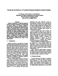
mobility by switching to different radio and antenna positions as time progresses. Thus, the emulated trajectory comprises a number of discrete steps that approximate the actual path a moving node would take as illustrated in Figure 5.
We also present a benchmark result using AODV routing in [17] that illustrates how the emulator can be used for mobile systems experiments and how noise generation can create multi-hop topologies on the testbed. IV.
SUPPORT SERVICES
In addition to the software components mentioned in previous sections, there are various support services that are used for various vital functions such as controlling node powers, serial console access to nodes, and fetching and installing images to and onto the nodes. Figure 8 summarizes the entire software architecture.
Figure 6 Spatial Switching. The path shows an actual path of a mobile node, which the system emulates by choosing the radio node that best approximates the current position. Note that at any position packets are transmitted over real radio interfaces, thus this emulator can be used to evaluate the effect of interference or other physical and link layer effects on higher layer protocols. We implement spatial switching in software using the Gigabit Ethernet connections available on the ORBIT testbed, because it allows us to scale to a large number of nodes at much lower cost than using hardware antenna switches. The software spatial switching system uses split-stack architecture, as illustrated in Fig. 7.
Figure 8 Software Architecture and Services A. Chassis Manager Controller •
•
•
The purpose of the chassis manager controller is to allow remote power on/off/reboot of the nodes. The chassis manager controller communicates the chassis manager, which is a hardware component residing on the node and is connected to the power supply. In addition to that, it provides periodic reports on the node’s health by monitoring CPU temperature, voltage levels etc. It provides serial console to the experimenters (or administrators) as a back channel to monitor and rescue nodes in case of OS crashes or other failures
Figure 7 Split-stack architecture. The network stack of a single mobile node is split between a virtual mobile node and a grid node. Throughout an experiment the application and network layer of a mobile node reside on the same machine, denoted as a virtual mobile node. As time progresses, it uses the link and physical layers of different grid nodes by reconfiguring the tunnel. The virtual mobile node can be either a dedicated grid node or a server that is on the same local area network as the grid nodes. The network stacks of the virtual mobile nodes and the grid nodes are tied together by spatial switching components. On the virtual mobile nodes, they provide a virtual network interface, fake0, which is associated with a grid node radio interface. This means that most applications can be integrated with this system by changing the routing table to point to this virtual interface.
Figure 9 Chassis Manager Controller B. Fetching and installing images to and onto nodes Since users get complete root access to the nodes during their experiment reservation, the easiest way to ensure a clean node for subsequent experiments is to fully install a new image on every node at the beginning of every experiment (at the beginning, this will be done when experiment control switches
from one organization to the other). However, in theory, it should be possible and permissible to potentially to do this before every experiment. We re-use Frisbee [18], a disk imaging application which was developed by the Emulab team [19]. Frisbee implements a secure multicast protocol to image the disk of many nodes simultaneously. Initial benchmarks have shown that it takes roughly 5-6 minutes to install image on 64 nodes simultaneously. This number is expected to stay reasonably bounded (w.r.t number of nodes) since we the underlying transport is multicast-based
conventional “flat” mesh network. We also evaluated the performance improvement obtained by using a hierarchical approach that organizes mobile nodes (MN), forwarding nodes (FN) and access points (AP) into a three-tier hierarchy. This resulted in significant improvement in the achievable capacity, coverage and QoS. The model was evaluated in terms of key performance measurements such as system throughput, average delays and packet losses for both hierarchical deployment and flat topologies
C. Noise injection using controlled interface Another important aspect of the testbed is the ability to create arbitrary topologies typically of larger dimensions onto the grid by trying to match the link characteristics of the original topology. Currently, ORBIT hardware supports injection of AWGN noise at desired power levels and center frequencies using Agilent Vector Signal Generator using distributed noise antennas positioned at appropriate positions on the grid D. Experimenters interface Currently, we use a simple mechanism for reserving time slots on the grid. This is completely Web-based as shown in the Figure below. The grid usage is in units of one hour with a maximum reservation of four hours Figure 11 Portal for Experiment Results
Figure 12 Flat vs Hierarchical topologies Figure 10 Portal for grid reservation During the time reservation, users are allowed access to the experimental controller (through VPN and SSH) and can run their experiments using scripts from command-line. We are currently working on leveraging this to allow GUI based support for experiment execution. A separate run-time and post-experiment database allows users to quickly view results during experiment run-time as well archive them for future retrievals and offline analysis as shown in the figures 11. V.
SAMPLE EXPERIMENTS USING THE TESTBED
In this section, we present a two sample experiments out of several others that we have performed on the testbed. A. System model for 802.11 based wireless mesh deployment This experiment was performed to address capacity scaling issues and performance limitations associated with
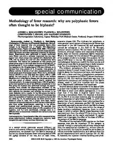
1) Experimental Evaluation In order to validate our system model, we considered a scaled area which roughly covers 0.9 sq. km having 20 users, 4 FNs and 2 APs. The two topologies were evaluated for comparison - Flat topology and a hierarchical topology as seen in Fig 12. Each run had 20 users generating increasing offered loads in steps of 0.75Mbps (from 0.75 - 3 Mbps) towards the sink (AP). These flows represented a few users who were trying to access the Internet using a gateway. We measured the total system throughput, average delays and packet loss for both the flat and hierarchical topologies under increasing offered loads. 2) Results It was observed that the hierarchical system scales to about 50 Mbps system throughput with reasonable packet delay and packet loss. This capacity of ~50 Mbps per sq-Km is sufficient to handle the traffic density in our urban coverage area scenario. By comparison, the flat ad-hoc network reaches a capacity limit at 20 Mbps and has much higher packet delay and packet loss
Figure 13 System performances (flat vs hierarchical) B. Investigate the impact of frequency diversity and PHY layer rate adaptation on the performance of 802.11 multi-hop ad-hoc networks in terms of throughput
assignments for forwarding. The end- to- end flow throughput was measured under the influence of different levels of injected noise. In the previous case using single channel, the throughput saturates at around 4.2 Mbps. In this case, however, the throughput increases up to 16 Mbps by using three different channels, a gain of ~4x for the specific flow under consideration. In the previous case, there is zero throughput at -5 dBm, where as in this case, a low throughput (~2 Mbps) can still be sustained. We believe the reason for this is that the link between 1 and 2 is completely cut off in the first case, even though the other two links are still operational
With default auto-rate adaptation and frequency diversity
1) Motivation The experiment was motivated by the fact that default 802.11-based ad-hoc networks using commercially preset autorate PHY and a single frequency channel suffer from performance degradations caused by link quality fluctuations and MAC layer self-interference respectively. A baseline adhoc network scenario was set up to determine end-to-end multihop flow throughput with default rate control and single channel operation. These results were then compared with those obtained with multiple channels and alternative PHY-rate selection methods demonstrating the potential for significant performance improvements 2) Experimental Evaluation In the baseline case, we used default auto rate adaptation implemented in the card as well as a single channel and measured the end-to-end flow throughput for a three hop network shown below, under the influence of different levels of injected noise. The offered load was increased from 2 Mbps to 8 Mbps under the influence of noise from -18 dBm to -5 dBm.
1
With default auto-rate adaptation Channel 48 Channel 48 Channel 48 2 3 4
1
Channel 36 Channel 48 2
Channel 64 3
4
Figure 15 Default auto rate with frequency diversity In the final scenario, we fixed the link rates using different combinations of PHY rate settings (R1, R2, R3) on the three links manually. Also, orthogonal channel assignments were used as before for forwarding. The end –to- end flow throughput was measured under the influence of different levels of injected noise. With fixed rate settings and frequency diversity Channel 36 1
R1
Channel 48 2
3
Channel 64 R3
4
Figure 14 Baseline case: single channel and auto rate It can be seen that the throughput saturates around 4 Mbps irrespective of the offered load as we reduce the noise power levels. At higher noise levels (in the left side of the graph), the rate fluctuation causes the overall system throughput to decrease until it finally reaches zero where one (or more) of the links is completely cut off because of the noise In this next scenario, we used default auto rate adaptation implemented in the card but used orthogonal channel
Figure 16 Fixed rate with frequency diversity Auto rate performs better than only the settings of (6, 6, 6) and (12, 6, 12). In all the other cases, up to (36, 36, 36), we see
that setting reasonably chosen fixed rates on each link performs better than auto-rate adaptation. The improvement is as large as ~3x from auto rate to the best rate selection case. This shows that auto-rate algorithm implemented on the driver/firmware is possibly too conservative because when the rate fallbacks to a lower level, it ramps up gradually thereby reducing the efficiency of the link utilization.
VIII. REFERENCES [1] [2]
[3]
VI.
CURRENT TESTBED STATUS
Recently, we extended our testbed to 400 wireless radio nodes arranged in a 20×20 grid housed in a remote facility as shown in Figure 17. The nodes are mounted off the ceiling and are separated by one meter apart. Each node has two 802.11 wireless a/b/g cards and by operating the second interface on a different channel, multi-channel forwarding can also be implemented. Every node is a small form factor PC with 1GHz VIA C3 CPU, 512 MB RAM, and 20 GB hard disk. The nodes also have two 1000BaseT Ethernet ports, which are used for control messages (such as nodeHandler commands and OML data collection). The testbed also incorporates a raw waveform generator that is connected to specifiable antennas on the grid. This generator can be remotely controlled to inject AWGN noise at a desired power level and frequency band, thereby enabling the creation of arbitrary link quality levels and related ad-hoc network topologies.
[4] [5] [6]
[7]
[8]
[9] [10] [11] [12] [13] [14]
[15] [16]
[17]
Figure 17 20× ×20 wireless grid [18]
VII. CONCLUSIONS In this paper, we presented the software design of a novel radio grid emulator testbed that is intended to facilitate a broad range of experimental research on next-generation protocols and applications. We have also explained a typical experimental lifecycle and provided sample experiments as proof-of-concept validation of the testbed design. Early enduser experiments on the ORBIT radio grid are expected to begin in the near future, and should lead to further validation and refinement of the testbed’s design. Further details on the testbed can be found on the project website [20].
[19] [20]
NSF Workshop on Network Research Testbeds,, Chicago, Il, Oct 2002, http://www net.cs.umass.edu/testbed_workshop D. Raychaudhuri, I. Seskar, M. Ott, S. Ganu, K. Ramachandran, H. Kremo, R. Siracusa, H. Liu, and M. Singh, “Overview of the ORBIT Radio Grid Testbed for Evaluation of Next-Generation Wireless Network Protocols,” Proceedings of the IEEE WCNC 2005, New Orleans, USA. http://www.orbit-lab.org Maximilian Ott, Ivan Seskar, Robert Siracusa, Manpreet Singh, "ORBIT Testbed Software Architecture: Supporting Experiments as a Service", Proceedings of IEEE Tridentcom 2005, Trento, Italy, Feb 2005 Netperf homepage, http://www.netperf.org/netperf/NetperfPage. html. RFC 1014, “XDR External Data Representation Standard, http://www.faqs.org/rfcs/rfc1014.html M. Singh, M. Ott, I. Seskar and P. Kamat, “ORBIT Measurement Framework and Library (OML): Motivations, Design, Implementation and Features”, Proceedings of IEEE Tridentcom 2005, Trento, Italy. B. Awerbuch, D. Holmer, and H. Rubens, “High Throughput Route Selection in Multi-Rate Ad Hoc Wireless Networks”, Proceedings of Wireless On Demand Network Systems (WONS 2004), pp. 251-268 Y.-C. Hu and D.B. Johnson, “Exploiting Congestion Information in Network and Higher Layer Protocols in Multihop Wireless Ad Hoc Networks”, Proceedings of International Conference on Distributed Computing Systems, ICDCS 2004, pp. 301-310. Libpcap packet capture library, http://www.tcpdump.org Libnet library, http://www.packetfactory.net/libnet/ Multiband Atheros Driver for Wifi, http://sourceforge.net/projects/madwifi/ Intel® PRO/Wireless 2200BG Driver for Linux, http:// ipw2200.sourceforge.net/ Libmac library, http://www.winlab.rutgers.edu/~kishore/ libmac_docs/ index.html J. T. Kaba and D. R. Raichle, “Testbed on a desktop: strategies and techniques to support multi-hop manet routing protocol development”, In ACM MobiHoc, pages 164–172. ACM Press, 2001. E. Hernandez and A. Helal., “RAMON: Rapid-mobility network emulator”, In IEEE LCN, Nov 2002. S. Sanghani, T.X. Brown, S. Bhandare, and S. Doshi, “ EWANT: The emulated wireless ad hoc network testbed”, In IEEE WCNC, volume 3, pages 1844–1849, Mar 2003. K. Ramachandran, S. Kaul, S. Mathur, M. Gruteser, I. Seskar, “Towards Large-Scale Mobile Network Emulation Through Spatial Switching on a Wireless Grid”, Workshop on Experimental Approaches to Wireless Network Design and Analysis (E-WIND 2005) Mike Hibler, Leigh Stoller, Jay Lepreau, Robert Ricci, and Chad Barb, “Fast, Scalable Disk Imaging with Frisbee”, USENIX 2003, June 2003. Network Emulation Testbed, http://www.emulab.net/ The ORBIT Wireless Testbed, http://www.orbit-lab.org