Architecture and Geometric Algorithms in MIRA, a Ray-based Electromagnetic Wave Simulator Sandy Sefi,
[email protected] Department of Numerical Analysis and Computer Science, Royal Institute of Technology KTH, SE:100 44 Stockholm, Sweden
Abstract In this paper we describe the basic architecture of the user-oriented electromagnetic simulator called MIRA which determines the near and far field from transmitting antennas and plane waves. The simulator is a part of the Swedish code development project GEMS: General ElectroMagnetic Solvers supported by PSCI, KTH, Saab Avionics AB, and NFFP and continues in the NFFP 473 project SMART. Keywords: Design Software, Geometrical Theory of Diffraction, Ray Tracing, Shadow Detection
1
INTRODUCTION
An electromagnetic wave simulator is used in Aerospace and Telecom areas to assist in the analysis of installed antenna performance and Radar Cross Section (RCS). Its aim is to predict the field emitted by antenna models on board large structures - buildings, aircrafts or ships - as realistically as possible. In the high-frequency band, asymptotic approximations to the Maxwell equations are suitable to evaluate the electromagnetic field. One of the powerful asymptotic methods known is the Geometrical Theory of Diffraction (GTD). The GTD [1] is based on Geometric Optics and Diffraction Theory. It assumes that all waves are “well-formed” and are locally plane waves. This enables Ray Tracing algorithms to be used with the following advantages: 1.
It supplies a method to asymptotically compute the interaction of an antenna with a structure, when classical integral formulation methods become computationally too expensive.
2.
Ray-Tracing is geometric. The computational demands is not dependent on the electrical size of the structure but only on the complexity of the geometry. There is no runtime penalty in increasing the frequency.
3.
Ray-Tracing is not memory intensive.
4.
It is relatively easy to parallelize the underlying algorithm.
MIRA is essentially a Ray-Tracer based on Fermat’s principle and works on complex CAD geometries where the objects are described by trimmed NURBS - Non Uniform Rational B-spline - and rational Bezier patches. NURBS is a standard for parametric surface representation [2]. Its Object Oriented design has been developed to support hybridization techniques with other numerical methods in the frequency domain such as Method of Moments (MoM) or Physical optics (PO). Our first hybrid application uses the Ray-Tracer module of MIRA as a stand-alone solver coupled with a PO/MoM solver [3] to determine accurately the shadow regions of the PO domain when it is illuminated by an antenna. The Method of Moments is used locally to compute the input behavior around the antenna. A similar technique is used when the wave is scattered. Below we will describe the different steps of the ray-based electromagnetic wave simulation, after that we will consider the basic features of the software architecture. Finally, we will give a brief overview of the Ray/PO hybrid.
2
THE RAY-BASED WAVE SIMULATION
The following gives a brief description of the physical process of the high-frequency wave propagation which is simulated:
Simplified Input Scene (1.)
Incident field
Trimmed NURBS
Wave Propagation
E ijIncident
Figure 1 5.
E ijReflected
2. The EM sources emit an incident field characterized by a certain direction, amplitude, phase and frequency. The field is represented by a wave. 3. The wave is absorbed, scattered, or reflected by the surfaces as it travels through the scene. The EM field is attenuated as the wave travels and the attenuation is proportional to the traveled distances.
(2.)
(3.)
1. Input of the geometry data (scene) consists of a collection of (i) surfaces in a trimmed NURBS format subdivided into a combination of Rational Bezier Patches by using the Cox De Boor algorithm [2], (ii) ElectroMagnetic (EM) sources and (iii) receivers.
E ijDiffracted
4. The wave reflected or diffracted from a surface depends on properties of the surface (curvature, transparency, surface material...) as well as on incident illumination.
High-frequency wave propagation.
The linearity of the Maxwell equations allows the superposition of the total EM field from the sum of independent electromagnetic contributions. Total Incident Reflected Diffracted E ij = E ij + E ij + E ij
Total
6.
The Total field E ij will be found as sum of the direct contributions from the source i, reflected and diffracted contributions reaching the receiver j.
7.
Each contribution is represented by rays traced from the source i to the receiver j
The determination of the rays is done following Fermat’s principle. This corresponds to tracing a ray between the source and receiver such that the optical path length reaches an extremum (maximum or minimum). The characteristic points (intersection, reflection, diffraction, etc.) are found by numerical conjugate gradient techniques applied to Fermat’s principle. This part represents the most time consuming task in the solver since the ray-path determination process requires both rational Bezier surface point evaluations and computationally expensive evaluations of derivatives on NURBS surfaces.
3
PROGRAM DESIGN AND ARCHITECTURE
To design an architecture of a computer code is the task of choosing between various available alternatives and at the same time considering possible future developments and trends. The main problem is to design an architecture that is general enough to be useful for more than a single task, while providing an appropriate framework for development and efficient implementations. In this context, our aim is to develop a code capable of performing the calculations on fully realistic industrial models, to easily support future requirements or functionalities and to allow hybridization with other computational electromagnetic tools. HISTORY AND BACKGROUND The starting point for the architecture of MIRA was the FASANT code which was developed at Cantabria University by F. Cátedra and co-workers. From a computational electromagnetic point of view, this is a good old - quite reliable - code. Its functionalities and comparison with measurements can be found in [4]. A good comparison with the NEC/BSC code can be found in [5]. Apart from possessing these qualities, we found the Fortran 77 FASANT code difficult to modify and we decided to redesign the code by going back to the fundamental theory [6] and do a complete re-implementation using object oriented design with a Fortran 90 implementation. However, it is important to remark here that in the course of redesigning FASANT, we also introduced new algorithms. For example, we added diffraction algorithms, based on a search of combinations of local minima and local maxima, diffraction corner detection, double diffraction path determination, better visibility preprocessing taking into account transparent surfaces or dielectric sheets, etc.... The results and the description of the new features can be found in [7]. FEATURES OF THE ACTUAL ARCHITECTURE The following design features were leading up to a wave simulator architecture powerful and flexible enough to support hybrid applications: 1.
Modular design
This work follows ideas from the Computer Graphics Society in the area of physical rendering processes [8]. These ideas [9] stipulate that a modular design should permit (i) the same general architecture to be configured for use in various application areas, (ii) the development of new algorithms and (iii) the implementation of variations of existing techniques reusing the already available environment. To fulfill it in our context, we have structured the architecture by a clear division of the complete system into subsystems called modules. The different modules have to be as independent of each other as possible and require well defined interfaces between them. The interfaces must be general enough not to limit the range of possible implementations. One major obstacle on this
theme are dependencies between modules, which need to be minimized. The details of this modular approach can be found in [10].
Object Orientation
Other Modular Solver
Classes inheritance
HYBRID CODE
e rat cu
Flexibility switch
Ac
Fa
st
Limited modules dependencies
Software with Modular Design Figure 2 2.
Features of the software architecture
Object orientation.
Each object (3D surfaces, bounding curves, rays, antennas...) has well-defined interfaces consisting of a set of operations or methods that may be invoked by other objects. It also has internal attributes that represent the state of the object. The set of methods and attribute variables is described by the class of the object. Classes are manually organized in inheritance since automatic inheritance is not supported by Fortran 90 language. A class inherits behavior and attributes from its parents. In this way, the internal state of an object is encapsulated by the interface and can be manipulated by other objects only through the methods offered. This permits a clear separation between the interface of an object and its implementation. It defers the handling of implementation details from the early stages of the analysis and design process and therefore allows for better abstraction. 3.
Good accuracy
The accuracy is only limited by the algorithms used and the parameters chosen, but not by the architecture itself. Since accuracy most often is coupled with the computational cost of the calculations, the architecture allows various options for trading accuracy against computational complexity. One way to offer this is to allow for different solution strategies for various parts of the system (c.f. flexibility). The generic characteristics of the new structure permit the coexistence of different geometrical representation. For instance, the initial free-formed surfaces (NURBS, rational Bezier etc....) coexist with the set of the plane facets/triangles constructing the mesh. Each surface is labeled and each
facet/triangle knows on which surface it belongs. All these links between data represent an important step toward improving the accuracy. In fact, the solver will work faster with only a facet description but will need to go back to geometrical information for tangents, radius of curvature, etc., to make precise field calculations. 4.
Flexibility
Flexibility generally comes at a cost. In most cases a specific interface can be implemented with better performance than a general interface. In each case we have to decide if the additional flexibility is worth the price imposed by it or if a restricted interface offers substantially better performance. Sometimes, this might require the implementation of both the general interface and an interface with better performance but restricted functionality. We believe that in many cases and in the long run it is more important to provide a flexible interface than the implementation with the highest performance. 5.
Handling of complex models
To be useful for real world applications an architecture must handle large and complex data sets. A fully realistic model is typically composed by more than one thousand NURBS surfaces. This requires the minimization of the storage requirements within the architecture. Practically, for the representation of the geometry data structure, linked chains of buffers dynamically allocated are preferred to one huge list of surfaces stored in a fixed sized matrix. 6.
Modern programing style
Good coding allows for more efficient research and development. Current coding practices are in strict opposition to old fashion programming style characterized by “goto” loops, code duplication instead of subroutine calls and global variables used in many different parts of the code. Instead we assist on variable names that mean something, parentheses and white-space to make the code readable. 7.
Robust design
We have significantly improved code quality and reliability thanks to systematic checking of input arguments, parameters and tolerances, division by zero etc.... 8.
Efficiency thanks to topological information
The topology of an object is the list of the connections between faces (surfaces), edges (bounding curves) and vertices (corners) of a geometrical object. Most recent CAD products include topological facilities. A remaining problem is that engineers are used to exchanging data using IGES1 formats likes which do not transfer the topology [11]. In this context, we were faced with the task of extracting the necessary topological information directly from the geometry. The topology is used to improve the global efficiency of the computations. For instance, when examining diffraction phenomena, the topology permits the following edge classification: an edge can be (i) free: a boundary without neighboring surface, (ii) C0: continuity everywhere between neighboring surfaces, (iii) C1: not the same tangent plane for two surfaces or (iv) material discontinuity. This classification permits the removal of fictitious edges and speeds up the diffraction localization search [12] by directly focusing on the correct edge (C1). Edges are defined as Bezier curves. The classification is obtained from the study of normal discontinuities at the boundary curves between NURBS. The topology is pre-computed in a table. The table contains labeled information such as parentship relations with the surfaces and neighboring edge relations.
1
IGES, the Initial Graphics Exchange Specification, is a widely used CAD data exchange specification.
9.
Performance
Maybe the most important factor is to obtain acceptable performance. The Ray tracer does this by using simple algorithms, avoiding redundant calculation and unnecessary computations. For example, the measured execution time of the determination of the direct illumination for 100.000 rays launched through a scene composed of 400 NURBS surfaces, is less than 3 minutes on one node of an IBM RS6000 with 160 MHz, 256 MB of RAM. For comparison, on a very small example of a direct near field and diffraction calculation at six receivers illuminated from one source around a cylinder (only 6 NURBS), FASANT gets 0.37 Mflops (Million floating-point operations per second) for a total execution time (wall clock time) of 97,7 seconds. On the same problem, MIRA runs at 5.16 Mflops during a total execution time of 6.5 seconds, which makes it 15 times faster than FASANT. These results differ so much since we are using a new detection of diffraction path based on direct search of local minima and maxima (Fermat’s principle) instead of running a minima search and use an algorithm for discarding false solution. In addition this results also illustrates how important the topology can be to improve the code performance.
4
HYBRIDIZATION: SHADOW DETERMINATION
The coupling of the Ray Tracer module of the wave simulator to a PO solver reuses the ray module to determine accurately the parts of the non illuminated PO domain situated in the shadow regions of an emitting source. The hybridization improves the PO approximation by removing from the study all the geometrical details residing inside the shadow cast by a PO object on itself (self shadow) or by any blocker (other eventual object) between the PO domain and the emitting source (occlusion). THE HYBRID ALGORITHM To solve this problem, a test ray is launched from the barycenter of each PO facet/triangle. The ray is then traced back toward the point source. If the ray path to the source is not blocked by other surfaces, then the facet is directly illuminated, the surface current distribution is computed with J = 2nxH . A PO approximation of the scattered field can be obtained from the surface current J by integrating the PO fields and finally compute the RCS of the object under study. In our first version, only the incident field is used to illuminate (no reflection nor diffraction). This task remains however highly time consuming since a huge number of rays has to be traced. In the future, indirect illumination of the PO domain coming from the reflection of a ray on a surface, can easily be added. The two main characteristics of this algorithm are: 1.
High computational complexity. There are (i x j) occlusion tests to perform. During one occlusion, several intersection tests must be executed with all the surfaces facing the points i or j. Each intersection test requires heavy NURBS derivations and surface point evaluations.
2.
The independency of computations between each source i and receiver j gives natural parallelization.The details of the parallelization realized with MPI library calls and implemented on the IBM SP with Power2 processors can be found in [13].
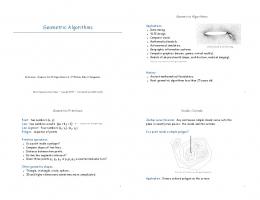
ILLUSTRATION For the assumptions and algorithm presented above, the current distribution on a realistic aircraft is obtained. The tested geometries are realistic industrial models and have been
borrowed from Saab Avionics. The geometry is composed by 82.736 triangles/receivers that facetize 368 trimmed NURBS surfaces. Figure 3 represents the current distribution without taking into account the occlusion (this picture is given as reference to illustrate the PO solver working by its own). Figure 4 represents the illumination taking into account self shadow and occlusion. A single source, a plane wave perpendicular to the nose of the plane, illuminates 82.000 receivers placed on the aircraft surface.
Figure 3 PO only without Ray-tracing: current surface distribution on an aircraft from a plane wave pointing vector parallel to the aircraft center axis.
Figure 4 PO and shadow: illumination taking into account the self shadow of the aircraft. The dots represent triangles illuminated by a plane wave. In such orientation, half of the wing surfaces are occluded.
5
CONCLUSION
In this paper we have proposed an architectural approach to the implementation of an high frequency electromagnetic wave simulator. Its Object Oriented design is powerful and flexible enough to support a number of algorithms, yet can handle large and complex bodies. It has been developed to support hybridization techniques. In particular, we have given a detailed description of our recent Ray/PO hybrid. The method described combines several new concepts: use of topological information, double geometry representation: NURBS & Triangulation and accurate shadow detection taking into account self occlusion to a powerful Applied Electromagnetics software. Future improvements will focus on efficiency aspects for industrial applications.
References [1]
J. B. Keller, “Geometrical Theory of Diffraction”, J. of Optical Soc. of Americ., Vol. 52, No. 2, pp. 116-130, February, 1962.
[2]
Gerald Farin, “Curves and Surfaces for Computer Aided Geometric Design”, Fourth Edition, Acad. Press, 1996.
[3]
Johan Edlund, Stefan Hagdahl and Bo Strand, “An investigation of hybrid techniques for scattering problems on distinct geometries”, Technical Report PSCI No. 2000:08, KTH, March, 2000.
[4]
J. Pérez, F. Saiz, J., O. Gutierrez, I. Gonzalez, M.F. Cátedra, I. Montiel, J. Guzmán, “FASANT: Fast Computer Tool for the Analysis of Antennas OnBoard Antennas”, IEEE Antennas and Propagation Magazine, Vol. 41, No. 2, June, 1999.
[5]
J. Pérez, J.A. Saiz, O. Conde, R.P. Torres, M.F. Cátedra, “Analysis of Antennas on Board Arbitrary Structures Modelled by NURBS Surfaces”, IEEE Transactions on Antennas and Propagation, Vol. 45, No. 6, June, 1997.
[6]
M.F. Cátedra et. al., “FASANT (Version S.4) Theoretical Foundations”, Technical report, Signal Theory and Comm. Dept., Univ. of Alcalá, 1998.
[7]
Sandy Sefi, “Design and Architecture of MIRA, a Ray-based Electromagnetic Code”, DRT’s thesis, University Joseph Fourier, Grenoble, France, October 2000.
[8]
Philipp Slusallek, Hans-Peter Seidel, “Vision: An architecture for global illumination calculations”, IEEE Transactions on Visualization and Computer Graphics, 1(1):77--96, March, 1995.
[9]
Philipp Slusallek, “Vision - An Architecture for Physically Based Rendering”, PhD thesis, University of Erlangen, IMMD IX, Computer Graphics Group, April, 1995.
[10]
Fredrik Bergholm, Stefan Hagdahl, Sandy Sefi, “A modular Approach to GTD in the Context of Solving Large Hybrid Problems”, proceeding publication in AP2000 Millennium Conference on Antennas & Propagation, Davos, Switzerland, April, 2000.
[11]
Patrick Chenin, “Geometric Modelling for ElectroMagnetic Simulation”, LMC-IMAG Unival S.A., August 1998.
[12]
Fredrik Bergholm, “Locating Diffraction Points with Ray-based Methods”, Technical Report PSCI, KTH, December, 2000.
[13]
Sandy Sefi, “Parallelization of a Ray-based Electromagnetic Wave Simulator using MPI”, PDC High Performing Computing Course Report, KTH, August, 2001.