provide the architectural flexibility needed to meet the changing business requirements of the ...... Maintainability â the ability to repair the software or hardware.
Architecture– Architecture–Centered Information Systems in the Manufacturing Domain Architecture is the semantic bridge between the requirements and software. The use of an architecture–centered development process for delivering information technology began with the introduction of client / server based systems. Early client/server and legacy mainframe applications did not provide the architectural flexibility needed to meet the changing business requirements of the modern manufacturing organization. With the introduction of Object Oriented systems, the need for an architecture– centered process became a critical success factor. Object reuse, layered system components, data abstraction, web based user interfaces, CORBA, and rapid development and deployment processes all provide economic incentives for object technologies. However, adopting the latest object oriented technology, without an adequate understanding of how this technology fits a specific architecture, risks the creation of an instant legacy system. Application software systems must be architected in order to deal with the current and future needs of the business organization. Managing software projects using architecture–centered methodologies must be an intentional step in the process of deploying information systems – not an accidental by–product of the software acquisition and integration process.
Glen B. Alleman Niwot, Colorado 80503 Copyright © 2000, 2001, 2002 All Rights Reserved
INTRODUCTION .................................................................................................. 1 W HAT IS SOFTWARE ARCHITECTURE?................................................................... 1 ARCHITECTURE BASED IT STRATEGIES ................................................................. 2 INFORMATION SYSTEMS IN MANUFACTURING .......................................................... 4 CHARACTERISTICS OF MANUFACTURING TECHNOLOGIES .......................................... 4 MOTIVATIONS FOR ARCHITECTURE–C ENTERED D ESIGN ........................................... 5 Architectural Principles............................................................................... 5 Architectural Styles .................................................................................... 6 4 + 1 ARCHITECTURE ........................................................................................ 7 MOVING FROM 4+1 ARCHITECTURE TO M ETHODOLOGIES ......................................... 9 STRUCTURE MATTERS ..................................................................................... 10 THE ARCHITECTURE PROCESS ....................................................................... 11 THE METHODOLOGY AND 4 + 1.......................................................................... 12 Methodology and the Architecture............................................................. 13 Methodology for the SRA ......................................................................... 14 Methodology for the TSD ......................................................................... 16 STEPS IN THE ARCHITECTURE PROCESS........................................................ 17 THE VISION OF THE SYSTEM .............................................................................. 18 BUSINESS CASE ANALYSIS ................................................................................ 18 REQUIREMENTS ANALYSIS ................................................................................ 18 4 + 1 and UML ........................................................................................ 20 ARCHITECTURE PLANNING ................................................................................ 20 Enterprise Viewpoint ................................................................................ 21 Information Viewpoint .............................................................................. 22 Computational Viewpoint.......................................................................... 23 Engineering Viewpoint ............................................................................. 23 Technology Viewpoint .............................................................................. 24 PROTOTYPING THE SYSTEM .............................................................................. 24 Building Block Based Development ........................................................... 24 Building Blocks of the Prototype................................................................ 25 MANAGING THE PROJECT ................................................................................. 26 PROTOTYPING THE ARCHITECTURE..................................................................... 27 INCREMENTAL DEPLOYMENT OF THE SYSTEM ....................................................... 28 TRANSITIONING THE SYSTEM TO P RODUCTION ...................................................... 28 OPERATING AND MAINTAINING THE SYSTEM ......................................................... 28 CONTINUOUS M IGRATION OF THE SYSTEM COMPONENTS ....................................... 29 APPLYING THE METHODOLOGY ....................................................................... 31 THE ROLE OF THE ARCHITECT ........................................................................... 31 ARCHITECTURE MANAGEMENT ........................................................................... 31 Architecture Evaluation ............................................................................ 32 Architecture Management ........................................................................ 32 System Design Process........................................................................... 33 Non–Functional Architecture .................................................................... 35 APPLYING THESE P RINCIPLES ............................................................................ 35 AN EXAMPLE A RCHITECTURE ............................................................................ 36 REFERENCES ................................................................................................... 39 END NOTES ...................................................................................................... 45
INTRODUCTION The subject of the integration of heterogeneous manufacturing systems is not only complex it is convoluted and confusing. By focusing on the architecture of the system, the design and development processes have a place to return to when this situation occurs.
Much of the discussion in today’s literature is centered around the building architectural analogies to the design and deployment of [1] information systems. This analogy glosses over many of the difficulties involved in formulating, defining, and maintaining the architectural consistency associated with acquiring and integrating Commercial Off The Shelf (COTS) applications. The successful deployment of a COTS based system requires that not only are the current business needs met, but that the foundation of the future needs of the organization be laid. In many COTS products, the vendor has defined an architecture that may or may not match the architecture of the purchaser’s domain. It is unlikely the vendor’s architecture will be a match for an organization that has mature business processes and legacy systems in place. The result [2] is an over–constrained problem. The consequences of this purchasing decision may not be known for some time. If the differences between the target architecture of the business and the architecture supplied by the vendor are not determined before the acquisition these gaps will be revealed during the systems operation – much to the disappointment of the purchaser. W HAT IS S OFTWARE A RCHITECTURE?
The term architecture is so overused in the software business, that it has become a cliché. There are “official” descriptions of software architecture and architects. Much of the architecture work has taken place inside development organizations and academia. In this paper, the description of architecture is taken from a variety of reliable sources.
Software architecture can be defined as the generation of the plans for information systems, analogous to the plans for an urban dwelling space. Christopher Alexander [Alex77], [Alex79] observed that macro– level architecture is made up of many repeated design patterns. [3] Software architecture is different from software design in that software architecture is a view of the system as a whole rather than a collection of components assembled into a system. This holistic view forms the basis of the architecture–centered approach to information systems. Architecture becomes the planning process that defines the foundation for the information system. Distributed object computing and the Internet have fundamentally changed the traditional methods of architecting information systems. The consequences of these changes are not yet fully understood by the developers as well as consumers of these systems. The current distributed computing (client/server) and Internet–based systems are complex, vulnerable, and failure–prone when compared to the mainframe predecessors . This complexity is the unavoidable consequence of the demand for ever–increasing flexibility and adaptability. These rapidly changing technologies require a different planning mechanism for deployment, one based on fundamentally new principles. Because technology is rapidly changing and business requirements are more demanding, a process for architecting these new systems is now essential. No longer can systems be simply assembled from components without consideration of the whole [Foot97]. Architecture is not the creation of boxes, circles, and lines, laid out in slide presentation [Shaw96], [Shaw96a]. Architecture imposes decisions
Copyright ©, January 2002
1
and constraints on the process of designing, developing, and deploying information systems. [Adow95], [Alle94], [Kazm96], [Perr92]. Architecture must define the parts, the essential external characteristics of each part, and the relationships between these parts in with the goal of assuring a viable outcome.
Architecture is the set of decisions about any system that keeps its implementers and maintainers from exercising needless creativity. The architecture of a system consists of the structure(s) of its parts, the nature and relevant externally visible properties of those parts, and the relationships and constraints between them [D’Sou99].
A R C H I T E C T U R E B A S E D I T S TRA T E G I E S Much has been written about software and system architecture [Sei00]. But the question remains, what is architecture and why is it important to the design and deployment of software applications in the manufacturing domain? Manufacturing information systems possess a unique set of requirements, which are continuously increasing in complexity. In the past, it was acceptable to provide manufacturing information on a periodic basis. This information was gathered through a data entry process that was labor intensive and error prone. In the current manufacturing environment, the timeliness and accuracy of information [4] has become a critical success factor in the overall business process. In the past, manufacturing information was usually provided through a [5] monolithic set of applications (mainframe based MRP systems). This critical data was trapped inside the applications, which were originally designed to liberate the workforce from mundane data processing tasks [Bryn98], [Bryn93]. However, without flexibility and adaptability, the users were forced to adapt their behaviors to the behaviors of the system. The result was a recurring unrecoverable cost burden on the organization. What was originally the responsibility of the software – as defined in the Systems Requirements Analysis – becomes the burden of the user [Bryn98], [Schr97], [Bryn96]. In the manufacturing environment, this includes multiple and inconsistent data entry tasks, report printing and reentry, inconsistent database information, islands of information and automation, and the inability to adapt to the changing needs of the organization. The approach of scheduling multi–product batch production activities using an MRP system has given way to customer driven massive customization production with just–in–time everything [Maho97]. It also has become more difficult to predict customer demand for configured
Copyright ©, January 2002
2
products. This adds to the complex problem of manufacturing, planning, and production scheduling. Any replacement of the legacy manufacturing system that currently supports batch production must provide: n
Support for manufacturing processes that can be quickly modified and expanded as production demand changes.
n
A mechanism to address the previously well–defined boundary between product produc tion, product design, and business and financial management.
n
A migration path away from the traditional product bills–of–material approach to production scheduling. This previous approach has given way to configured bills–of–material, generated at the time the order is taken, supported by just–in–time component suppliers.
An effective manufacturing system architecture must somehow combine [6] production control systems and information systems. Most approaches in the past elected to keep these two systems separate but linked, adapting them to make intersystem communication transparent. However, this strategy fails to address the important problem of how to restructure the manufacturing operations to meet the demand of future operations. An alternative approach is to integrate the Manufacturing Control System (MCS) with the Manufacturing Information System (MIS) as a federated heterogeneous system. Production personnel can then make use of the MIS maintained information (design and product information) directly on the shop floor. In turn, design and support personnel can then gain direct access to production information. The complexity of this massive customization and just–in–time manufacturing environment means that the software components, and the work processes they support, are in constant flux. For an integrated manufacturing system to function in this way, software systems must be continuously expanded, modified, revised, tested, and repaired. The software components must be integrated quickly and reliably in response to rapidly changing requirements. Finally, such a system must cooperate in addressing these changing objectives. All these requirements define a highly flexible, adaptive architecture capable of operating in rapidly changing conditions [Mori98]. In order to address these needs, the system architecture can proceed along the following path: n
Define the goals of the business in a clear and concise manner.
n
Identify existing Information Technology that meets these goals.
n
Identify gaps in the Information Technology that fail to meet these goals.
n
Identify the organizational structure needed to support the the strategy.
Copyright ©, January 2002
3
n
Define a layered framework for connecting the system components.
I NFORMATION SYSTEMS IN MANUFACTURING In the traditional information systems domain the operational improvements of the shop floor are the primary focus of IT. By expanding the scope of the IT Strategy to include all aspects of manufacturing, from order entry to product shipment, an overall architecture of the information systems can be constructed.
Although much of this paper is targeted at generic systems architecture, it is useful to outline the manufacturing systems that are subject to these architectural constraints. n
Operations Improvement – the operational information systems provide the tools needed to run the business on a day–by–day basis. They provide real time information about costs, productivity, and operational efficiency. They include information, work planning and operational control for: n
Materials management
n
Flexible manufacturing
n
Machine tool control
n
Automated process control
n
Advanced Manufacturing Technologies – the control of machinery through automated work instructions, machine tool instructions, and other non–human intervention processes that contribute directly to the bottom line of the business.
n
Information Systems – the application software that forms the basis of the operational efficiency and advanced machine control, is dependent on the order entry, production scheduling and shop floor control facilities provided by: n
ERP – enterprise resource planning. Is an accounting oriented information system for identifying and planning enterprise wide resources needed to take, make, ship, and account for customer orders.
n
PDM – product data management. Is a collection of applications that maintain the logical and physical relationships between the various components of a product.
n
Product Configuration – provides the management of the configuration processes. a Configurator provides knowledge based rules and constraints for assembling parts into products or systems to be delivered against a customer order.
n
EDM – enterprise document management. Is an infrastructure system, which document–enables business process and application through workflow and a document repository. The primary function of EDM is to manage the change to business critical documents and delivery these document to the proper user at the proper time.
C HARACTERISTICS OF MANUFACTURING T ECHNOLOGIES There are several characteristics of manufacturing systems that are shared by all systems with good architectural foundations. [Witt94], [Rech97], [Shaw96], [Garl95] These properties may appear abstract and not very useful at first. However, they are measurable attributes of a
Copyright ©, January 2002
4
system that can be used to evaluate how well the architecture meets the needs of the user community. n
Openness – enables portability and internetworking between components of the system.
n
Integration – incorporates various systems and resources into a whole without ad–hoc development.
n
Flexibility – supports a system evolution, including the existence and continued operation of legacy systems.
n
Modularity – the parts of a system are autonomous but interrelated. This property forms for the foundation of flexibility.
n
Federation – combining systems from different administrative or technical domains to achieve a single objective.
n
Manageability – monitoring, controlling, and managing a system’s resources in order to support configuration, Quality of Service (QoS), and accounting policies.
n
Security – ensures that the system’s facilities and data are protec ted against authorized access.
n
Transparency – masks from the applications the details of how the system works.
M OTIVATIONS FOR A RCHITECTURE– C ENTERED D ESIGN The manufacturing domain creates a unique set of requirements, not found in other business information system environments. By focusing on the non-functional requirements for manufacturing systems, the operational aspects of the software can be isolated from the underlying infrastructure. This isolation provides the means to move the system forward through its evolutionary lifecycle, while minimizing the impacts on the operational aspects of the business processes.
The application of architecture–centered design to manufacturing systems makes several assumptions about the underlying software and its environment: n
Large systems need sound architecture. As the system grows in complexity and size, the need for a strong architectural foundation grows as well.
n
Software architecture deals with abstraction, decomposition and composition, style, and aesthetics. With complex heterogeneous systems, the management of the system’s architecture provides the means for controlling this complexity is a critical success factor for any system deployment.
n
Software architecture deals with the design and implementation of systems at the highest level. Postponing the detailed programming and hardware decisions until the architectural foundations are laid is a critical success factor in any system deployment.
Architectural Principles Software architecture is more of an art than a science. This paper does not attempt to present the subject of software architecture in any depth, since the literature is rich with software architecture material [Tanu98],
Copyright ©, January 2002
5
[Witt94], [Zach87], [Shaw97], [Hofm97], [Gunn98], [Sei00]. There are several fundamental principles however to hold in mind: n
Abstraction / Simplicity – simplicity is the most important architectural quality. Simplicity is the visible characteristic of a software architecture that has successfully managed system complexity
n
Interoperability – is the ability to change functionality and interpretable data between two software entities. Interoperability is defined by four enabling requirements: [7]
n
n
Communication Channel – the mechanisms used to communicate between the system components.
n
Request Generation Verbs – used in the communication process.
n
Data Format Nouns – the syntax used for the nouns.
n
Semantics – the intended meaning of the verbs and nouns.
Extensibility – is the characteristic of architecture that supports unforeseen uses and adapts to new requirements. Extensibility is a very important property for long life cycle architectures where changing requirements will be applied to the system. Interoperability and extensibility are sometimes conflicting requirements. Interoperability requires constrained relationships between the software entities, which provides guarantees of mutual compatibility. A flexible relationship is necessary for extensibility, which allows the system to be easily extended into areas of incompatibility.
n
Symmetry – is essential for achieving component interchange and reconfigurability. Symmetry is the practice of using a common interface for a wide range of software components. It can be realized as a common interface implemented by all subsystems or as a common base class with specializations for each subsystem.
n
Component Isolation – is the architectural principle that limits the scope of changes as the system evolves. Component isolation means that a change in one subsystem will not require a change in another.
n
Metadata – is self–descriptive information, which can describe services, and information. Metadata is essential for reconfigurability. With Metadata, new services can be added to a system and discovered at runtime.
n
Separation of Hierarchies – good software architecture provides a stable basis for components and system integration. By separating the architecture into pieces, the stability of the whole may sometimes be enhanced.
Architectural Styles Architectural style in software is analogous to an architectural style in buildings. An architectural style defines a family of systems or system components in terms of their structural organization. An architectural
Copyright ©, January 2002
6
style expresses components and relationships between these components, with constraints on their application, their associated composition, and the design rules for their construction [Perr92], [Shaw96], [Garl94]. Architectural style is determined by: n
The component types that perform some function at runtime (e.g. a data repository, a process, or a procedure).
n
The topological description of these components indicating their runtime interrelationships (e.g. a repository hosted by a SQL database, processes running on middleware, and procedures created through user interaction with a graphic interface).
n
The semantic constraints that will restrict the system behavior (e.g. a data repository is not allowed to change the values stored in it).
n
The connectors that mediate communication, coordination, or cooperation among the components (e.g. protocols, interface standards, and common libraries).
There are several broad architectural styles in use in modern distributed systems and several detailed substyles within each broad grouping [Shaw96], [Abow95]. Because practical systems are not constructed from one style, but from a mixture of styles, it is important to understand the interrelationship between styles and their affect on system behavior. This architectural style analysis [Adow93]: n
Brings out significant differences that affect the suitability of a style for various tasks, the architect is empowered to make selections that are more informed.
n
Shows which styles are variations of others, the architect can be more confident in choosing appropriate combinations of styles.
n
Allows the features used to classify styles to help the designer focus on important design and integration issues by providing a checklist of topics.
4 + 1 AR C H I T E C T U R E There are many architectural paradigms in the market place. The 4+1 paradigm is used here to focus the system architecture of the decomposition of the architectural components into a COTS based view of the system.
In many projects, a single diagram is presented to capture the essence of the system architecture. Looking carefully at the boxes and lines in these diagrams, the reader is not sure of the meaning of the components. Do the boxes represent computers? Blocks of executing code? Application interfaces? Business processes? Or just logical groupings of functionality? [Shaw96a]
Copyright ©, January 2002
7
One approach to managing architectural style is to partition the architecture into multiple views based on the work of [Kruc95], [Adow93], [Perr92], [Witt94]. The 4+1 Architecture describes the relationship between the four views of the architecture and the Use [8] Cases that connect them. A view is nothing more than a projection of the system description, producing a specific perspective on the system’s components. Developer / Integrator
End User
Logical Architecture
Development Architecture
System Usage Scenarios
Process Architecture
Abilities
Use Cases
Physical Architecture
System Engineers
Figure 1 – The 4+1 Architecture as Defined by [Kruc95]
Figure 1 describes the 4+1 architecture as defined in [Kruc95]. The 4+1 architecture is focused on the development of systems rather than the assembly of COTS based solutions. The 4+1 paradigm will be further developed during the ARCHITECTURAL PLANNING phase using the ISO/IEC 10746 guidelines.
Copyright ©, January 2002
8
The system architecture is the structure of a software system. It is described as a set of software components and the relationships between them. For a complete description of an architecture several views are needed, each describing a different set of structured aspects [Hofm97].
For the moment, the 4+1 Architecture provides the following views: n
Logical – the functional requirements of the system as seen by the user.
n
Process – the non–functional requirements of the system described as abilities.
n
Development – the organization of the software components and the teams that assemble them.
n
Physical – the system’s infrastructure and components that make use of this infrastructure.
n
Scenarios – the Use Cases that describe the sequence of actions between the system and its environment or between the internal objects involved in a particular execution of the system.
There are numerous techniques used to describe the architectural views of a system: algebraic specifications [Wirs90], entity relationship diagrams [Chen76], automata [Hopc90], class diagrams [Rumb91], message sequence diagrams [ITU94], data flow diagrams [DeMarc79], as well as many others. In this paper, the Unified Modeling Language (UML) combines many of these notations and concepts into a coherent notation and semantics [Booc99], [Fowl97], [D’Sou99]. M O V I N G F R O M 4 + 1 AR C H I T E C T U R E T O M E T H O D O L O G I E S Now that the various components of system architecture are established, the development of these four architectural components must be placed within a specific context. This is the role of an architectural methodology. In the 4+1 architecture the arrangements of the system components are described in constructive terms – what are the components made of. The next step in the process is to introduce a business requirements architecture process. The business requirements will drive the architecture. Without consideration for these business requirements the architecture of the system, would be context free. By introducing the business requirements, the architecture can be made practical in the context of the business and therefore become it can become generative. These business requirements are not the business functions, but rather the functional and non–functional requirements of a system to support the business functions.
Copyright ©, January 2002
9
S TRUCTURE M ATTERS From the beginnings of software engineering, structure has been the foundation of good architecture [Parn72], [Dijk68]. There are some basic tenets that can be used to guide the architecture–centered deployment [Clem96]: n
Systems can be built in a rapid, cost–effective manner by importing (or generating) large externally developed components.
n
It is possible to predict certain qualities about a system by studying its architecture, even in the absence of detailed design documents.
n
Enterprise–wide systems can be deployed by sharing a common architecture. Large–scale reuse is possible through architectural level planning.
n
The functionality of a system component can be separated from the component’s interconnection mechanisms. Separating data and process is a critical success factor for any well architected system
———
Copyright ©, January 2002
10
THE ARCHITECTURE PRO CESS The selection of a specific methodology for capturing, defining, and describing the system architecture is an arbitrary decision. The following methodology is used as an example. Other methodologies can be used as long a they provide a sufficiently rich set of artifacts needed to articulate the requirements and the solutions that meet those requirements.
Figure 2 describes the process by which the architecture of the system is discovered, verified, and deployed. This view may be criticized as a waterfall approach. In fact, it is sequential at the macro–level, with overlapping activities. This methodology is a macro–model for the system. At this level the rapid development, eXtreme Programming, iterative development programming methods are just that – programming methods. They are not system architecture methods. This methodology provides a broad framework in which systems architecture can be put to work. Depending on the specific needs of the organization, each methodology phase may be adapted to the desired outcome. In some situations, the business case and IT Strategy already exist and the technical aspects of the system dominate the effort. In other situations, the framework for thinking about the problem must first be constructed before any actual system construction can take place. The methodology provides guidelines without overly constraining the solution domain. The methodology is vendor neutral, notation neutral and adaptive to the organization’s short and long–term needs. The methodology has been proven in the field, in a wide variety of manufacturing industry environments, ranging from petrochemicals to discrete parts manufacturing.
System Strategy Requirements Analysis
Initial Study
Technical System Design
Deployment Specification
Business Case
Non–Functional Requirements
Business Requirements
Capabilities
Compliance
Vendor
Figure 2 – The Methodology steps for Architecture Development
Copyright ©, January 2002
11
T HE M E T H O D O L O G Y A N D 4 + 1 The primary components of the methodology focused on the 4 + 1 Architecture are shown in Figure 3. This methodology is deployed in the context of: n
Commercial off the shelf (COTS) – products integrated into a federated system. The external functionality of a COTS product is defined by the vendor. The behavior of the system is usually fixed in some way, with little or no ability to alter the internal functioning. External behaviors can sometimes be tailored to meet business needs, within the framework of the COTS product.
n
Line of Business databases – used to separate the data from the applications. Legacy applications hold information within their boundaries that must be integrated with the new system. In many instances, it is not feasible to move this legacy data to a new system.
n
Workflow engines – used to manage the business processes. In many environments the work processes are fluid, changing with the business climate. Adapting the work processes to the business process is usually done through some form of workflow
Using this context, the traditional software development approach to system architecture is not appropriate. Writing software in the COTS environment is a rare occurrence. The 4 + 1 architecture is adapted to describe the behavioral and best practice attributes of the system. In the COTS domain, the 4 + 1 Architecture descriptions are now: n
Logical – the functional requirements of the business process that are directly implemented by the system. These include any manual processes or custom components that must be provided to work around gaps in the COTS system.
n
Process – the abilities of the system that are required to meet the business requirements.
n
Development – the vendor, system integrator, business process, and management teams and resources needed to define, acquire, install, deploy, operate the system.
n
Physical – the infrastructure needed to define, acquire, install, deploy, and operate the system.
n
Scenarios – the Use Cases that describe the sequence of actions between the system and its environment or between the external objects involved in a particular execution of the system.
The design of software systems involves a number of disciplines applied during the various phases of the methodology. In the past, functional decomposition and data modeling was the accepted mechanism for defining the system architecture. The descriptive and generative [9] aspects of these notations have given way to UML based notations. Although the methodology described here is technically independent of
Copyright ©, January 2002
12
any notation or requirements methodology style, there are advantages to using the current state–of–the–art tools. These include: n
Providing reassurance through graphical descriptions of the system. Using a layered descriptive language, pictures of the system can be constructed at all levels of detail — from high level executive diagrams to programmer's level details of data and processes.
n
Providing generative descriptions, which transform functional decompositions into code templates.
n
Strong textual descriptions, since pictures alone are rarely sufficient to convey the meaning of design.
n
Aesthetic renditions that convey good design principles through a simple, clear, and concise notation.
Methodology and the Architecture Figure 3 presents a rearranged topology for the methodology. This arrangement focuses on applying the architectural principles to the components of the methodology. There are steps in the methodology that are not addressed in Figure 3. Although these steps may be impacted by architecture they are secondary to the Requirements Analysis, Technical System Design, System Development, and System Deployment.
Copyright ©, January 2002
13
Project Management Continuous Migration Ops and Maint Transition Incremental Development Prototype
Requirements Analysis
Initial Study
Functional Ÿ Ÿ Ÿ Ÿ Ÿ Ÿ Ÿ Ÿ Ÿ Ÿ Ÿ
Abstraction Encapsulation Information Hiding Modularization Separation Coupling Sufficiency, completeness and primitiveness Separation of policy and implementation Separation of interface and implementation Single point references Divide and Conquer
Technical System Design
System Development
System Deployment
Enterprise View Information View Computational View Engineering View Technology View
Non Functional Ÿ Ÿ Ÿ Ÿ Ÿ Ÿ
Changability Interoperability Efficiency Reliability Testability Reusability
Figure 3 – Details of the methodology and its relationship to system architecture.
Methodology for the SRA The System Requirements Analysis (SRA) includes the discovery of the functional and non–functional requirements that influence the architecture of the system. The system requirements analysis described here is for the architecture of the system, rather than for the business processes based on this architecture. These requirements are necessary for the system success but at not sufficient. They form the foundation of the system and are therefore the foundation of the business process as well [Somm97]. The system requirements analysis described here are for the architecture of the system rather than the business processes based on this architecture. These requirements are necessary for the system but not sufficient. They form the foundation of the system and are therefore the foundation of the business process as well.
Copyright ©, January 2002
14
n
n
Functional Requirements – are requirements for the system that can be stated as specific behaviors. The following requirements are for the functional architecture not the business processes provided by this functional architecture. n
Abstraction – enables complexity reduction. Without abstraction, the internal behavior of the components of the system become exposed. This exposure binds the components to each other in ways that prevent their rearrangement.
n
Encapsulation – deals with grouping of abstractions.
n
Information hiding – conceals details. Without this hiding, the syntax of the various information components cannot be separated from the semantics. This creates a coupling between the users of the information and the information, preventing its reuse or extension.
n
Modularization – provides meaningful decomposition. Without modularization, there can be not partitioning of the system.
n
Separation – provides separation of collaborating components. By separating components, their functionality can be reused.
n
Coupling / Cohesion – are measurements of system structure.
n
Sufficiency, completeness, and primitiveness – are properties of components.
n
Separation of policy and implementation – data and process are isolated.
n
Separation of interface and implementation – user interfaces and core processes are isolated.
n
Single point references – referential integrity is maintained.
n
Divide and conquer strategies – modular architecture.
Non–functional requirements – are usually termed the system’s abilities and represent a set of attributes of the software and hardware that can be measured. These include: n
Reliability – the robustness of the system in the presence of faults.
n
Scalability – the ability to increase the system’s performance with little or no impact on the system architecture.
n
Availability – the ability to deliver services when called upon to do so.
n
Maintainability – the ability to repair the software or hardware with no impact on the system’s availability.
n
Performance – the ability to deliver services within the expectations of the users.
n
Repairability – the ability to repair the system without causing consequential damage.
n
Upgradability – the ability to make changes to the hardware and software components without influencing availability.
Copyright ©, January 2002
15
Methodology for the TSD The Technical System Design (TSD) develops a detailed description of the system in terms of the multiple views. Like the SRA, the purpose of the TSD is to define the technical aspects of the system architecture. Each of the views is a refinement of the functionality of the COTS products laid over the business processes. n
Enterprise view – describes the scope and policies of business systems across the enterprise. This view considers all the users of the system in an attempt to normalize the requirements so any one set of requirements or user does not dominate the system architecture. This view is based on providing a system that is considered infrastructure.
n
Information view – describes the semantics (the meaning) of the information and the information processing. This view assumes the information is isolated from the processing and that the processing activities will change over time, while the semantics of the information remains static throughout the lifecycle of the system.
n
Computational view – describes the functional decomposition of the system. This view decomposes the system into computational units and reconstructs the system in manner that best supports the functional organization of the system.
n
Engineering view – describes the infrastructure of the system as seen from the physical components, networks, servers, peripherals, and workstations.
n
Technology view – describes the technology choices that must be made when selecting vendors for the infrastructure and enabling the COTS components.
———
Copyright ©, January 2002
16
S T E P S I N T H E A R C H I T EC T U R E P R O C E S S Without a framework for defining architecture and the steps in which it participates, it is difficult to grasp the impact architecture has on the outcome of the system process.
The process of discovering, defining, and maintaining an architecture for a specific set of requirements and the applications that support them is a non–trivial task [Garl95], [Abow93]. There is a distinct difference between architecture and engineering [Rech97]. In the current context, engineering is equivalent to development. Generally speaking, engineering deals with measureables using analytical tools derived from mathematics and the hard sciences — engineering is a deductive process. Architecture deals largely with unmeasurables using non– quantitative tools and guidelines based on practical lessons learned — architecture is in inductive process. The steps taken during the creation of a system architecture include: n
Vision of the System – the purpose, focus, assumptions, and priorities of the system.
n
Business case analysis – how will the system earn its keep?
n
Requirements analysis – the external behavior and appearance of the system.
n
Architecture planning – the mapping between the requirements and the software.
n
System prototyping – the construction of a prototype system, complete with all the components. This prototype can be used to verify the abilities of the final system.
n
Project management – the professional management of the project, including resources, risk, and deliverables [PIM96].
n
Architecture prototyping – the construction of an architecture platform to verify the abilities of the system components.
n
Incremental deployment – the deployment of the system in a production environment. This deployment must allow for the incremental functionality of the system, while verifying the capabilities of the application.
n
System transition – move the incrementally deployed system into full production.
n
Operation and maintenance – a phase of the system in which all functionality is deployed and the full bookable benefits are being accrued.
n
Continuous migration – an activity that continuously makes improvements to the system, within the architectural guidelines [Foot97].
Copyright ©, January 2002
17
T HE V I S I O N O F T H E S YSTEM The construction of a Vision is a wickedly subtle process. When first asked to articulate a “vision” the system stake holders usually ask “why, it is obvious what we want the system to do.” The reality is that the vision statement includes not only the technical aspects of the system, but also the social, political, economic and operational aspects of the system.
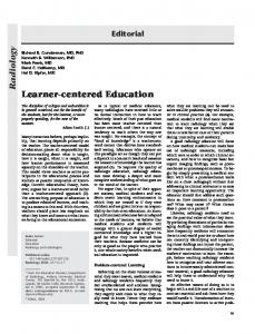
The purpose, focus, assumptions, and priorities of a software project are essential elements of an enterprise–wide vision statement. If any of these elements change during system acquisition and deployment, there is a significant risk that the models used to define the system will be obsolete. The first step in an architecture–centered development methodology is to establish a viable vision statement, with the assumption that it should not be changed once acquisition and deployment have begun. Any changes that occur in the vision must be reflected in the project models and subsequent analysis and design. The vision statement becomes a binding agreement between the software suppliers and the software consumers — users of the system. This vision statement must be succinct, ranging from a single slide to less than 10 pages of text. The vision statement establishes the context for all subsequent project activities, starting with R EQUIREMENTS ANALYSIS and ending with the CONTINUOUS M IGRATION of the system. BUSINESS CASE ANALYSIS The creation of a Business Case Analysis is a critical success factor for any system project. Without a clear understanding of the costs and benefits of the proposed system architecture, the decision–makers cannot be presented with complete information. The style of the business case as well as the contents of the analysis is usually an organization specific issue. R EQUIREMENTS A NALYSIS A project's requirements define the external behavior and appearance of the system without specifying its internal structure [Somm97], [Jack96]. External functional behavior, however, includes internal actions needed to ensure the desired non–functional requirements of the external behavior. The external appearance comprises the layout and navigation of the user interface screens, transaction processing activities as well as the behavior of the system in terms of its abilities. These abilities are usually defined as adjectives for the properties that system possesses. Reliability, Availability, Maintainability, Scalability, Performance, Testability, Efficiency, Reusability, Interoperability, and Changeability as well as other non–functional properties of the system architecture. An effective approach for capturing behavioral requirements is through Use Cases, which consist of top–level diagrams and extensive textual descriptions [Schn98], [Buhr96], [Lamr97]. The Use Case notation is deceptively simple but has one invaluable quality — it enforces abstraction. It is one of the most effective notations devised for expressing complex concepts and a powerful way to ensure the top– level requirements are represented with simplicity and clarity.
Copyright ©, January 2002
18
Record Contact Customer
Sales
Record Sale
Dispatch Shipment Dispatcher
Shipper
Figure 4 – Use Case for Order Taking and Fulfillment.
Each circle, or individual Use Case, is accompanied by a description of relevant requirements. It usually takes the form of a list of sequential actions described in domain–specific prose. Use Case definitions are developed jointly with domain experts and provide a domain model of the system for the purpose of defining architecture. Once system integration and deployment begins, Use Cases are extended with system–specific scenario diagrams that will be elaborated in workflow, procedural changes and system tests [Buhr96], [Jaco92], [Schn98]. The appearance, functionality, and navigation of the user interface are closely related to the Use Cases. Low fidelity prototyping — drawing the screens with paper and pencil — can be effective. In all cases, end– user domain experts must be involved in the screen–definition process. With the Use Cases and user interfaces defined, the context for architectural planning has been established. In addition to generating documentation (including paper–and–pencil sketches or output from CASE tools), the contributors acquire a better understanding of the desired system capabilities in the context of the end–user domain. Use Cases provide a visible means of capturing the external behavior of the system. The next step in the requirements analysis is to partition the nouns and noun phrases, verbs and verb phrases generated by the Use Cases. This activity can be done through Class–Responsibility– Collaboration (CRC) Cards provide this capability. This technique identifies and specifies the data and processes of the system in an informal manner [Bell98]. The CRC Card method is based on the theory of role–playing in which the participants have specific knowledge about their own roles and make requests of other participants to gain knowledge of their roles. Through this role–playing the nouns and verbs of the system are revealed.
Copyright ©, January 2002
19
4 + 1 and UML If the UML is to be used in the development of the system architecture described in 4 + 1, then an understanding of how the different components of the UML can be assigned specific roles [Tanu98]: 4+1 Architecture Component
UML Notation
Scenario
Use Cases
Logical Views
Class Diagrams State Transition Diagrams Collaboration Diagrams
Development View
Component Diagram
Physical View
Deployment Diagram
Process View
Class Diagram Deployment Diagram Figure 5 – UML to 4 + 1 Mapping
ARCHITECTURE P LANNING The process of “planning” the architecture involves more than listing the attributes of the system. It involves a deep understanding of how the elements of the architecture interact with each other as well as external elements. By their nature requirements are vague and ambiguous. Treating requirements elicitation like code development will surely lead to a disappointing result.
Requirements are inherently ambiguous, intuitive, and informal. Requirements are a right–brain activity. Software is logically unintuitive (i.e. hard to decipher) and meant to be interpreted unambiguously by a machine. Software is a left–brain activity. Architecture bridges the semantic gap between the requirements and software. Architecture's first role is to define the mapping between the Requirements and the Software. Architecture captures intuitive decisions in a more formal manner, making it useful to programmers and system integrators, and defines the internal structure of the system before it is turned into code so that current and future requirements can be satisfied. However, architecture also has another significant role: it defines the organization of the software project. Architecture planning is the missing link in many software projects, processes, and methods, often because no one is quite sure what architecture really is [Rech97], [Perr92], [Kruc95], [Bass98], [Shaw96]. One framework for defining software architecture is provided by the ISO standard for Open Distributed Processing (ODP) called the International Standard ISO/IEC 10746 (ITU [10] X.900), 1995. ODP is a way of thinking about complex systems that simplifies decision–making. It organizes the system architecture in terms of five standard viewpoints [ISO94a], [ISO94b], [ISO94c], [ISO94d]: n
Enterprise viewpoint – the purpose, scope, and policies of the business system as defined by the workflows and business rules.
Copyright ©, January 2002
20
n
Information viewpoint – the semantics of information and information processing.
n
Computational viewpoint – the functional decomposition of the system in modules, interfaces and the messages exchanged across the interfaces.
n
Engineering viewpoint – the infrastructure required to support the distributed environment.
n
Technology viewpoint – choice of technology for the implementation of the system.
Requirements Analysis
Functional Specification
Enterprise
Information
Design
Implementation
Computational
Engineering
Technology
Figure 6 – The RM–ODP Viewpoints and Software Engineering, from [ISO94a]
Each viewpoint defines the conformance to the architectural requirements. Without this conformance to requirements, the architecture is meaningless, because it will have no clear impact upon implementation. ODP facilitates this process by embodying a pervasive conformance approach. Simple conformance checklists are all that are needed to identify conformance points in the architecture. The ODP+4 methodology — based on the 4+1 Architecture [Kruc95] — generates an Open Distributed Processing architecture as well as formal and informal artifacts, including the Vision Statement, the Use Case–based requirements, the rationale and the conformance statements. Enterprise Viewpoint The enterprise viewpoint defines the business purpose and policies of the system in terms of high–level enterprise objects. These business– object models identify the essential constraints on the system, including the system objective and important policies. Policies for business objects are divided into three categories: n
Obligations – what must be performed by the system.
n
Permissions – what can be enforced by the system.
Copyright ©, January 2002
21
n
– what must not be performed by the system.
A typical Business Enterprise Architecture comprises a set of logical object diagrams (in UML notation), and prose descriptions of the diagram semantics [Larm97]. The language of the enterprise view is concerned with the performable actions that change policy, such as creating an obligation or revoking permission.
Customer
salesOrder
-name -address -phone
-value -fullFillment -made
sales Item -dispatched -note -price -ordered
product dispatch -date
dispatchItem
account -balance
-depletionRatio -stock -available
catalog accountItem
payment
sale
Figure 7 – UML notation for describing the enterprise–wide data objects for a sales company.
When preparing the enterprise viewpoint specification, policies are determined by the organization rather then imposed on the organization by technology implementation choices.
Information Viewpoint The information viewpoint identifies what the system must know, expressed as a model, emphasizing attributes that define the system state. Because ODP is an object–oriented approach, the models also
Copyright ©, January 2002
22
include essential information processes encapsulated with attributes, [11] thus following the conventional notion of an object. Architectural objects are not programming objects. The information objects do not denote objects that must be programmed. On the other hand, the architecture does not exclude this practice. Architecture objects represent positive and negative constraints on the system. n
Positive constraints identify things that the system's software must do.
n
Negative constraints are things that the system's software does not have to do.
Knowledge of these constraints aids the designer in eliminating much of the guesswork in translating requirements to system. Architects focus their modeling on the system aspects of greatest risk, complexity, and ambiguity, leaving the more straightforward details for the development step. The information model does not constitute an engineered design. In particular, engineering analysis, such as database normalization, is explicitly delegated to the development activities. Computational Viewpoint The computational viewpoint defines the top–level application program interfaces (API). These are fully engineered interfaces of the subsystem boundaries. During implementation, the system integration team will develop application modules that comply with these boundaries. Architectural control of these interfaces is essential to ensuring a stable system structure that supports change and manages complexity. The computational viewpoint specification defines the modules (objects, API’s, subsystems) within the ODP system, the activities with these modules, and the interactions that occur among them. Most modules in the computational specification describe the application functionality. These modules are linked through there interaction descriptions. The CORBA Interface Definition Language (IDL), an ISO standard notation for ODP computational architectures, becomes a fundamental notation for software architects at these boundaries. It has no programming language and operating system dependencies, and can be translated to most popular programming languages for both CORBA and Microsoft technology based (i.e. COM/DCOM) systems. Engineering Viewpoint The engineering viewpoint defines the infrastructure requirements independent of the selected technologies. It resolves some of the complex system decisions, including physical allocation, system scalability, and communication qualities of service (QoS), and fault tolerance. The benefit of using an ODP+4 like framework is it separates the various concerns (design forces) during the architecture process. The previous viewpoints of ODP+4 resolved other complex issues of less
Copyright ©, January 2002
23
concern to distributed systems architects, such as APIs, system policies, and information schemas. Conversely, these other viewpoints were able to resolve their respective design forces, independent of distribution concerns. Decisions must be made regarding system aspects such as object replication, multithreading, and system topology. It is during this activity that the physical architecture of the system is developed. Technology Viewpoint The technologies that will be used to implement the system are selected in this view. At this level of detail, all other viewpoints are fully independent of these technology decisions. Since the majority of the architecture design process is independent of the deployed hardware, commercial technology evolution can be readily accommodated. A systematic technology selection process includes initial identification of the conceptual mechanisms (such as persistence or communication). Specific requirements of the conceptual mechanism are gathered from the other viewpoints and concrete mechanisms such as DBMS, OODBMS, and flat files are identified. Then specific candidate mechanisms are selected from available products. Other project factors, such as product price, training needs, and maintenance risks, are considered at this point. It is important to restate the rationale behind these selections, just as it is important to record the rationales for all viewpoints as future justification of architectural constraints. Many projects wrongly consider this technology view as system architecture. By developing the technical viewpoints before the other ODP architectural views, the project is turned upside down. P R O T O T Y P I N G T H E S YSTEM Screen definitions from the System Requirements Analysis can be used to create an on–line mockup of the system to show to end users and managers. Dummy data and simple file I/O can provide a realistic simulation for the essential parts of the user interface. End users and architects then jointly review the mockups and run through the Use Cases to validate requirements. Often, new or modified requirements will emerge during this interchange. Print outs of these modified screens can be created and marked up for subsequent development activities. Any modifications to requirements are then incorporated into the other architectural activities. Through the mockup, management can see visible progress, a politically useful achievement for most projects, that reduces both political and requirements–oriented risk. With rapid prototyping technologies such as screen generation wizards, mockups of most systems can be rapidly constructed. Building Block Based Development There are two distinct approaches to acquiring and deploying software systems:
Copyright ©, January 2002
24
n
Product based – which solves specific problems using components of individual systems. These components can be integrated to form a complete system, but the resulting integration may or may not posses the attributes of good architecture.
n
Asset based – which solves problems in different contexts using components that are architected to provide services greater than the sum of their parts. Application
Application Application
Application Application
Generalize Certify
Select and Specialize
Software Capital Assets Enhance Software Assets "we need to have ... X ... that could do ... Y
Figure 8 – The process of reusing asset base software systems.
In Figure 8, the architects’ role is to of avoid the inclusion of the product based must have… requirements that corrupt the architecture. Building Blocks of the Prototype Building blocks are an architectural paradigm that provides the means to construct system along three dimensions [TOGAF00]: n
Structure – determine the system decomposition parts and the relationship between the parts.
n
Aspects – model the functional decomposition of the system.
n
Behavior – deals with processing that takes place within the system.
Copyright ©, January 2002
25
Structure should be considered the most important of the three, since it is through structure that the system complexity can be reduced. This is the primary motivation for the architecture–centric view management of structure. Without control of structure, the resulting system is simply a collection of parts. Gaining any synergy from the collection is now longer possible without a structural framework in which to place the components and their interacting interfaces. The building blocks of a manufacturing system are usually centered on the ERP system, since the Bill of Material is owned by this application. In order to avoid a detailed discussion of ERP and its relationship with other business applications, a set of generic building blocks can be [12] developed which can be used for all manufacturing applications. Short Lead Times
Configurability Layered Extendibility
System Architecture
Incremental System Isolated Interface
Reusability Generic Functions
Reuse Low Development Effort
Testability Self Contained Conceptual Integrity Incremental Development & Deployment
High Quality
Layered Software
Component Technology
Dimensional Design
Aspects
Managed Complexity Behavioral Modeling
Requirements
Principles
Figure 9 – Generic Building Blocks of the system architecture
M ANAGING THE P ROJECT As the final step in the pre–development process, the project management team plans and validates the deployment schedule to resolve resource issues including staffing, facilities, equipment, and commercial technology procurement [PMI96].
Copyright ©, January 2002
26
At this stage the schedule is defined for the parallel incremental, external, and internal activities performed during INCREMENTAL D EVELOPMENT. External increments support risk reduction with respect to requirements and management support. Internal increments support the efficient use of development resources — for example, back–end services used by multiple subsystems. Current best practices suggest performing several smaller internal increments that support larger scale external increments, the so – called V–W staging approach [Redm97], [Cock95], [Cock99], [Boeh88]. The architecture–centric process provides for the use of parallel increments. Since the system is partitioned into well–defined computational boundaries, integration teams can work independently and in parallel with other teams, each within their assigned boundaries. Integration planning includes increments spanning architectural boundaries. The plan should be detailed for early increments and include re-planning activities for later in the project, recognizing the reality that project planners do not know everything up front. At this stage, the team should prepare a risk mitigation plan that identifies technical backups. The integration team involved in mockup and architecture prototyping should continue to build experimental prototypes using the relatively higher–risk technologies well in advance of most developers. This run–ahead team is an essential element of risk mitigation [Sist94], [Redm97], [McCo97], [Karo89], [Hump89], [Doro96], [Boeh91]. The final activity in project management planning is the architectural review and startup decision. Up to this point, the enterprise sponsors have made relatively few commitments compared to the full–scale deployment costs (about 25% of system cost). Executive sponsors of the project must make a business decision about whether to proceed with the system. This executive commitment will quickly lead to many other commitments that are nearly impossible to reverse (such as technology lock–in, expenses, and vendor–generated publicity). At this point, the system architects are offering the best possible approach given the current business and technology context. P ROTOTYPING THE ARCHITECTURE The architecture prototype is a simulation of the system architecture. System API definitions are compiled and stub programs are written to simulate the executing system. This architecture prototype will be used to validate the computational and engineering architectures, including the flow of control and timing across distribution boundaries. Using technologies such as CORBA, a computational architecture specification can be automatically compiled into a set of programming header files with distributed stubs (on the calling side) and skeletons (on the service side). Processing can be simulated in the skeletons with dummy code. Simple client programs can be written to send invocations across computational boundaries using dummy data. A small number of essential, high–risk Use Cases can be simulated with alternative client programs. At this point, the prototype execution is used to validate conformance with engineering constraints. This is also the time to
Copyright ©, January 2002
27
propose and evaluate changes to the COMPUTATIONAL VIEW, ENGINEERING V IEW, or TECHNOLOGY VIEW architectures. I N C R E M E N T A L D E P L O Y M E N T O F T H E S YSTEM Deployment starts with several essential activities. The integrators must learn and internalize the architecture and requirements. An effective way to achieve this is with a multi–day kickoff meeting, which includes detailed tutorials from domain experts and architects. The results of all previous steps can be leveraged to bring the integrators up to speed. Lectures should be videotaped so that replacement staff can be similarly trained. Each increment involves a complete development process, including design, coding, and testing. Initially, the majority of the increments will be focused on individual subsystems. As the project progresses, an increasing number of increments will involve integrating multiple subsystems [Cock95], [Cock99]. For most of the software integration activity, the architecture is frozen, except at planned points where architectural upgrades can be inserted without disruption. Architectural stability enables parallel development. For example, at the conclusion of a major external increment, an upgrade might be inserted into the computational architecture before the next increment initiates. The next increment starts with a software upgrade that conforms to the changes. In practice the need for and frequency of such upgrades decreases as the project progresses. The architect's goal is to increase the stability and quality of the solution based on feedback from development experience. A typical project requires two architectural refactorings (upgrades) to get to a stable configuration that is suitable for deployment. T RANSITIONING THE S YSTEM TO P RODUCTION Deploying the system to a pilot group of end users is an integral part of the development process. Lessons learned during this initial deployment will be translated to new development iterations. Schedule slips are inevitable, but serious quality defects are intolerable. Improving quality by refactoring the integration (improving software structure) is an important investment in the system that should not be neglected. At this stage, architectural certification — where the architect confirms that the system implementation conforms to the specifications and properly implements the end users' requirement — becomes extremely important. In effect, the architect should be an impartial arbitrator between the interests of the end users and the developers of the system. If the end users identify new requirements that affect architectural assumptions, the architect can assess the request and work with both sides to plan feasible solutions. O P E R A T I N G A N D M A I N T A I N I N G T H E S YSTEM Operations and Maintenance (O&M) is the proving ground to verify if the integration was done right. The majority of system cost will be expended
Copyright ©, January 2002
28
here, and as much as, 70% of the O&M cost will be due to system extensions. The associated requirements and technology changes are the main drivers of continuing development. Typically, half of each integrator’s time will be spent trying to figure out how the system works. Architecture–centered development resolves much of this confusion with a clear, concise set of documentation, i.e., the system architecture itself. CONTINUOUS M IGRATION OF THE S YSTEM COMPONENTS System migration to a follow–on target architecture occurs near the end of the system life cycle. Two major processes for system migration are called Big Bang (or Cold Turkey) and Chicken Little [Ston92], [Brod95]. [13] A Big Bang is a complete, overnight replacement of the legacy system. In practice, Big Bang seldom succeeds; it is a common antipattern for system migration [Brow98]. The Chicken Little approach is more effective and ultimately more successful. It involves simultaneous, deployed operation of both target and legacy systems. n
The Cold Turkey approach in which the legacy systems are replaced in– kind with the new systems. There are many impediments to this approach: n
A better system must be promised – the current user base expects that the replacement system will perform significantly better, since the effort necessary to deploy the new system needs to be paid back many times over.
n
Business conditions never stand still – the new system must be capable of evolving with the changing business conditions. As time moves on, the requirements themselves change. Changes in the deployed system must be capable of keeping up.
n
Specifications rarely exist for the current system – by definition, the legacy system is poorly documented.
n
Undocumented dependencies frequently exist in the current system – over time, the legacy system has become customized to meet the previous tactical requirements.
n
Legacy systems are usually too big to be simply cut over from old to new – millions of database entities and hundreds of mainframe applications are tightly coupled to form the legacy system. This complexity becomes a serious burden simply to understand.
n
Management of large projects is difficult and risky – all the problems associated with managing large projects are present.
n
Lateness is rarely tolerated – since the legacy system is mission critical, any delays become exaggerated.
n
Large projects tend to become bloated with new and unjustified features – once the system is opened to migration, all sorts of new features will be required.
n
Homeostasis is prevalent.
n
Analysis paralysis sets in – with all the issues stated above, the analysis activities become bogged down in details.
Copyright ©, January 2002
[14]
29
n
The Chicken Little approach in which the system components are incrementally migrated in place until the desired long–term objectives have been reached. n
Controllable – since the scope of each incremental effort can be managed within the overall architecture of the system vision. The failure of one step in the process does not affect the proceeding deployments. In principle, the failure of one step would also not affect future steps. Once the failed step has been corrected, the project would proceed as planned.
n
Only one step fails – there is no Big Bang approach, with an all or nothing result
n
Incremental, over time – effort, budgets, human resources can be incrementally deployed.
n
Conservatively optimistic – success is always in hand with incremental benefits paving the way.
In the Chicken Little approach, gateways are integrated between the legacy and target systems. Forward gateways give legacy users access to data that is migrated to the target system. Reverse gateways let target –system users have transparent access to legacy data. Data and functionality migrate incrementally from the legacy to the target system. In effect, system migration is a continuous evolution. As time moves on, new users are added to the target system and taken off the legacy environment. In the end, it will become feasible to switch off the legacy system. By that time, it is likely that the target system will become the legacy in a new system migration. The target system transition overlaps the legacy system migration. In the Chicken Little approach, TRANSITION, OPERATIONS AND MAINTENANCE and C ONTINUOUS MIGRATION are part of a continuous process of re–deploying the system to meet the ever changing needs of the business.
———
Copyright ©, January 2002
30
APPLYING THE METHODO LOGY A Critical Success Factor in the architecture business is the clear and concise application of a methodology (any methodology) to the problem. The attributes clear and concise cannot be over emphasized. The UML notation is one means of conveying clear and concise architecture, but other “languages” can be used.
The methodology described in the pervious sections must be deployed against a live system in order to be of any value to the organization. This section applies the methodology in a checklist manner. The architect, the developers, and the deployment team can use these checklists to ask questions about the proposed (or existing) system. Every great movement must experience three stages: ridicule, discussion, and adoption – John Stuart Mill.
T HE R O L E O F T H E A R C H I T E C T The architect’s role in all of these processes is to maintain the integrity of the vision statement using the guidelines provided in this White Paper. This can be done by: n
Continually asking architecture questions in response to system requirements, requests for new features, alternative solutions, vendor’s offerings and the suggestions on how to improve the system – does this suggestion, product or feature request fit the architecture that has been defined? If not, does the requested item produce a change in the architecture? If so, does this item actually belong in the system?
n
Continually asking the developers, integrators, and product vendors to describe how their system meets the architectural principles stated in the requirements. These questions are intended to maintain the integrity of the system for future and unforeseen needs, not the immediate needs of the users. Without this integrity, the system will not be able to adapt to these needs.
n
Continually adapting to the needs of the users and the changing technology. The discipline of software architecture is continually changing. The knowledge of software architecture is expanding through research and practice. The architect must participant in this process as well.
ARCHITECTURE M ANAGEMENT The management of the system architecture is a continuous improvement process much in same way any quality program continually evaluates the design and production process in the search for improvement opportunities. n
Architectural evaluation – the architecture of the proposed system is continually compared with other architectural models to confirm its consistency.
n
Architectural management – the architecture is actively managed in the same way software development is managed.
Copyright ©, January 2002
31
n
System design processes – there are formal design processes for software architecture, just as there are formal processes for software development. These processes must be used if the architecture is to have an impact on the system integrity.
n
Non–Functional design process – the non–functional requirements must be provided in the detailed system design. The design process will include the metrics needed to verify the non–functional requirements are being meet in the architecture.
Architecture Evaluation The ODP framework provides a number of functions to manage the architecture of the system [Booc99]: n
Management – how are the various components of the system being defined, created, and managed? Are these components defined using some framework, in which their architectural structure can be validated?
n
Coordination – are the various components and their authors participating in a rigorous process? Can the architectural structure of the system be evaluated across the various components with any consistency? Is there a clear and concise model of each coordinating function in the system?
n
Transaction – are the various transactions in the system clearly defined? Are they visible? Are they recoverable? Do the transactions have permanence?
n
Repository – is the data in the system isolated from the processing components?
n
Type management – is there a mechanism for defining and maintaining the metadata for each data and process type?
n
Security – have the security attributes of the system been defined before the data and processing aspects?
Architecture Management The computational specifications of the system are intended to be distribution–independent. Failure to deal with this transparency is the primary cause of difficulty in the implementation of a physically distributed, heterogeneous system in a multi–organizational environment. Lack of transparency shifts the complexities from the applications domain to the supporting infrastructure domain. In the infrastructure domain, there are many more options available to deal with transparency issues. In the application domain, n
Access – hides the differences in data representation and procedure calling mec hanisms to enable internetworking between heterogeneous systems.
Copyright ©, January 2002
32
n
Location – makes the use of physical addresses, including the distinction between local and remote resource usage.
n
Relocation – hides the relocation of a service and its interface from other services and the interfaces bounded by it.
n
Migration – masks the relocation of a service from that service and the services that interact with it.
n
Persistence – masks the deactivation and reactivation of a service.
n
Failure – masks the failure and possible recovery of services, to enhance the fault tolerance of the system.
n
Transaction – hides the coordination required to satisfy the transactional properties of operations. Transactions have four critical properties: Atomicity, Consistency, Isolation, and Durability. These properties are referred to as ACID [Bern97]. Atomicity means that the transaction execute to completion or not at all. Consistency means that the transaction preserves the internal consistency of the database. Isolation means the transaction executes as if it were running alone, with no other transactions. Durability means the transaction’s results will not be lost in a failure.
System Design Process The construction of software is based on several fundamental principals. These are called enabling techniques [Busc96]. All the enabling techniques are independent of a specific software development method, programming language, hardware environment, and to a large extent the application domain. These enabling techniques have been known for years. Many were developed in the 1970’s in connection with publications on structured programming [Parn72], [Parn85]. Although the importance of these techniques has been recognized in the software development community for some time, it is now becoming clear of the strong link between system architecture and these enabling principles. Patterns for software architecture are explicitly built on these principles. n
Abstraction – is a fundamental principle used to cope with complexity. Abstraction can be defined as the essential characteristic of an object that distinguishes it from all other kinds of objects and thus provides crisply defined conceptual boundaries relative to the perspective of the viewer. [Booc94]. The word object can be replaced by component or module to achieve a broader definition.
n
Encapsulation – deals with grouping the elements of an abstraction that constitute its stricture and behavior, and with separating different abstractions from each other. Encapsulation provides explicit barriers between abstractions.
n
Information hiding – involves concealing the details of a component’s implementation from its clients, to better handle system complexities and to minimize coupling between components.
Copyright ©, January 2002
33
n
Modularization – is concerned with the meaningful decomposition of a system design and with its grouping into subsystems and components.
n
Separation – different or unrelated responsibilities should be separated from each other within the system. Collaborating components that contribute to the solution of a specific task should be separated from components that are involved in the computation of other tasks.
n
Coupling and Cohesion – are principles originally introduced as part of structured design. Coupling focuses on inter–module aspects. Cohesion emphasizes intra–module characteristics. Coupling is measure of strength of association established by the connection from one module to another. Strong coupling complicates a system architecture, since a module is harder to understand, change, or to correct if it is highly interrelated with other modules. Complexity can be reduced by architecting systems with weak coupling. Cohesion measures the degree of connectivity between the functions and elements of a single function. There are several forms of cohesion, the most des irable being functional cohesion. The worst is coincidental cohesion in which unrelated abstractions are thrown into the same module. Other forms of cohesion – logical, temporal, procedural, and informal cohesion are described in the computer science literature.
n
Sufficiency, completeness, and primitiveness – sufficiency means that a component should capture those characteristics of an abstraction that are necessary to permit a meaningful and efficient interaction with the component. Completeness means that a component should capture all relevant characteristics of it abstraction. Primitiveness means that all the operations a component can perform can be implemented easily. It should be the major goal of every architectural process to be sufficient and complete with respect to the solution to a given problem.
n
Separation of policy and implementation – a component of a system should deal with policy or implementation, but not both. A policy component deals with context–sensitive decisions, knowledge about the semantics and interpretation if information, the assembly of many disjoint computations into a result or the selection of parameter values. An implementation component deals with the execution of a fully– specified algorithm in which no context–sensitive decisions have to be made.
n
Separation of interface and implementation – any component in a properly architected system should consist of an interface and an implementation. The interface defines the functionality provided by the component and specifies how to use it. The implementation includes the actual processing for the functionality.
n
Single point references – any function within the system should be declared and defined only once. This avoids problems with inconsistency.
n
Divide and conquer strategies – is familiar to both system architects and political architects. By dividing the problem domain into smaller pieces, the effort necessary to provide a solution can be lessened.
Copyright ©, January 2002
34
Non –Functional Architecture The non–functional properties of a system have the greatest impact on its development, deployment, and maintenance. The overall abilities of the system are a direct result of the non–functional aspects of the architecture. n
Changeability – since systems usually have a long life span, they will age [Parn94]. This aging process creates new requirements for change. To reduce maintenance costs and the workload involved in changing a system’s behavior, it is important to prepare its architecture for modification and evolution.
n
Interoperability – the software system that result from a specific architecture do not exist independently from other system in the same environment. To support interoperability, system architecture must be designed to offer well–defined access to externally–visible functionality and data structures.
n
Efficiency – deals with the use of the resources available for the execution of the software, and how this impacts the behavior of the system.
n
Reliability – deals with the general ability of the software to maintain its functionality, in the face of application or system errors and in situations of unexpected or incorrect usage.
n
Testability – a system needs support from its architecture to ease the evaluation of its correctness.
A P P L Y I N G T HESE P R I N C I P L E S The following checklist can be used as a guideline for applying these principles. n
Develop a vision statement for the system. This vision statement must be acceptable not only to the management and executive team members, but to the end users as well. It is not uncommon to have a wonderfully crafted statement of the systems vision, that can be placed on the boardroom wall, only to have the shop floor user consider the vision out of touch with what actually happens in the real world. Developing the vision statement is not a simple task and should be given sufficient time and effort. This statement will form the foundation of the project and will be used to resolve conflicts in the direction of the development effort – why are we doing this is answered by the vision statement.
n
The business case process is common is most organizations. The constraints of the financial calculations will be defined ahead of time. The business case must consist of hard – bookable – savings. After these savings have been identified, soft savings can be considered.
n
The requirements analysis can take place in a variety of forms. The real goal here is to bring out the needs of the user, within the context of good system architecture. The users needs can be captured through
Copyright ©, January 2002
35
interviews, Use Cases, CRC Cards, or a nearly any requirements generation process. The primary goal of the architect is to prevent the requirements from corrupting the underlying system architecture. This tradeoff process requires skill and persistence. In many cases the user will articulate a requirement as a must have behavior of the system. The consequence of this requirement may damage the architectural structure of the system. The architect’s role is to incorporate the requirement without upsetting the architecture. This is done by iterating on both the requirements and the architecture until there is the proper fit. n
Using the IEC 10746 ODP structure, the architect defines the system from the five (5) viewpoints. The capturing of these viewpoints can be done through any appropriate tool. In the current OO paradigm, the UML notation is a powerful means of describing all five viewpoints. The complete UML language, in conjunction with CRC Cards, can describe the system logical and physical behavior.
n
The prototyping process provides a powerful means of trying out parts of the system design without the commitment to production. During the prototyping activity, the system architecture is being evaluated against the planned architecture. During this process, the architect must be vigilante to avoid compromising the structural, aspect, and behavioral integrity system without good cause. It is the natural inclination of the developers and end user to accept a work around at this point. This work around will become a permanent undesirable feature of the system if it is accept ed without the full understanding of the consequences.
n
The incremental deployment process should follow the Business Case analysis rollout strategy. The business case describes how the benefits will be booked over time and by which component of the organization. The system deployment must follow this benefit stream in order to accrue the savings.
n
The transition to production process is a continuation of the incremental deployment. The full training and operational support activities are now deployed.
n
The operation and maintenance of the system is then turned over to the production staff.
n
The continuous migration of the system is a process not usually considered part of system architecture. Without the architectural influences on this activity, the system will quickly decay into a legacy set of components.
AN EXAMPLE ARCHITECTURE There are numerous examples of layered architecture in the current literature. Presenting one here may appear redundant. However, we need to start some place and the EDM/PDM domain provides unique requirements not always found in general business systems. This example shown in Figure 10 is derived from [Hofm97] and adapted to the manufacturing domain.
Copyright ©, January 2002
36
In this example architecture the components are partitioned into functional layers: n
Workflow – is an application system that implements workflow metaphors for business processes. This component is usually a COTS product or at least a set of components that adheres to the Workflow Management Coalition specifications. The workflow component acts as a glue piece above all the application systems of the enterprise, integrating all the applications. If there is an atomic process to be performed, the work can be performed externally to the workflow system or as part of an application component embedded in the workflow process.
n
Interface Objects – are made up of two types: n
Dialog Interfaces – provide for the manipulation of kernel objects through graphical user interfaces. The interface objects are typically partitioned into presentation objects and dialog controls that manage the flow of control in the dialog.
n
Batch Interfaces – provide for manipulation of application kernel objects using batch processes. This batch processing is often neglected
n
Exception Handling – is a common service provided by the standard architecture. Exceptions ride up along the application domain until they reach the upper layer and can be handled by software or made visible to the users. In practice except handling consists of several exception classes and protocols plus components to map exceptions to meaningful messages for the users.
n
Application Kernel – is a set of components grouped by structural similarity, not by functional requirements.
n
n
Business transaction objects – a meaningful business process may require several steps or dialogs, which in turn interact with lower level business processes. Business transaction objects are used to control the sequencing of these actions.
n
Application kernel objects – provide the core set of functions needed for EDM or PDM. These functions are usually derived from the analysis of the business.
n
Pure functions – provide a core set of functions used by the application. These functions typically have a narrow interface, perform complex calculations or behavior (management change, format conversion, database processing).
Application System – consists of an interface and a set of application kernel objects that are manipulated through the interface.
Copyright ©, January 2002
37
Workflow System
External Formats
Panels and Controls
Batch Control
Dialog Control
Application Kernel Business Transaction Objects Pure Functions
Exception Handling
Interface Objects
Application Kernel Database Instance
Application System(s)
Figure 10 – A Standard Architecture
———
Copyright ©, January 2002
38
REFERENCES [Abow95]
“Formalizing Style to Understand Descriptions of Software Architecture,” G. Abowd, G. Allen and D. Garland, ACM Transactions on Software Engineering and Methods, 4(4), pp. 319–164, 1995.
[Adow93]
“Using Style to Understand Descriptions of Software Architecture,” G. Adowd, R. Allen and D. Garlan, ACM Software Engineering Notes, December, 1993, pp. 9–20.
[Adow97]
“Recommended Best Industrial Practice for Software Architecture Evaluation,” G. Abowd, L. Bass, P. Clements, R. Kazman, L. Northrop, and A. Zaremski, CMU/SEI–96–TR–025, Software Engineering Institute, Carnegie Mellon University, Pittsburgh, PA, January 1996.
[Alhi98]
UML in a Nutshell: A Desktop Quick Reference, S. S. Aihir, O’Reilly, 1998.
[Alle94]
“Formalizing Architectural Connection,” R. Allen and D. th Garlan in Proceedings of the 16 International Conference on Software Engineering, 1994.
[Alex79]
The Timeless Way of Building, C. Alexander, Oxford University Press, 1979.
[Alex77]
A Pattern Language: Towns, Buildings, Construction, C. Alexander, S. Ishikawa, and M. Silverstein, Oxford University Press, 1977.
[Aust98]
“How to Manage ERP Initiatives,” R. D. Austin and R. L. Nolan, Harvard Business School Working Paper.
[Bass98]
Software Architecture in Practice, L. Bass, P. Clements and R. Kazman, Addison Wesley, 1998.
[Bate95]
A System Engineering Capability Maturity Model, Version 1.1., R. Bate, D. Kuhn, C. Wells, & al, November 1995, CMU/SEI–95–MM–003, Software Engineering Institute, Carnegie Mellon University, Pittsburgh, PA 1995.
[Bell98]
The CRC Card Book , D. Bellin and S. Suchman Simone, Addison Wesley, 1998.
[Bern97]
The Principles of Transaction Processing, P. A. Bernstein and E. Newcomer, Morgan Kaufmann, 1997.
[Boeh91]
“Software Risk Management: Principals and Practice,” B. W. Boehm, IEEE Software, January 1991, pp. 32–41.
[Boeh88]
“A Spiral Model of Software Development and Enhancement,” B. Boehm, IEEE Computer, May 1988, pp. 61–72.
[Booc94]
Object Oriented Analysis and Design with Applications, 2ed, G. Booch, Benjamin / Cummings, 1994.
Copyright ©, January 2002
39
[Booc96]
Object Solutions, G. Booch, Addison Wesley, 1996.
[Booc99]
The Unified Modeling Language User Guide, G. Booch, J. Rumbaugh, and I. Jacobson, Addison Wesley, 1999.
[Booc99a]
“Conducting a Software Architecture Assessment,” G. Booch, Rational Software, www.rational.com/sitewide/support/whitepapers.
[Brod95]
Migrating Legacy Systems: Gateways, Interfaces & The Incremental Approach, M. L. Brodie and M. Stonebraker, Morgan Kaufmann Publishers, 1995.
[Brow98]
Anti–Patterns: Refactoring Software, Architectures, and Projects in Crisis, W. J. Brown, R. C. Malveau, H. W. McCormick III, and T. J. Mowbray, John Wiley and Sons, 1998.
[Bryn98]
“Beyond the Productivity Paradox,” E. Brynjolfsson and L. M. Hitt, Communications of the ACM, 41(8), pp. 49–55, August 1998.
[Bryn93]
“The Productivity Paradox of Information Technology,” E. Brynjolfsson, Communications of the ACM, 36(12), pp. 66-77, December 1993.
[Buch96]
A System of Patterns: Pattern Oriented Software Architecture, F. Buschmann, et. al, John Wiley & Sons, 1996.
[Burh96]
Use Case Maps for Object–Oriented Systems, R. J. A. Buhr and R. S. Casselman, Prentice–Hall, 1996.
[Chen76]
“The Entity Relationship Model – Towards a Unified View of Data,” P. Chen, ACM Transactions on Database Systems, 1(1), 1976, pp. 9–36.
[Clem96]
“Coming Attractions is Software Architecture,” P. C. Clements, CMU/SEI–96–TR–008, Software Engineering Institute, Carnegie Mellon University, Pittsburgh, PA, January, 1996.
[Cock99]
“Using ‘V–W’ Staging to Clarify Spiral Development,” A. Cockburn, Human and Technology, Inc. members.aol.com/acockburn/papers.
[Cock95]
“Unraveling Incremental Development,” A. Cockburn, Object Magazine, January 1995, pp. 49–51.
[Cook96]
Building Enterprise Information Architectures: Reengineering Information Systems, M. A. Cook, Prentice Hall, 1996.
[Davi90]
Software Requirements: Analysis & Specification, A. M. Davis, prentice Hall, 1990.
[DeMarc79]
Structured Analysis and System Specification, T. DeMarco, Prentice Hall, 1979.
Copyright ©, January 2002
40
[Dijk68]
“The Structure of the T.H.E. Multiprogramming System,” E. W. Dijkstra, Communications of the ACM, 26(1), January, 1968, pp. 49–52.
[DoD94]
Technical Architecture Framework for Information Management, United States Department of Defense, DISA Center for Architecture, 10701 Parkridge Blvd, Reston, VA, June 30, 1994.
[Doro96]
Continuous Risk Management Guidebook , A. J. Dorofee, et al, Software Engineering Institute, Carnegie Mellon University, 1996.
[Earl88]
Information Management: The Strategic Dimension, M. J. Earl, Oxford University Press, 1988.
[Foot97]
“Big Ball of Mud,” B. Foote and J. Yoder, University of Illinois at Urbana–Champaign, September 1997.
[Fowl97]
UML Distilled: Applying the Standard Object Modeling Language, M. Fowler, Addison Wesley, 1997.
[Garl93]
“An Introduction to Software Architecture,” D. Garlan and M. Shaw, Advances in Software Engineering and Knowledge Engineering, Volume 1, World Scientific, 1993.
[Garl95]
“Architectural Mismatch or Why It’s Hard to Build Systems Out of Existing Parts,” D. Garlan, R. Allen, and J. Ockerbloom, Proceedings of the Seventh International Conference on Software Engineering, April 1995.
[Gamm95]
Design Patterns: Elements of Reusable Object–Oriented Software, E. Gamma, R. Helm, R. Johnson and J. Vlissides, Addison Wesley, 1995.
[Ganti95]
The Transition of Legacy Systems to a Distributed Architecture, N. Ganti and W. Brayman, John Wiley and Sons, 1995.
[Gunn98]
“The Architect’s Role in Package Application Integration,” S. Gunnell, Sun World, August 1998.
[Fowl97]
Analysis Patterns: Reusable Object Models, M. Fowler, Addison–Wesley, 1997.
[Hofm97]
“Approaches to Software Architecture,” C. Hofmann, E. Horn, W. Keller, K. Renzel, and M. Schmidt, in Software Architecture and Design Patterns in Business Applications, edited by M. Broy, E. Denert, K. Renzel, and M. Schmidt, Technical University at Muhchen, TUM – I9746, November, 1997.
[Hopc79]
Introduction to Automata Theory, Languages and Computation, J. E. Hopcroft and J. E. Ullman, Addison Wesley, 1979.
Copyright ©, January 2002
41
[Hump89]
A Discipline of Software Engineering, W. A. Humphrey, Addison–Wesley, 1989.
[IEEE98]
“Recommended Practice for Architectural Description,” IEEE Standard P1471, 1998.
[ISO94a]
“Basic Reference Model of Open Distributed Processing – Part 1: Overview and Guide to Use,” ISO/IEC CD 10746– 1, July 1994.
[ISO94b]
“Basic Reference Model of Open Distributed Processing – Part 2: Descriptive Model,” ISO/IEC CD 10746–1, February 1994.
[ISO94c]
“Basic Reference Model of Open Distributed Processing – Part 3: Prescriptive Model,” ISO/IEC CD 10746–1, February 1994.
[ISO94d]
“Basic Reference Model of Open Distributed Processing – Part 4: Architectural Semantics,” ISO/IEC CD 10746–1, July 1994.
[ITU94]
International Telecommunications Union: Message Sequence Charts, ITU–T, Z.120, 1994.
[Jack96]
Software Requirements & Specifications, M. Jackson, Addison Wesley, 1996.
[Jaco92]
Object–Oriented Software Engineering: A Use Case Driven Approach, I. Jacobson, Addison Wesley, 1992.
[Kapc98]
“The World of the Technical Architect,” K. Kapczynski, Sun World, March 1998.
[Karo98]
Software Engineering Risk Management: Finding Your Path Through the Jungle, Version 1.0, D. W. Karolak, IEEE Computer Society, 1998.
[Kazm96]
“Classifying Architectural Elements,” R. Kazman, P. Clements, G. Abowd, and L. Bass, Proceedings of the ACM SIGSOFT Symposium on the Foundations of Software Engineering, 1996.
[Kruc95]
“The 4+1 View Model of Architecture,” P. Kruchten, IEEE Software, 12(6), pp. 42–50, 1995.
[Kuhn96]
Description of the System Engineering Capability Maturity Model Appraisal Method, Version 1.1., D. Kuhn, C. Wells, & al, March 1996, CMU/SEI–96–HB–004.
[Larm97]
Applying UML and Patterns: An Introduction to Object– Oriented Analysis and Design, C. Larman, Prentice Hall, 1997.
[Maho97]
High–Mix Low–Volume Manufacturing, T. M. Mahoney, Hewlett–Packard Professional Books, 1997.
[Mull97]
Instant UML, P.-A. Muller, WROX, 1997.
Copyright ©, January 2002
42
[McCo96]
Rapid Development: Taming Wild Software Schedules, S. McConnel, Microsoft Press, 1996.
[Mori98]
“Applications in Rapidly Changing Environments,” K. Mori, IEEE Computer, April 1998, Volume 31, Number Four, pp. 42–44.
[Parn72]
“On the Criteria to be Used in Decomposing Systems into Modules,” D. Parnas, Communications of the ACM, Vol. 15, pp. 1053–1058, December 1972.
[Parn85]
“The Modular Structure of Complex Systems,” D. Parnas, P. Clements, and D. Weiss, IEEE Transactions in Software Engineering, Vol. SE–11, No. 3, March 1985.
[Perr92]
“Foundations for the Study of Software Architecture,” D. E. Perry and A. L. Wolf, ACM Software Engineering Notes, October, 1993, pp. 40–52.
[PMI96]
A Guide to the Project Management Body of Knowledge, W. Duncan, Project Management Institute, 130 South State Road, Upper Darby, PA 19082, 1996.
[Pree94]
Design Patterns for Object–Oriented Development, W. Pree, Addison Wesley, 1994.
[Redm97]
Software Projects: Evolutionary versus Big Bang Delivery, F. Redmill, John Wiley & Sons, 1997.
[Rech97]
The Art of Systems Architecting, E. Rechtin and M. W. Maier, CRC Press, 1997.
[Rumb91]
Object–Oriented Modeling and Design, J. Rumbaugh, M. Blaka, W. Permerlaui, F. Eddy, and W. Lorenson, Prentice Hall, 1991.
[Sei98]
Continuous Risk Management, Software Engineering Institute, 1998.
[Sei00]
“Software Architecture Bibliographies,” Software Engineering Institute, http://www.sei.cmu.edu/architecture/bibliography.html
[Schr97]
“The Real Problem with Computers,” M. Schrage, Harvard Business Review, 75(5), November/December, 1997, pp. 178–183.
[Schn98]
Applying Use Cases: A Practical Guide, G. Schneider and J. P. Winters, Addison Wesley, 1998.
[Shaw96]
Software Architecture: Perspectives on an Emerging Discipline, M. Shaw, and D. Garlan, Prentice–Hall, 1996.
[Shaw96a]
“A Field Guide to Boxology: Preliminary Classification of Architectural Styles for Software Systems,” M. Shaw and nd P. Clements, Proceedings of the 2 International Software Architecture Workshop, October 1996.
Copyright ©, January 2002
43
[Sist94]
Software Risk Evaluation Method: Version 0.2, F. J. Sisti and S. Joseph, CMU/SEI–94–SRE, V0.2, Software Engineering Institute, January, 1994.
[Somm97]
Requirements Engineering A Good Practice Guide, I. Someerville and P. sawyer, John Wiley & Sons, 1997.
[Spew92]
Enterprise Architecture Planning, S. Spewak, John Wiley & Sons, 1992.
[D’Sou99]
Objects, Components, and Frameworks with UML: The Catalysis Approach, D. F. D’Souza and AS. C. Wills, Addison Wesley, 1999.
[Ston92]
“DARWIN: On the Incremental Migration of Legacy Information Systems,” M. Stonebraker and M. L. Brodie, TR–0222–10–92–165, University of California, Berkley.
[Sutc98]
“Supporting Scenario–Based Requirements Engineering,” A. G. Sutclifte, N. A. M. Maiden, S. Minocha, and D. Manuel, IEEE Transactions of Software Engineering, 24(2), December 1998.
[Tanu98]
“Software Architecture in the Business Software Domain: The Descartes Experience,” M. Tanuan, Proceedings of ISAW3, ACM 1998, pp. 145–148.
[TOGAF00]
http://www.opengroup.org/public/togaf/
[Upto97]
“A Path–based Approach to Information Technology in Manufacturing,” D. M. Upton and A. P. McAfee, Harvard Business School Working Paper.
[Voll97]
Manufacturing Planning & Control Systems, 4 Edition, T. E. Vollmann, W. L. Berry, and D. C. Whybark, McGraw Hill, 1997.
[Wirs90]
“Algebraic Specifications in Formal Methods and Semantics,” Handbook of Theoretical Computer Science, M. Wirsing, Elesiver, 1990, pp. 675–788.
[Witt94]
Software Architecture and Design Principals, Models, and Methods, B. I. Witt, F. T. Baker, and E. W. Merritt, Van Nostrand Reinholt, 1994.
[Zach87]
“A Framework for Information Systems Architecture,” J. Zackman, IBM Systems Journal, 26, Number 3, 1987.
th
Copyright ©, January 2002
44
END NOTES 1
Many of these architectural analogies are based on mapping the building architecture paradigm to the software architecture paradigm. If this were the actual case software systems would be built on rigid immovable foundations, with fixed frameworks and inflexible habitats and user requirements. In fact, software architecture is more analogous to urban planning. The macro level design of urban spaces is provided by the planner, with infrastructure (utilities, transportation corridors, and habitat topology) defined before any buildings are constructed. The actual dwelling spaces are built to broad standards and codes. The individual buildings are constructed to meet specific needs of their inhabitants. The urban planner visualizes the city–scape on which the individual dwellings will be constructed. The dwellings are reusable (remodeling) structures that are loosely coupled to the urban infrastructure. Using this analog, dwellings are the reusable components of the city–scape, similar to application components in the system architecture. In both analogies, the infrastructure forms the basis of the architectural guidelines. This includes, utilities, building codes, structural limitations, materials limitations, and local style [Alex79], [Alex77].
2
In many real life applications, there does not exist a solution to a problem that satisfies all the constraints. Such systems are called over constrained systems. An example might be the selection of matching cloths (shirt, shoes, and pants). There are red and white shirts, cordovan and sneaker shoes, and blue, denim, and gray pants. If the following matching constraints are used – Shirts and Pants: {(red, gray), (white, blue, (white, denim)}; Shoes and Pants: {(sneakers, denims), (cordovans, gray)}; Shirts and Shoes: {(white, cordovans)}, there is no solution.
3
Design Patterns and Pattern Languages are ways to describe best practices, good designs, and capture experience in a way that it is possible for others to reuse this experience. Fundamental to any science or engineering discipline is a common vocabulary for expressing its concepts, and a language for relating them together. The goal of patterns within any community is to create a body of literature to help the members of the community resolve recurring problems encountered during the development of the artifacts of the process. Patterns help create a shared language for communicating insight and experience about these problems and their solutions. Formally codifying these solutions and their relationships lets us successfully capture the body of knowledge which defines our understanding of good architectures that meet the needs of their users. Forming a common pattern language for conveying the structures and mechanisms of our architectures allows us to intelligibly reason about them. The primary focus is not so much on technology as it is on creating a culture to document and support sound engineering architecture and design.
4
Dr. John Rockhart from MIT's Sloan School of Management is the source of the concept of Critical Success Factors (CSF). The CSF’s for a business are associated with its industry, competitive strategy, internal and external environmental changes, managerial principles, and a CEO perspective.
Copyright ©, January 2002
45
5
The mainframe environment has been tagged with the monolithic label for some time. Now that mature client/server applications have been targeted for replacement, they too have been labeled monolithic. It is not the mainframe environment that creates the monolithic architecture, it is the application's architecture itself that results in a monolithic system being deployed. This behavior occurs when the data used by the application is trapped inside the code. Separating the data from the application is one of the primary goals of good software architecture. This separation however, must take into account the semantics of the data, that is the meaning of the data. This meaning is described through a meta–data dictionary which is maintained by the architect.
6
At this point, the separation between information systems and manufacturing systems is somewhat artificial. A Manufacturing Control System (MCS) can be defined as the software components that control the scheduling, material planning and production activities [Voll97]. The information processed by the MCS typically includes Bills–of–Material, Shop Floor Scheduling, Production Planning, Customer Configuration Instructions, Work Instructions, etc. A Manufacturing Information System (MIS) can be defined as the software components that author, distribute, inform, and interact with manufacturing personnel. The information conveyed by these systems is not directly involved in the scheduling and production of products, but rather forms the basis of these activities. The information processed by the MIS typically includes: Model and Drawing information, Planning Bills–of–Material, Product Support Information, Quality Assurance Information, etc.
7
The Channel, Verb, Noun, Semantics approach to defining interoperability is a high level concepts that can be used for nearly any architectural approach to system design.
8
The Use Case notation has become popular in object oriented design and development. The Use Case specifies the sequence of actions, including any variants, that a system can perform, interacting with actors of the system. [D’Sou99], [Jaco92], [Schn98]. Use Cases provide a functional description of the system but may not be appropriate for the non–functional requirements specification. When combined with sequence diagrams, Use Cases an describe the components of the system and the interactions between these components. These components include software, users, administrators, databases, and communication channels.
9
The Unified Modeling Language (UML) is a formal language used to capture the semantics (knowledge) about a subject and express this knowledge to others, including machines. The modeling aspects of UML focus on understanding a subject and capturing and communicating the knowledge about the subject. The unifying aspects of UML come about through the best practices of the industry, principles, techniques, methods, and tools. Although UML is object oriented it can be used in a variety of software and system settings using the definition of system architectures [Alhi98], [Mull97].
10
There are other frameworks pulmagated in the industry, ranging from commercially based paradigms to government standards: Software Engineering Institute, Manufacturing Systems Integration Division, National Institute of Standards and Technology, Department of Defense, and Quality Function Deployment. There is no universal standard for software architecture. The ODP is a generic set of guidelines appropriate for client/server environments as well as the emerging Internet and object oriented paradigms. The ODP defines five
Copyright ©, January 2002
46
viewpoint references (enterprise, information, computational, engineering, and technology). When used in conjunction with good system engineering practices and proven software development and system engineering guidelines, the ODP provides a clear and concise framework for the deployment of manufacturing centric systems. In addition to the ODP guideline several other architectures are in use today that require examination. The Zachman Framework [Zach87] is a traditional architectural approach that is not object oriented. It is a reference model with 30 architecture viewpoints based on two paradigms: Journalism (who, what, when, where, why, and how) and Construction (planner, owner, builder, designer, and subcontractor). Domain analysis which transforms project–specific requirements into general domain requirements for familiar systems. The 4+1 view model which is closely tied to UML and the Rational Unified Process. Many other architectural styles are defined in [Shaw96]. 11
This Object Oriented approach is motivated by several forces: ü
Vendors use Object Oriented (OO) methodologies to define the architecture of their products. In some cases the OO components are provided through a gateway creating a traditional system with OO wrappers. In other products the system is constructed using OO technologies. Other systems are hybrids of OO and traditional client/server and SQL database technologies.
ü
OO architecture pervades the Internet
ü
OO is a better means of analyzing systems requirements using UML, Use Cases, and CRC Cards.
12
Many ERP vendors provide toolkits for customizing the applications. In the past this approach was seen as a competitive advantage for both the vendor and the user. It is now understood that this approach is very expensive in terms of maintenance, upgrades, and continued operations and support. The tailoring aspects should be viewed from the user interface and federation interface paradigm, rather than tailoring the core functionality of the system. [Aust98], [Upto97]
13
The concept of Chicken Little and Big Bang or Cold Turkey originates from the two references. Stonebraker’s paper describes how GTE migrated 10,000 workstations using the business applications from a mainframe environment to a client/server environment [Ston92]. This work was done before the advent of CORBA ORB’s and the current trend of wrapping the applications into a federated system through the OO interface. The lessons learned in this work as well as the work at Boeing Aircraft Company in [Ganti95] supports the notion that a good architectural foundation is a mandatory requirement if there is going to be any hope that the outcome will be successful.
14
ho•me•sta•sis n.1. the tendency of a system to maintain internal stability owing to the coordinated response of its parts to any situation or stimulus tending to disturb its normal condition or function. 2. A state of psychological equilibrium obtained when tension or a drive has been reduced or eliminated.
Copyright ©, January 2002
47