University of Pennsylvania
ScholarlyCommons Departmental Papers (CIS)
Department of Computer & Information Science
10-2014
Architecture-Centric Software Development for Cyber-Physical Systems Oleg Sokolsky University of Pennsylvania,
[email protected]
Miroslav Pajic University of Pennsylvania,
[email protected]
Nicola Bezzo University of Pennsylvania,
[email protected]
Insup Lee University of Pennsylvania,
[email protected]
Follow this and additional works at: http://repository.upenn.edu/cis_papers Part of the Computer Engineering Commons, and the Computer Sciences Commons Recommended Citation Oleg Sokolsky, Miroslav Pajic, Nicola Bezzo, and Insup Lee, "Architecture-Centric Software Development for Cyber-Physical Systems", Proceedings of the First Workshop on Cyber-Physical System Architectures and Design Methodologies (CPSArch 2014) . October 2014.
First Workshop on Cyber-Physical System Architectures and Design Methodologies (CPSArch 2014) October 17, 2014, New Delhi, India. This paper is posted at ScholarlyCommons. http://repository.upenn.edu/cis_papers/778 For more information, please contact
[email protected].
Architecture-Centric Software Development for Cyber-Physical Systems Abstract
We discuss the problem of high-assurance development of cyber-physical systems. Specifically, we concentrate on the interaction between the development of the control system layer and platform-specific software engineering for system components. We argue that an architecture-centric approach allows us to streamline the development and increase the level of assurance for the resulting system. The case study of an unmanned ground vehicle illustrates the approach. Disciplines
Computer Engineering | Computer Sciences Comments
First Workshop on Cyber-Physical System Architectures and Design Methodologies (CPSArch 2014) October 17, 2014, New Delhi, India.
This conference paper is available at ScholarlyCommons: http://repository.upenn.edu/cis_papers/778
Architecture-Centric Software Development for Cyber-Physical Systems Oleg Sokolsky, Miroslav Pajic, Nicola Bezzo, and Insup Lee PRECISE Center University of Pennsylvania Philadelphia, PA, USA
{sokolsky, pajic, nicbezzo, lee}@seas.upenn.edu ABSTRACT We discuss the problem of high-assurance development of cyber-physical systems. Specifically, we concentrate on the interaction between the development of the control system layer and platform-specific software engineering for system components. We argue that an architecture-centric approach allows us to streamline the development and increase the level of assurance for the resulting system. The case study of an unmanned ground vehicle illustrates the approach.
1.
INTRODUCTION
Problem statement and motivation. Cyber-physical systems (CPS) are characterized by a tight interrelation between physical aspects of the system, computational algorithms that control and guide the system, and communication between independent entities within the system. This tight relationship makes design of cyber-physical systems a challenging problem (e.g., overviews of some modeling, analysis and integration challenges for CPS can be found in [16, 5]). Design decisions have to take all of these aspects into consideration, and system modeling and development tools and languages, such as Ptolemy II [4] and ESMoL [14], support modeling, simulation and development of such heterogenous systems. For example, Ptolemy II can be exploited for system design using an actor oriented approach. However, to the best of our knowledge, it only allows for the use of actors that are defined within Ptolemy. Similarly, the Embedded Systems Modeling Language (ESMoL) is a software architecture language [14] that allows for the integration of Simulink blocks and existing C code within Time-Triggered system architectures, while restricting component interactions that can be specified [16]. Existing CPS development frameworks usually assume the use of a single tool or tool-ecosystem. On the other hand, in CPS development process, different aspects of system development are typically handled by different groups within the project team and require different expertise. Historically, control engineers, embedded software developers, system in-
This research is supported in part by DARPA HACMS program under agreement FA8750-12-2-0247 and by GRL Program, NRF of Korea, Ministry of Science, ICT & Future Planning (2013K1A1A2A02078326). The views expressed are those of the authors and may not reflect the official policy or position of the sponsors. Permission is granted to the CPSArch 2014 organizers to distribute this paper to the workshop attendees by hosting it, with password protection, on the workshop website with the understanding that all copyright associated with this work is retained with the authors. First Workshop on Cyber-Physical System Architectures and Design Methodologies (CPSArch 2014) October 17, 2014, New Delhi, India .
tegrators, etc., worked separately. Existing development techniques, deeply entrenched in each of the communities, reflect this separation. However, CPS development demands closer collaboration between these groups and requires processes that support such closer collaboration. At the same time, tighter interaction between different aspects of the system requires changing the interfaces between these aspects. Control designers should be more aware of capabilities of the embedded platform, while designers of embedded networking should take chosen control strategies into account when planning communications within the system. This makes integration of the system more challenging, since a change in one aspect of the system renders other aspects inconsistent. Furthermore, it highlights the need to incorporate architectural modeling of the system as part of the design process, to ensure that each system component/functionality remain consistent with any architectural and system changes. The importance of the architectural system modeling has led to development of OMG SysML [9] widely used for systems engineering, and Architecture Analysis and Design Language (AADL) [6] for modeling of hardware and software architectures in embedded systems. In this paper, we consider a model-based approach to CPS development that aims to support techniques familiar to developers in each of the individual domains and at the same time facilitate closer interactions between development groups and reduce the challenge of integration of different aspects together. The motivation for this work comes from our experience with developing the control system for a relatively simple vehicular CPS. We initially applied a modelbased approach that relied on model analysis followed by code generation. However, we have encountered multiple hurdles that had to be overcome through significant manual effort at the integration stage. By incorporating architectural modeling into the development approach and using it to drive model analysis, we intend to alleviate these hurdles, ensure consistency between different model analysis and seamless integration of different system aspects. Challenges. The primary challenge in the CPS development is the heterogeneous nature of techniques used in the process. As a result, abstractions used in different phases of model-based CPS development are very different. Ideally, there should be a common abstraction to base the development on, or a set of compatible abstractions. However, such a common abstraction that works equally well for all aspects of development seems unlikely, at least in the short run. Furthermore, prevalence of certain development tools in some of the development phases, such as Simulink in the
domain of control systems, makes it difficult to find common ground. This is especially highlighted for tools (including Simulink) without clearly defined operational semantics In particular, Simulink becomes increasingly cumbersome to use once we move into the domain of low-level, platformspecific modeling and code implementation, partially due to its limitations in capturing issues such as concurrency, nondeterminism, etc. Even if it was possible to build all the necessary techniques into a single tool and base them on a common abstraction, we would still face resistance from developers familiar with prevalent tools in their domains. Because of this primary challenge, instead of searching for a common development approach, we advocate a framework that would allow us to use existing development technologies, ensuring their consistent application throughout the development process. The use of disparate technologies, however, brings forth the integration challenge, where components developed using different technologies and by different teams have to be put together in a consistent way. Integration challenges manifest themselves in multiple ways throughout the development process and arise through different kinds of integration. Here, we consider only a few of them. Horizontal integration is encountered whenever different aspects of the system functionality are developed independently and yield a collection of modules that operate logically concurrently and need to interact with each other. The challenges of horizontal integration are typically addressed by using interfaces that allow interaction, while abstracting away internal details of each module. Traditional interface definitions, however, do not take resource constraints such as computation time, communication bandwidth and latency, or power consumption into account. Resource-aware interfaces have been an active research area for a while. A different kind of integration challenge is vertical integration, where different aspects of behavior within a module need to be integrated together. Examples of vertical integration include extending functional code with fault-tolerance capabilities or adding platform-specific wrappers to platform-independent code generated by controller design tools. The vision of architecture-centric CPS development. We believe that the challenges of CPS development outlined above can be addressed by employing an approach built around an architectural model of the system and relying on virtual integration to build confidence in the system design before building it. Virtual integration [8] is a recent concept in model-based engineering that emphasizes the use of architectural models to ensure compatibility of independently developed modules within the architecture. The challenge in virtual integration is to find the right amount of detail in the model to make a trade-off between complexity and precision of analysis. We believe that such an approach would allow us to build an effective toolchain for CPS development, utilizing the strong aspects of existing legacy development tools to produce appropriate parts of the system implementation and seamlessly tie these parts together using virtual integration techniques.
2.
MOTIVATIONAL EXAMPLE
We are applying such an architecture-centric CPS development framework to the case study of control system development for the LandShark,1 a fully electric unmanned 1
See http://www.blackirobotics.com/.
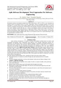
Figure 1: The LandShark vehicle while performing an attack resilient experiment. The user interface on the top right of the figure is used to control the robot, attack sensors, and visualize data.
ground vehicle (UGV), shown in Figure 1 performed as part of the DARPA HACMS program. The goal is to develop a resilient system for remotely controlled or autonomous navigation that can tolerate both cyber attacks via the teleoperation interface, as well as noninvasive attacks on system sensors. The effort involves multiple teams working on different aspects of the system. For our part, we have developed a cruise control application, consisting of a controller module and a resilient speed estimator (RSE) [13] that provides estimates to the controller module as well as to other modules within the system. The case study is affected by all of the challenges outlined in the introduction. At the same time, it has a moderate size and complexity, as well as relatively relaxed constraints. One of the challenges encountered in the case study is the need to contend with multiple tools that operate on different models and generate code for different aspects of the system that need to be integrated. The cruise control algorithm was implemented using Simulink, and platformindependent code for it was automatically generated using Simulink coder. The core of the RSE module solves an optimization problem using the solver generated by CVXGEN tool [10]. Input to the solver involves linear-algebraic manipulation of the sensor readings, which was implemented also using Simulink. The overall system is developed using ROS, a widely used component-based middleware for robotic system applications [15]. Each module was deployed as a ROS node that communicates with other nodes in the system. Thus, the platform-independent code of the controller and RSE modules had to be complemented with ROS interface code that performed periodic invocation of the modules and handled publish-subscribe interactions between nodes. The initial, rather naive development involved large amounts of manual effort in order to compose the auto-generated part of the code together and deploy it within ROS nodes. We had to rethink our development strategy and retarget it from manual post-implementation integration to automatic virtual integration. To enable this new strategy, we used a new development approach and designed several tools to support it, which we will describe in the remainder of the paper.
3.
DEVELOPMENT APPROACH
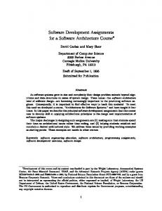
Figure 2 outlines the development process. The process comprises of the four distinct stages discussed below.
Modeling phase. Development begins with an architectural model of the system. Developers describe the architecture of the system, including physical components of the system, computing and communication infrastructure, as well as software modules that comprise the system. Attributes of components depend on the nature of a component. A physical component can specify its weight and dimensions, a processor can specify its speed and operating system, a software controller can specify the type of control algorithm, execution frequency or triggering events, and the entry point of the software function that implements the controller. An initial model is needed to proceed to other development phases. The model is not fixed and can evolve based on the outcomes of subsequence phases. In particular, outcomes of the analyses performed in the transformation phase described below help refine the model and enrich the set of attributes. Transformation and analysis phase. The architectural model is subject to a set of transformations. The purpose of each transformation is to extract an analysis model that targets a specific analysis technique and has the format expected by the tool performing this analysis. One of the key transformations for the control system design is the extraction of a mathematical representation of the control system. In the simplest case of such transformation, the software module in the architecture may specify that it implements a PID controller, which allows the transformation to yield the difference equations for a discrete-time PID controller. Parameters of the controller depend on a model of plant dynamics. We believe that a first-principles plant model can also be obtained from attributes of physical components in the architectural model. However, this aspect of model transformation has not been explored in our case study. The mathematical representation of the control system allows conventional control-theoretic analysis of the control system, which allows us to determine parameters of the control algorithm. We further transform this mathematical notation into computation-oriented notation that is familiar to control engineers. In our case study, described in Section 2, we use notation similar to the notation used in Simulink diagrams. The computation-oriented notation allows us to perform model-based validation of the controllers, as well as feasibility and performance analysis. In our case study, we performed extensive simulations on the Simulink models. Outcomes of the control-theoretic analysis and validation provide feedback to the architectural modeling phase, for example, that the computational infrastructure described in the architecture does not provide sufficient computational power to execute the control system with the desired performance. In that case, developers may refine the architecture, for example, to introduce more processors and map the RSE module and the controller module on different processors. Other transformations of the architectural model include a model for the analysis of schedulability, which would determine, for each software module, its worst-case response time and output jitter; and a network-calculus model of the system that can be used to determine end-to-end latency of data flows through the system and buffer size requirements. Values obtained through this analysis are recorded as additional attributes in the architectural model. Generation phase. Model transformations eventually yield notation that is amenable to code generation. The computationoriented representation for the control algorithm is used to generate platform-independent control code (“step func-
tion”) using, in our case study, the Simulink Coder tool. Similarly, platform-specific wrappers for control code is generated from the architectural model. Note that both platformindependent and platform-dependent code generation for different system modules is performed independently, exploiting the natural modularity delineated by the architectural model. In addition, the architectural model can include attributes that specify constraints on module operation and data flows through the system. These constraints can be used to generate monitors that check compliance with these constraints at run time. Integration phase. The approach supports virtual integration, that is, the ability to assess feasibility of the integrated system before components are built. Virtual integration is also facilitated by the architectural model. Attributes of the model are used for both vertical and horizontal integration. Vertical relations specify which functional code is running within the platform-specific wrapper in a module and allow us to verify that functional code is correctly interfaced with the platform. Horizontal integration is mostly concerned with sharing of resources between different nodes in the architecture, ensuring that there is sufficient capacity in the computing platform to run all the software modules, enough bandwidth in the communication platform to ensure timely communication between the modules, etc. In the case study, virtual integration was mostly concerned with checking that end-to-end delay from sensor readings to control actuation is within acceptable bounds. If the virtual integration, which happens in the model analysis phase, has been done right, actual integration of code modules can be expected to become a straightforward exercise. Our experience with the case study bears this hypothesis out. Framework instantiation. The approach described above is general and is not tied to specific modeling tools or deployment platforms. In order to apply the approach, the framework needs to be instantiated. Depending on the needs of a given application and expertise of the development team, we need to choose an architectural modeling language, a tool for computational modeling and simulation of control algorithms, and a deployment platform. Below, we describe a particular instantiation that we used in the LandShark case study. Other languages and tools can be used in instantiations just as easily.
4.
ARCHITECTURE MODELING: ROSLAB
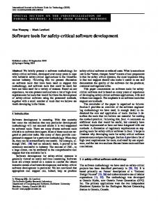
ROSLab [3] is a modular programming environment for robotic applications. It has been initially developed to support development based on ROS. ROSLab enables users to model an architecture of an application that consists of a set of computational nodes and communication channels between them. The interfaces of some commonly used nodes such as sensor and actuator nodes are pre-defined in ROSLab. Users can define a new node and its interface by selecting the channels to add to the interface of the node. While ROS was the initial target platform for ROSLab, the back-end code generation can easily be adapted for other platforms. Figure 3 shows an example of the implementation of ROSLab for the creation of a ROS node that receives a joystick input and sends throttle outputs to a ground vehicle like the LandShark in Figure 1. Each block dragged and dropped in the ROSLab workspace is characterized by specific interfaces that contain information such as frequency of operation, measurements variance, and jitter. This infor-
Figure 2: Outline of the development process mation is propagated to the mathematical control system representation block in Figure 2 to create an appropriate model for the system.
Figure 3: ROSLab environment: architecture of a remotely controlled ground vehicle Generation of hardware components. ROSLab was extended to provide a design environment for creating mechanical components of robots [12]. A component library of predesigned parametrized robotic building blocks are incorporated into ROSLab. Desired blocks can be dragged into a workspace, and parameters can be set by the user based on target specifications. Exposed interfaces on each robot component are represented by ports on the ROSLab block; these ports can be wired together to specify electromechanical connections. Assemblies of these blocks can be saved as components in the library to be used in future higher order designs. In this way, a full robot can be hierarchically composed from its constituent blocks. Once a robot has been designed, it can be compiled to generate manufacturing specifications. Our vision is to be able to extract a dynamical and kinematical model from the mechanical model developed though ROSLab. Physical parameters such as the dimension, weight, and moment of inertia, could be extracted from the designed system and then passed to the mathematical control system
representation block in Figure 2 to create a more accurate model of the plant. This is subject of on-going research. Generation of platform-dependent software. A ROSbased system usually consists of multiple communicating ROS nodes that can be deployed on the same processor or on different processors connected by a network. ROS nodes can be scheduled to run periodically or in response to incoming events, and communicate using a publish-subscribe mechanism. Nodes exchange messages organized into a set of topics. Platform-independent functional code, such as produced by control-code generation tools, needs to be connected to ROS services using glue code, to which we refer as a ROS wrapper. ROS provides an API to publish messages on selected topics, subscribe to topics of interest, schedule execution of the node, etc. Access to messages on the subscribed topics requires setting up callback functions that give access to topic buffers. Constructing a ROS wrapper manually is an error-prone process that requires detailed understanding of callback operation, relationship between callback invocation and node scheduling, data types of messages on the subscribed topics, and so on. ROSLab architectural models contain all the information necessary to configure a ROS wrapper. Connections of a node specify subscribed and published topics along with references to message types and buffer sizes for subscribed topics. Attributes of a node specify execution rates and the interface of the step function. We have implemented a wrapper generator using the Coq proof assistant [11]. In addition to eliminating the manual effort needed to construct the wrapper, wrapper generation allows us to automatically construct a proof that the wrapper is correctly generated with respect to the specification in the ROSLab model.
5.
FROM ARCHITECTURAL MODELING TO CONTROL SYSTEM DESIGN
Architectural modeling also facilitates control system design. The model captures the use of different control modules (blocks) and their interaction. Furthermore, information from the rest of the architectural model is utilized to populate some aspects of the system representation. For
example, a significant number of control laws are based on a discrete-time model of the controlled plant (e.g., model predictive control algorithms). Our vision is that architectural modeling of the physical part of the system (i.e., controlled plant) would allow for the automatic extraction of the plant’s model. In addition, schedulability and latency analyses provide implementation guarantees such as sampling times and jitter, which are used to obtain a discrete-time plant model. This enables initialization of the controller parameters, effectively resulting in a complete mathematical representation of the controller. The complete mathematical representation of the control system provides a basis for control theoretic analyses supported by the design process (e.g., robustness analysis from [13] in our case study), and in simple cases could be used for direct generation of the controller code. However, in general, we want to rely on established tools for simulation and code generation. We have designed the ACMG tool for automatic generation of Simulink control models, starting from the control system’s complete mathematical representation. The resulting Simulink model enables closedloop system simulation to evaluate closed-loop system performance. Violation of performance requirements would signal the designer to make changes in the architectural model to ensure satisfiable control performance. Finally, computational models used for simulation should provide a basis for code generation. In our development process, we utilize Simulink Coder to generate platform independent code (i.e., step function) from the (computational) Simulink model of the controller. Furthermore, the developed tool exploits the system’s mathematical representation to provide suitable annotation of the generated Simulink blocks and thus, the code generated by Simulink Coder. These annotations present invariants that the code has to satisfy, and are used as a basis to obtain correctness proofs for generated code.
5.1
Mathematical Representation of Systems
• A scope function S : C → {0, 1} specifying whether a unique variable should be associated with the link during code generation. Since our goal is to obtain code annotated with invariants that are predicates over some of the control system variables, it is necessary to ensure that automatic model generation followed by code generation would not remove the variables as part of code optimization. A functional representation fb of each block b captures behavior of the block, and can be specified as a mapping b b fb : Vin × Vlb → Vout × Vlb .
This allows us to describe behaviors of both standard static and dynamic control algorithms, and finite state machines, along with more complex hierarchical/hybrid controllers. Finally, realization parameter rb specifies how will the functional representation fb be implemented in the generated code. We consider the following three cases. 1) A block may correspond directly to an existing component (for example, a PID controller) in the library of some modeling tool. Currently, we support references to Simulink blocks. 2) When there is no pre-built component to implement the block, the ACMG tool we developed parses fb and creates a Simulink diagram that is used in simulation and code generation. 3) rb can also refer to existing code that will be linked in with the generated code. This supports interfacing with legacy code and other tools.
5.2
The attack-resilient controller used in our case study presents a composition of the RSE and a standard PID controller, whose input is speed estimation obtained by the RSE. The controller has three inputs, sensor measurement vector y, the last applied engine input ulast , and the desired speed r. The RSE block is represented by RSE Vin = {y, u}
To capture mathematical representation of a control system we use a representation similar to the one used in [1]. We describe a system as a tuple C = (V, B, E, S) with: • A finite set of variables V = Vin ∪ Vout ∪ Vl that can be partitioned into subsets containing input, output, and local variables.
RSE Vout = {x}
VlRSE = {y0 , ..., yN −1 , u0 , ..., uN −1 , Y, U}. In addition, functional description f RSE is specified as the following optimization problem:2 x = arg minn kY − Φxkl1 /l2 x∈R h i Φx = Cx|CAx| . . . |CAN −1 x
• A finite set of system blocks B. Each block b ∈ B has b b sets of input, output and local variables Vin , Vout , and b B b B Vl , and we define sets Vin = ∪b∈B Vin and Vout = b ∪b∈B Vout containing input and output variables of all blocks. In addition, each block b is associated with functional description fb and realization rb (we will describe block’s functional description and realization in the rest of the section). Finally, a system block can itself be a separately described system C 0 . B B • A relation E ⊆ Vout ∪ Vin × Vin ∪ Vout representing connections between system blocks – i.e., a connection 0 e = (vib , vjb ) ∈ E connects an output vib of block b 0 0 to an input vjb of block b0 , while e1 = (vi , vjb ) and b e2 = (vi , vj ) ∈ E respectively connect system input 0 vi ∈ Vin to input vjb of block b0 and output vib of block b to system output vj ∈ Vout .
Mathematical Representation of Attack-Resilient Cruise Controller
Y = [˜ y0 |˜ y1 | . . . |˜ yN −1 ] , ˜ k = yk − y
k−1 X
CAi Buk−1−i
(1) (2) (3) (4)
i=0
y0 = y, yk = yk−1 , k = 1, ..., N − 1
(5)
u0 = u, uk = uk−1 , k = 1, ..., N − 1.
(6)
It is worth noting here that matrices A, B and C, which effectively specify a linear model of the vehicle, are obtained in the modeling/transformation phase from the architectural system model that includes a model of the controlled physical process and some of hardware characteristics (e.g., sampling rates). 2
For a matrix Q ∈ Rp×N , kQkl1 /l2 denotes the sum of l2 norms of the matrix rows.
On the other hand, the PID controller’ inputs (desired input speed r and speed estimate x) and state xP ID are processed to produce engine control signal uout . Finally, we rely on Simulink for realization of the PID controller, and algebraic manipulations from Eq. (2)-(6) in the optimization problem, while to solve the optimization problem (1) we use code generated by CVXGEN.
5.3
Automatic Control Model Generation
We have developed the ACMG tool that transforms the aforementioned mathematical controller representation into a Simulink diagram, using the description of Simulink diagrams from [1]. The tool also automatically integrates existing (non-Matlab) code into Simulink, without the need for manual intervention. To achieve this, we exploit Simulink’s s-functions to include externally generated non-Matlab functions. By using s-function API, automatically generated models utilize Matlab Executable (MEX) files (obtained by precompiling existing code) for simulation, while directly incorporating the initial code into Simulink Coder-generated code. This allows for the use of a single Simulink diagram for both simulation and code generation. Finally, the ACMG uses the initial function representation of the system to annotate the obtained Simulink blocks, and thus generated code, with a set of invariants that specify relations between blocks’ inputs, outputs and local variables. In our case study, we are exploring the use of Coq-based Verified Software Toolchain (VST) [2] to show that generated code correctly implements specified functionalities, starting from linear operations specified by Eq. (2)-(6).
6.
DISCUSSION AND CONCLUSIONS
We have presented an architecture-centric model-based approach for the CPS development. The approach is motivated by a case study of a control system for an autonomous vehicle. While the case study used ROS as the deployment platform, modeling is not specific to ROS and generation tools can be easily adapted to other platforms. Control model transformations implemented by the ACMG tool are currently limited to Simulink. However, other computational representations can be supported. Some aspects of the described approach are subject of on-going research and implementation. In particular, ROSLab is being extended to support more transformations to analysis models, and specification of physical aspects of the system and extraction of plant models is on-going work. Generation of code invariants from the mathematical representation of a control system is an active research area [17, 7]. A full realization of architecture-centric development paradigm vision is a complex problem that can be achieved only by coordinated efforts of the CPS research community.
7.
REFERENCES
[1] R. Alur, A. Kanade, S. Ramesh, and K. C. Shashidhar. Symbolic analysis for improving simulation coverage of simulink/stateflow models. In Proceedings of the 8th ACM International Conference on Embedded Software, EMSOFT ’08, pages 89–98, 2008. [2] A. W. Appel. Verified software toolchain. In Programming Languages and Systems, pages 1–17. Springer, 2011.
[3] N. Bezzo, J. Park, A. King, P. Geghard, R. Ivanov, and I. Lee. Demo abstract: Roslab – a modular programming environment for robotic applications. In ACM/IEEE International Conference on Cyber-Physical Systems (ICCPS), page 214, 2014. [4] C. Brooks, E. Lee, X. Liu, S. Neuendorffer, Y. Zhao, and H. Z. (eds.). Ptolemy II - heterogeneous concurrent modeling and design in java. Technical report, University of California, Berkeley, 2005. [5] P. Derler, E. Lee, and A.-S. Vincentelli. Modeling cyber-physical systems. Proceedings of the IEEE, 100(1):13–28, 2012. [6] P. H. Feiler, D. P. Gluch, and J. J. Hudak. The architecture analysis & design language (aadl): An introduction. Technical report, DTIC Document, 2006. [7] E. Feron. From control systems to control software. Control Systems, IEEE, 30(6):50–71, 2010. [8] P. H.Feiler, J. Hansson, D. de Niz, and L. Wrage. System architecture virtual integration: An industrial case study. Technical Report CMU/SEI-2009-TR-017, CMU, 2009. [9] J. Holt and S. Perry. SysML for Systems Engineering. IET, 2008. [10] J. Mattingley and S. Boyd. CVXGEN: A code generator for embedded convex optimization. Optimization and Engineering, 13(1), 2012. [11] The Coq development team. The Coq proof assistant reference manual. LogiCal Project, 2004. Version 8.0. [12] A. Mehta, N. Bezzo, P. Gebhard, B. An, V. Kumar, I. Lee, and D. Rus. A Design Environment for the Rapid Specification and Fabrication of Printable Robots. In nternational Symposium on Experimental Robotics (ISER), Marrakech, Morocco, June 2014. [13] M. Pajic, J. Weimer, N. Bezzo, P. Tabuada, O. Sokolsky, I. Lee, and G. Pappas. Robustness of attack-resilient state estimators. In Cyber-Physical Systems (ICCPS), 2014 ACM/IEEE International Conference on, pages 163–174, 2014. [14] J. Porter, G. Karsai, P. V¨ olgyesi, H. Nine, P. Humke, G. Hemingway, R. Thibodeaux, and J. Sztipanovits. Towards model-based integration of tools and techniques for embedded control system design, verification, and implementation. In Models in Software Engineering, pages 20–34. Springer, 2009. [15] M. Quigley, B. Gerkey, K. Conley, J. Faust, T. Foote, J. Leibs, E. Berger, R. Wheeler, and A. Y. Ng. ROS: an open-source robot operating system. In Proceedings of the Open-Source Software workshop at the International Conference on Robotics and Automation (ICRA), 2009. [16] J. Sztipanovits, X. Koutsoukos, G. Karsai, N. Kottenstette, P. Antsaklis, V. Gupta, B. Goodwine, J. Baras, and S. Wang. Toward a science of cyber-physical system integration. Proceedings of the IEEE, 100(1):29–44, 2012. [17] T. Wang, R. Jobredeaux, H. Herencia, P.-L. Garoche, A. Dieumegard, E. Feron, and M. Pantel. From design to implementation: an automated, credible autocoding chain for control systems. Preprint arXiv:1307.2641, 2013.