71 Nanyang Drive, Singapore 638075. ABSTRACT. A Reconfigurable robot workcell is a collection of standardized components, such as actuators, rigid links,.
Architecture for Rapidly Reconfigurable Robot Workcell I-Ming Chen* Peter Chen+ Guilin Yang+ Weihai Chen+ In-Gyu Kang+ Song Huat Yeo* Guang Chen* *School of Mechanical and Production Engineering Nanyang Technological University Nanyang Ave, Singapore 639798 ABSTRACT A Reconfigurable robot workcell is a collection of standardized components, such as actuators, rigid links, tools, fixtures, sensors, and transport systems. These components can be rapidly assembled and configured to form a robotic workcell for a specific task. In this article, we describe the architecture of this type of reconfigurable workcells based on component technology. Both hardware and software aspects of the workcell are described. In addition, the control and simulation environment for the robot workcell, SEMORS, is introduced. 1. INTRODUCTION An automated manufacturing workcell usually consists of a collection of material processing and handling devices such as CNC machines, robots, part feeders, conveyors, and sensors. These devices are traditionally designed and commissioned with the intent that they will be operated with few significant changes for as long as the specific product is being manufactured. Certain flexibility has been given to those devices through programmable controllers. However, it is time-consuming and not cost effective to reconfigure them for other products. Such drawbacks reduce the attractiveness of automation systems for manufactures that are involved in highvariety, low-volume production. For manufacturers adopting the fixed automation systems, not being fast enough to market changes will place them at a disadvantage. The Nanyang Technological University and Gintic Institute of Manufacturing Technology are currently involved in a project to improve agility and flexibility in automation systems by developing a “rapidly reconfigurable” robot workcell. The key to the concept of reconfigurability in automation lies in component-based technology. Ultimately, workcells will be made of standard modular components, such as actuators, links, end-effectors, fixtures, and sensors. These components can be rapidly assembled and configured to form a robotic workcell according to specific task requirements. Based on this component-based concept, components can be reused for different workcell configurations. Also, the initial installment cost of such a system can be moderated by purchasing the minimum required parts. The
+
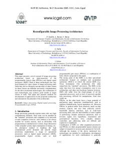
Automation Technology Division Gintic Institute of Manufacturing Technology 71 Nanyang Drive, Singapore 638075 maintenance and upgrading of the system becomes very easy by just replacing the malfunctioned or outdated components. Most important of all, converting one manufacturing line from one product to the other can be very fast and easy in order to keep up with the rapid changing marketplace. 2. HARDWARE COMPONENT 2.1 Modular Robots The major element in the workcell is the modular robot system. A modular robot can assume various robot geometry and DOFs for different task specifications. It consists of a pool of standard modules: actuators, rigid links, and end-effectors. Basically, the actuator modules are self-contained compact mechatronic drives with builtin motors, motor controllers, amplifiers, and communication bus. The actuators can be flexibly stacked together to form a multi-axes robot manipulator or can be used independently as individual motion control elements on the factory floor. They are connected through standard mechatronic interfaces, and communication networks. The link modules are rigid connectors with various geometrical shapes. From experience the geometry of the rigid links should be customizable based on the vendor specifications in order to fit the robot in a specific workspace. There exist several prototype modular robot systems in various research institutions [1,2,3,4]. For reliability purpose, we build the workcell based on one commercial source, the MoRSE modular robot system as shown in Figure 1. The main MoRSE components are the modular drives which contains internal PID control and Controller Area Network (CAN) bus communication system. Modular drives are daisy-chained in CAN-bus system and can communicate with a PC controller. The overall system is a distributed system with the PC controller monitoring and coordinating the activities of the local module controllers. The link units are rigid connectors that can be customized by the end-user. The connection between the link and actuator modules is through bolt screws that can be easily disconnected. The setup of a workcell with several modular robots is rendered as a computer simulation shown in Figure 2. We will show that the modular robot can be configured
as serial manipulators to perform parts assembly tasks and also as high-stiffness parallel manipulators to perform light machining tasks.
SERIAL
PARALLEL
Figure 1 Modular robot configurations
§ Device Controllers A device controller is essentially an interface between the device and the workcell supervisor. Since devices of different types from different vendors have their particular characteristics of operation, a device controller’s function is to hide such particularity from the workcell supervisor to lessen the analytical and computational burden of the supervisor, thus improving the “reconfigurability” of the workcell. Operationally, a device controller performs the following three types of tasks: (i) reporting device status, (ii) processing instructions from the workcell supervisor, and (iii) controling the device to execute the instruction. Workcell Supervisor
Data Server
Graphical Workstation
Supervisory Control and Monitoring Network PLC or Industrial PC controller Other Devices e..g. Vision Industrial PC
Figure 2 Workcell layout Modular Robot
2.2 Workcell devices The entire robot workcell consists of modular robot systems, material handling systems, sensors, device controllers and other peripheral devices. The hardware environment for both simulation and actual workcell implementation is illustrated in Figure 3. This is a PCbased system consisting of a workcell supervisor, a data server, a graphical workstation, and a group of workcell devices along with the modular robot that are controlled by their respective device controllers (e.g., the industrial PC). We also assume that the devices in the workcell other than the robot can be reconfigured. Therefore, the workcell components are connected to a workcell-wide communication network. § Supervisory Control Network A digital network facilitates communication among the workcell components. The choice of network implementation will ultimately depend on the bandwidth requirement, the connectivity of the network with the device controllers, and the reliability of the networking protocol. For demonstration purpose, we use 10Mb Ethernet protocol. § Workcell Supervisor During workcell operation, the supervisor receives reports from the device controllers regarding the status of the devices, and then, based on the status reports, issues instructions to the device controllers. The device controllers, upon receiving the instructions, activate the device to execution the instructions.
Conveyor
Sensors
Barcode Reader
Figure 3 Workcell hardware § Data Server The data server stores (i) system data (such as the kinematics and dynamics models of a robot) generated during off-line workcell programming, and (ii) run-time data relevant to the operation of the workcell. It receives data from two sources: the workcell supervisor and the device controllers. The data from the supervisor mainly concerns the coordination of the workcell, while the data from the device controllers reflects the real-time status of the devices. The data server also maintains real-time communication with the graphical workstation. It provides the graphical workstation the necessary data for visual display of the workcell activities. § Graphical Workstation The workstation executes a simulation program to display the real-time status of the workcell. It obtains the model data of the workcell devices from the data server, and the data concerning the real-time status of the devices from the device controllers. It is expected that the simulation program being executed on the graphical workstation will also support a user interface. This interface will allow a user to view in real-time the operation of the workcell from different perspectives and at different levels of details.
3. SOFTWARE COMPONENTS The software environment will support both on-line and off-line operations. On-line operation refers to workcell activities (such as sensing, actuating, and graphical display of workcell status, etc.) that occur during the execution of a task (such as polishing a part), while offline operations refer to activities associated with preparation for on-line operations or for processing of information after a task execution. To ensure the component-based concept to be applicable workcell-wide, the architecture of the workcell software adopts the reusable component software concept. There are several commercially available component software formats, such as COM and CORBA. In this project, we follow the standard of COM closely. Figure 4 depicts the software components. Each block represents a program or a set of data. Shaded blocks are programs associated with off-line operations, non-shaded blocks represent online operations, and 3D blocks represent system data. The arrows indicate directions of information flow. Note that in actual implementation, some of the information may flow from one component to another through the data server. Also some information needed by various processes may be obtained from the data server; the specific routes of such information flow are not indicated in the overall representation depicted in Figure 4. Workcell Tasks
Workcell Layout Optimization Algorithm
Workcell Layout
Robot Configuration Optimization Algorithm
Robot Kinematics Model
Task Planner
Task Scheduler
Robot Dynamics Model
Workcell Supervisor
Device Controller
Graphical Display
robot kinematic model residing in the modular robot controller. Hence, a data structure will be defined for automatic model generation. Subsequently, a general inverse kinematics algorithm for modular robots is implemented based on numerical Newton-Raphson method [5]. § Robot Dynamics Model A dynamics model of a robot specifies the dynamical behavior of the robot. A forward dynamics model specifies the motion of the robot under actuation, while an inverse dynamics model specifies the required actuation so that the robot can achieve certain motion trajectory. The parameters of a dynamics model are usually represented symbolically. The specific values of these parameters can be determined (analytically or experimentally) to “characterize” the model. Similar to the case of robot kinematic models, we also developed automatic model generation for robot dynamics based on Newton-Euler recursive algorithms. [6] § Kinematic Calibration Algorithm The process of determining and refining the values for the kinematic parameters of the robot model is referred to as kinematic calibration. For modular robots, frequent module reconfiguration will create mechanical errors in the nominal kinematic model. Thus, kinematic kinematic calibration is necessary. The robot calibration follows the local POE model. The differential transformation theory and linear superposition principles are utilized in the calibration model. An iterative least-squares algorithm is used to identify the robot actual kinematics parameters. Because of the use of local coordinates, this algorithm is easy to set up and can deal with robots of different joint types and arbitrary DOFs. Furthermore, the Local POE model varies smoothly with the change of joint axes, which makes the model singularity free. [7]. 3.2 Workcell Level
Graphical Workcell Model
Calibration Algorithm
Database
Figure 4: Software component 3.1 Modular Robot Level § Robot Kinematics Model A kinematics model of a robot specifies the geometrical relationships among the links and joint of the robot. Here, the robot kinematic algorithm is formulated based on the Local Product-of-Exponentials (POE) formula [4]. It is a local coordinate representation of the joint axes is established for a general robot configuration. The forward kinematics can be expressed as a product of matrix exponentials. For the modular robot system, no specific robot geometry and configuration will be given in advance. Unlike conventional robot system, there is no
§ Workcell Task Planner A workcell task is one that specifies a complete operation of the workcell. For instance, a statement such as Polish Part A is a workcell task. Workcell tasks (which is input to the task planner) are usually generated from some factory-level production planner. For the current implementation, a user could generate the workcell tasks. The task planner takes a set of workcell tasks as its input, and generates a set of device tasks to be performed by the workcell.. A device task is one that can be interpreted and executed by a device controller. For instance, an instruction for the robot such as Execute Command Sequence #1 is a device task, where the sequence labeled #1 may contain a set of specific robot commands. A workcell task must be decomposed into a set of device tasks for execution. For example, assume that the part is being moved around by a PLC-controlled conveyor continuously, and can be stopped for a robot to perform
the polishing task. To execute the workcell task Polish Part A, the device tasks may be specified as follows: From Workcell Supervisor to
Device Task Instruction
Description
PLC
Execute Program #2
§ Stop pallet if part presence is detected by sensor. § Report to workcell supervisor that part is ready.
Robot Controller
Execute Task #1
§ Approach workpiece. § Polish workpiece. § Retreat. § Report to workcell supervisor that polishing is done.
PLC
Execute Sequence #3
§ Release pallet to conveyor. § Report to workcell supervisor that part has been released.
§ Robot Configuration Optimization Algorithm The task planner generates a set of device tasks associated with a given workcell task. A set of device tasks for a robot may consist of robot command such as Move A 0.2, which can be interpreted to mean moving the robot end-effector from the current location to a new location A at 20% of the maximum rated speed. Given a set of such robot commands, the robot configuration optimization algorithm will generate an “optimal” robot configuration, which specifies the DOF, the type of joints, etc. It is based on such a configuration that a modular robot is assembled to perform the tasks. Several task-optimal configuration algorithms have been proposed for modular robots. Basically finding the most suitable task-oriented robot configuration is a design optimization problem. Genetic algorithms and other artificial intelligence techniques are employed for solutions. [8,9] § Workcell Layout Optimization Algorithm For a given workcell task, the workcell layout optimization algorithm determines the necessary workcell devices for performing the task. It also determines a suitable arrangement of the workcell devices such that the device tasks (generated by the task planner) can be effectively carried out. The output of this algorithm is a set of data (as indicated by the 3D block Workcell Layout) specifying the devices required, and their respective locations of deployment. § Task Scheduler The task scheduler decides the sequence by which a set of workcell tasks is to be executed. For tasks that have no deadline, the tasks can be executed in any order. For tasks that have specific deadline, schedulability of the tasks should be first examined. If the tasks are determined to be schedulable, then scheduling algorithms, such as the Earliest-Deadline-First algorithm, can be used to yield an execution sequence. For tasks that are both periodic and have hard deadlines, scheduling will require more complicated algorithm [10].
A full version of the task scheduler must be able to deal with these three cases. § Workcell Supervisor The workcell supervisor is a program that coordinates the activities of the various devices in to execute a set of device tasks. It issues instructions to the workcell devices based the current workcell status, and ensure that the instructions are executed properly. Error detection and recovery algorithms can be incorporated into the workcell supervisor in order to improve its robustness. § Device Controller The instructions from the supervisor to a device controller are at the task level. They indicate what needs to be done by the device, but do not contain specific information as to how the task is to be carried out by the device. For instance, an instruction to the robot might be specified as: Execute Assembly Task #1, (or it could be simply a number, say, 1) which instructs the robot to execute a pre-programmed assembly task labeled as Task #1. The device controller of the robot (i.e., the industrial PC in this case) must process the instruction locally, by retrieving (from local memory or from the workcell database) the robot commands associated with this instruction and send these commands to the robot in order to execute the task properly. For a device with rudimentary functions, such as a conveyor, local processing of the instruction by the device controller (e.g., the PLC) could be relatively simple. § Workcell Database The database stores data generated from both off-line and on-line operations. These include the workcell layout, the robot kinematics and dynamics models, the graphical workcell model, and data collected by the devicecontrollers and the workcell supervisor during workcell simulation and actual operation. § Graphical Display The graphical display is program that manages the 3D representation of the workcell activities. It also serves as a simulation tool for visual verification of workcell operations. 4. CONTROL AND SIMULATION 4.1 Control Two levels of control exist in the workcell. One is supervision of the workcell activities; the other is realtime control of individual workcell devices. The workcell supervisor performs supervisory control of the workcell. The supervisor coordinates the activities of the workcell by collecting reports from the device controller regarding the status of the workcell, and then, based on these reports, dispatching device task instructions to the device controllers. The device controllers do the control of the individual devices. Each device controller is equipped
with its own real-time control system to ensure that the assigned tasks are completed properly. 4.2 Simulation Simulation is conducted in a power-off setting, where all workcell components are operational except the actual devices (which are turned off). The simulated activities of the workcell are displayed graphically on the graphical workstation. During on-line operation, the workstation displays the workcell status in synchronization with the physical events taking place in the workcell. 4.3 SEMORS The robot control and simulation environment (a.k.a. SEMORS) is a software application currently under development to manage the off-line programming and the real-time operation of the robot. It enables a user to § Construct the kinematics and dynamics models of a robot based on a set of predefined modules, § Graphically generate a desired trajectory for the robot endeffector, § Compose a robot task sequence § Select a control law for the robot to execute the desired trajectory and task, § Specify how output data are to be stored, § Run a simulation, and § Execute the task.
displayed on the either the workcell supervisor or the data server. 6. SUMMARY We have presented a new type of reconfigurable robotic workcell for rapid deployment and agile manufacturing. The key idea is to design the entire workcell based on the component technology, not only the hardware parts but also the software and control parts. Components are connected through standard hardware and software interfaces. The major element in the workcell is the modular reconfigurable robot system that can be configured into any geometry, any DOFs, including both serial and parallel types of configurations. Currently we are in the first stage of the implementation: building the simulation, control, and hardware environment for a single reconfigurable robot workcell, i.e., an SEMORSenabled modular robot. Ultimately, we will demonstrate a set of fully connected reconfigurable robotworkcells to perform various applications including light machining tasks (for example, polishing, grinding, and deburring), and assembly tasks (for example, odd parts insertion). Acknoledgement: This project is supported by Gintic Institute of Manufacturing Technology, Singapore, Under Upstream Project U97A006.
The general layout of SEMORS is illustrated in Figure 5. It consists of a set of menus and three display areas. Display Area I shows the tools and resources (such as the set of modules available for assembling a new robot) required during off-line programming. Display Area II shows the graphical results of the use programming, e.g., the robot as it is being assembled. The User Input Area is for the prompting and accepting user input. SEMORS is intended to be a uniform interface for all modular robots. It will be used both for simulation and for on-line execution of a task, regardless of whether the robot is executing (or is simulated to be executing) the task as a stand-alone application, or as part of a workcell process.
Figure 5 GUI of SEMORS
5. DATA MANAGEMENT AND PRESENTATION
7. REFERENCES
The main resource for data management and presentation is the data server. All data pertaining to the operation of the workcell is stored on this server. The device controllers and the workcell supervisor may store some information locally to facilitate timely operations.
[1] R. Cohen, M. Lipton, M. Dai, B. Benhabib, Conceptual Design of a Modular Robot. ASME J. Mechanical Design, Vol. 114, pp117-125, 1992.
Workcell data can be displayed on the workcell supervisor, the data server, and the graphical workstation. Each may display a set of data associated with its own functionality. Unless an industrial PC is used as the device controller for the conveyor and sensors, data associated with these devices can be
[2] T. Fukuda, S. Nakagawa, Dynamically Reconfigurable Robot System. Preceedings of IEEE Conf. Robotics & Automation, pp1581-1586, 1988. [3] C.J.J. Paredis, H.B. Brown, R.W. Casciola, J.E. Moody, P.K. Khosla, A Rapidly Deployable Manipulator System. International Workshop on Some Critical Issues in Robotics, Singapore 1995. [4] I.M. Chen, G. Yang, Configuration Independent Kinematics for Modular Robots. Proceedings of IEEE Conf. Robotics & Automation, pp1845-1849, 1995. [5] I.M. Chen, G. Yang, Inverse Kinematics for Modular Reconfigurable Robots. Proceedings of IEEE Conf. Robotics & Automation, 1998.
[6] I.M. Chen, G. Yang, Automatic Model Generation for Modular Reconfigurable Robot Dynamics, ASME J. Dynamic Systems, Measurement, Contrl, to appear. [7] I.M. Chen, G. Yang, Kinematic Calibration of Modular Reconfigurable Robots Using Product-of-Exponentials Formula. J. Robotic Systems, Vol. 14, No. 11, pp807-821, 1997. [8] I.M. Chen, J. Burdick, Determining Task Optimal Modular Robot Assembly Configurations, Proceedings of IEEE Conf. Robotics & Automation, pp132-137, 1995. [9] G. Yang, I.M. Chen, Reduced DOF Modular Robot Configurations, ICARCV, Singapore, 1998. [10] C.Y. Chen, I.M. Chen, Scheduling of Reconfigurable Workcells for Hard-real-time Manufacturing Operation. ICARCV, 1998.